10. Open Source Hardware - From Fibers to Fabric
Result: the BioPower2022
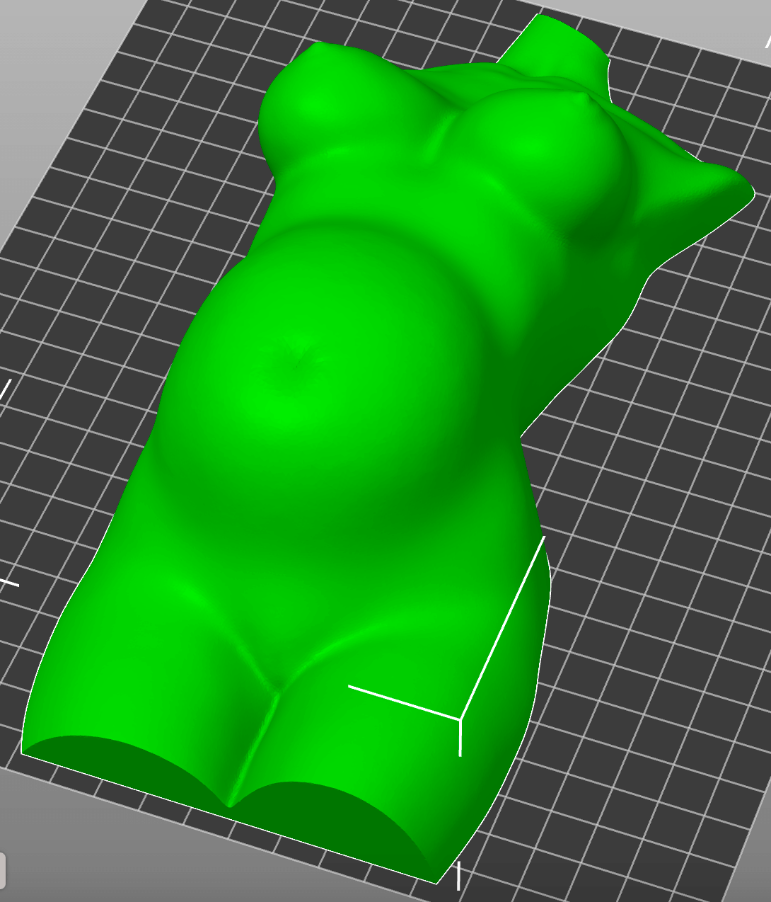
Our wish - we wanted to print this 3D lady with biomaterial:
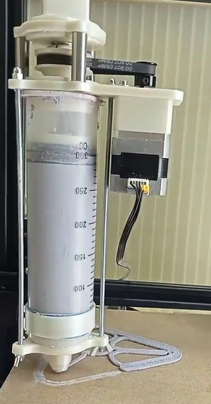
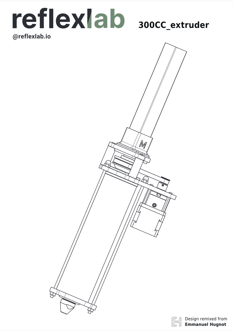
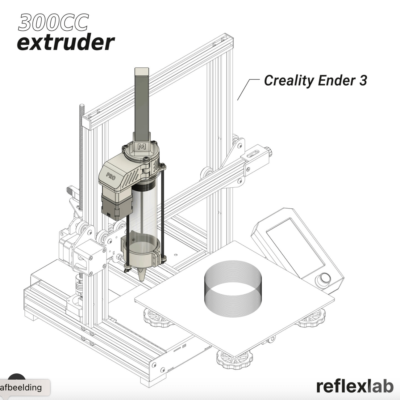
Therefore we built an extension for the Ender 3D printer, to convert it in a biomaterial printer. We had a building plan for this from the organisation reflexlab. For the assembly we needed a mixture of 3D printed components and sourced hardware. This is how the prototype of reflexlab is printing:
Printing with the 300CC Extruder from reflexlab
It wasn't supposed to be too difficult, but when you miss the proper hardware, it becomes a journey of troubleshooting and workarounds.
Inspiration and brainstorm
After seeing the many interesting machines during the lecture, we were of course inspired and a little intimidated. On Wednesday morning we started the day with an inventory of what we wanted. In the end we had the following list on the whiteboard:
- Pigment spray drier
- Biogun for biomaterials
- Bio-extruder
- Spinning machine
- Loom machine
The last two options didn't really fit our preliminary thoughts around our final projects. The biogun had been made a few years ago in Amsterdam. We hesitated between the pigment spray drier and a bio-extruder.
The Imperial graduate Nicole Stjernswärd has invented Kaiku, a system that turns plants into powdered paint pigments using vaporisation technology.
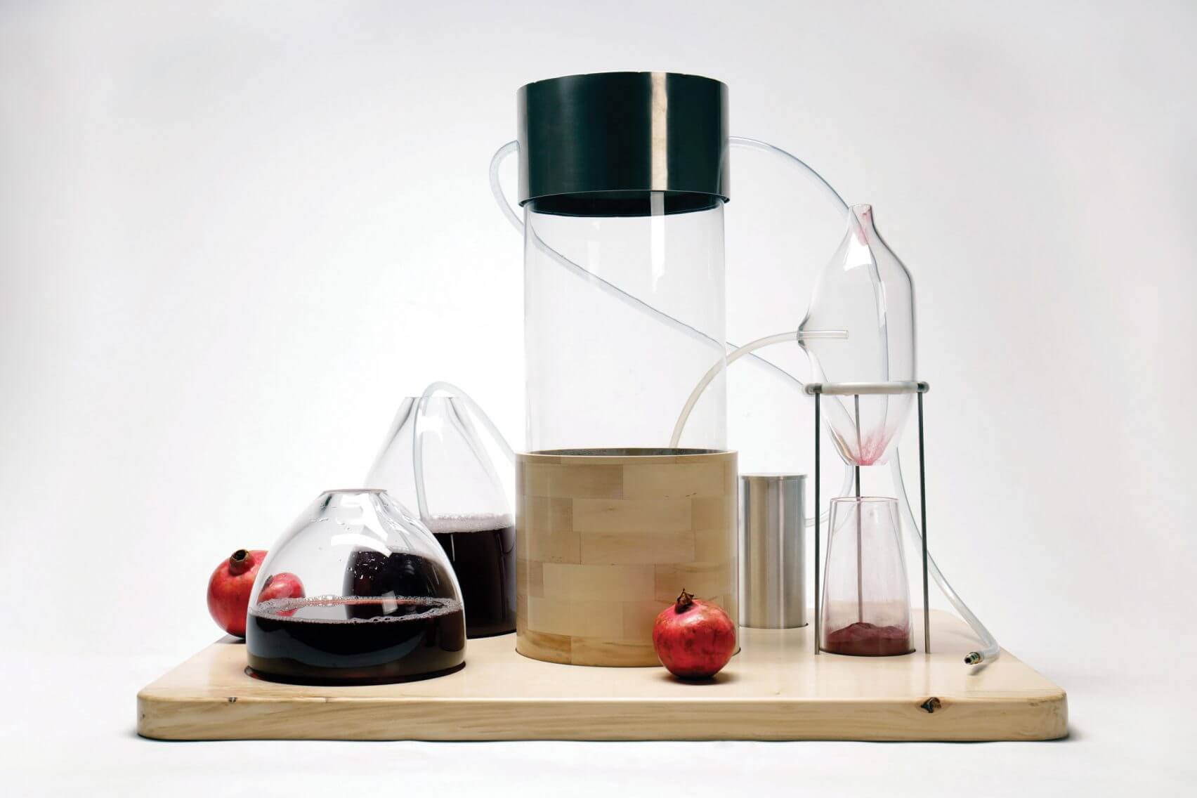
The organisation reflexlab has designed an add-on 300cc Extruder for the most common 3D printers with which biomaterial can be extruded.
In the end the bio-extruder became the winner. Since we had good memories of the Biofabricating week, we all felt it would be great to take our experience a step further and be able to 3D print with various biomaterials.
Reflexlab building plan
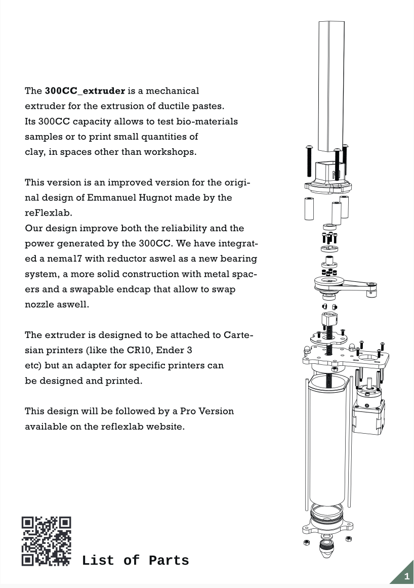
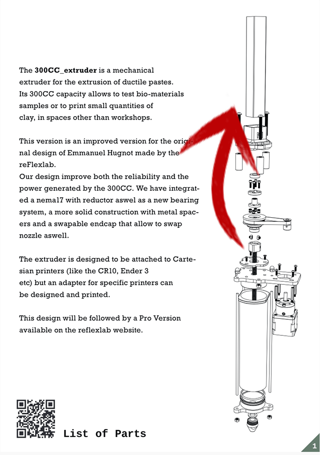
The organisation reflexlab has posted building plans for their second 300CC extruder prototype. They seem to be pretty straightfoward:
List of materials and the missing parts
Lucky us! Michelle had already printed the 3D components required. We only needed to assemble the needed hardware. So we went on a hunt in boxes, drawers, cupboards, etc.
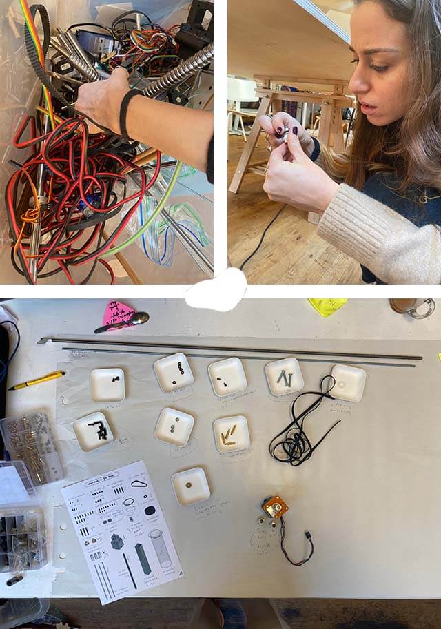
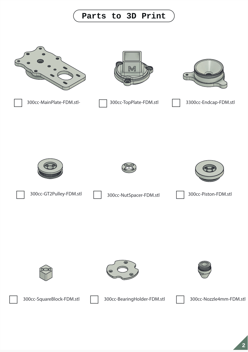
What did we have from the list of hardware materials?
| Qty | Description |
|---|---|
| 2 | Screw - M3 headless |
| 5 | Nut - M4 |
| 4 | Male female spacer - M3 |
| 3 | Screw - M3 L6 |
| 3 | Screw - M5 L30 |
| 3 | Nut - M5 |
| 12 | Screw - M3 L10 |
| 1 | Flat ring |
| 2 | Bras/Pom Nuts - d8 |
| 1 | Bore8 GT2 Pulley |
| 3 | Threaded rod - M3 L220 |
| 1 | Threaded rod - TR8 |
Ordering and shopping
What did we NOT have from the list of hardware materials?
| Qty | Description | Notes |
|---|---|---|
| 1 | Closed belt | Use open belt, close with tie rip |
| 11 | Brass insert - M3 L6 | Use alternative spacers while ordering brass inserts |
| 1 | ORing - inner d42,52 2,62 | Find alternative |
| 1 | Nema 17 Geared | Use alternative stepper motor (weaker version) while ordering Nema 17 |
| 3 | Spacer - M5 L30 | Print 3D alternative |
| 1 | Square Tube - 22x22x170 | Use alternative round tube |
| 1 | Cutted cartridge Syringe 300 cc | Order |
| 1 | Syringe plunger | Order |
| 2 | Thrust bearing - 10x18x5,5 | Buy at hardware shop around the corner |
| 3 | Smooth spacer - M5 L30 | Print 3D alternative |
We ordered the motor, brass inserts and 300CC syringe from amazon.com and hoped for the best (how would Black Friday impact the delivery date??).
Oke, at this stage, we thought we were in good shape!
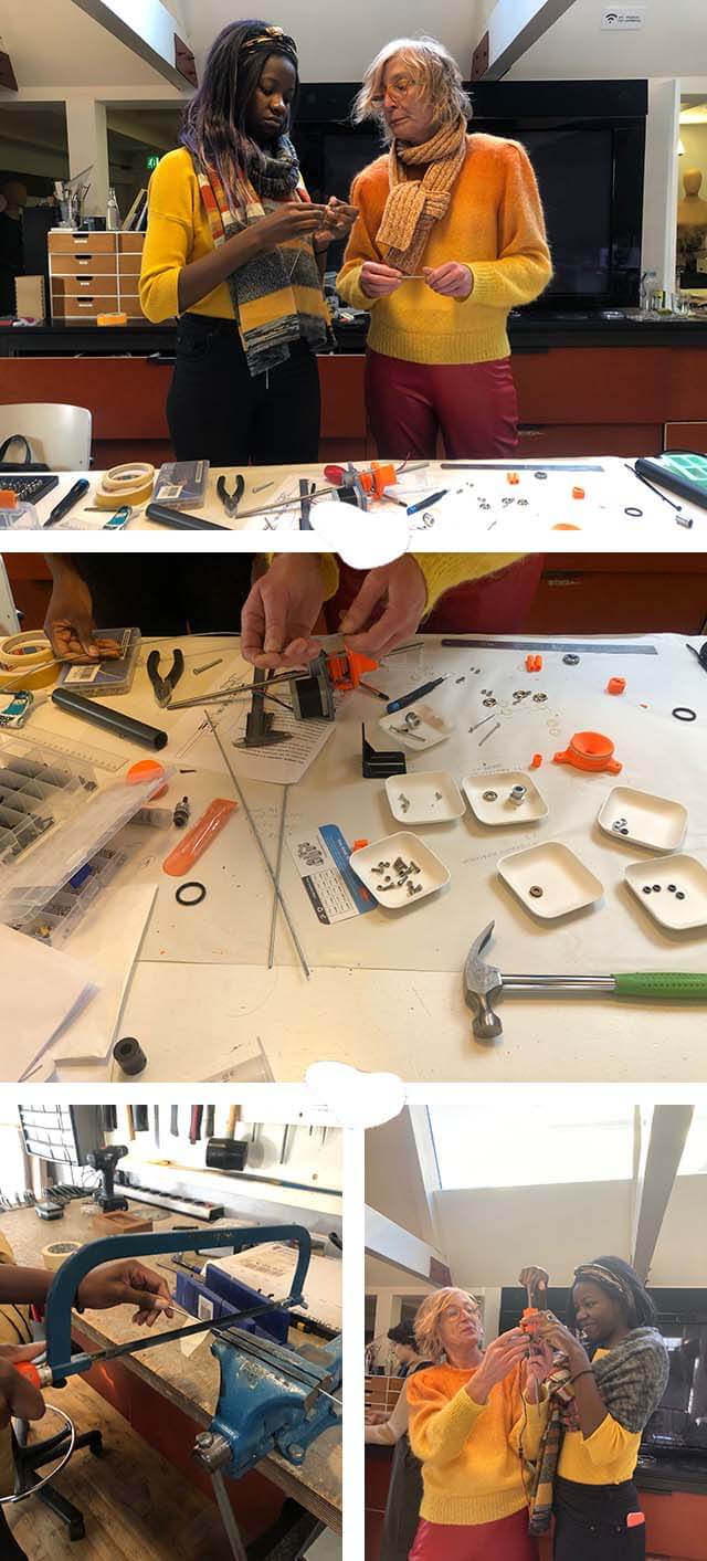
Assembling and troubleshooting
Issue 1 and 2
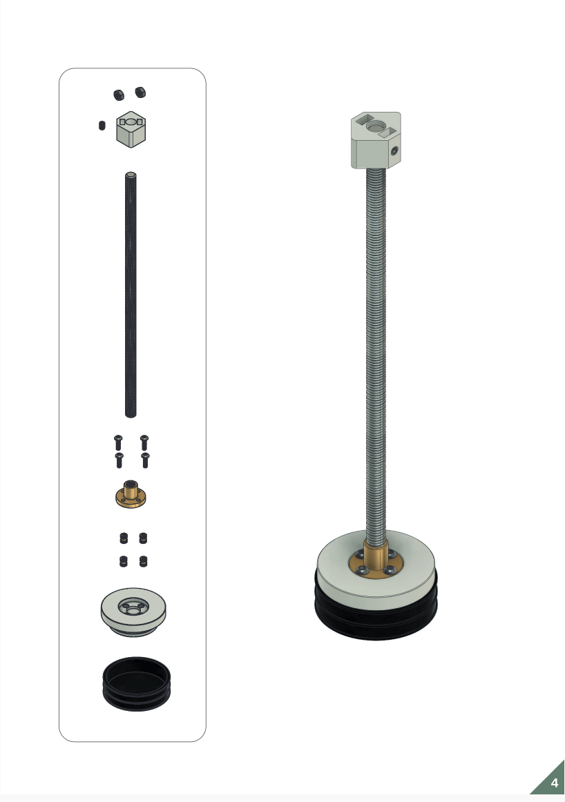
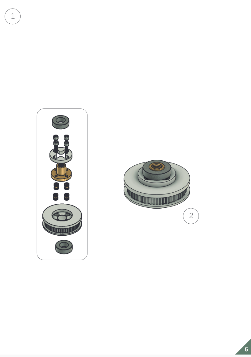
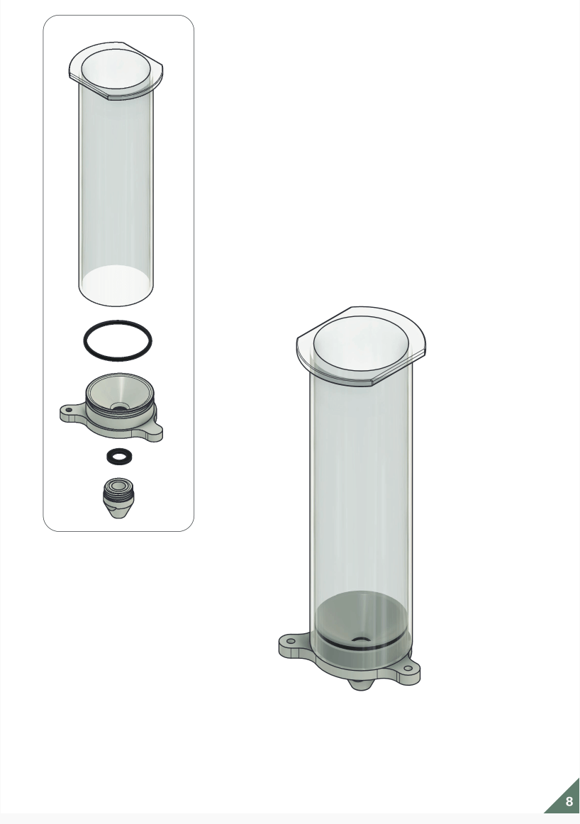
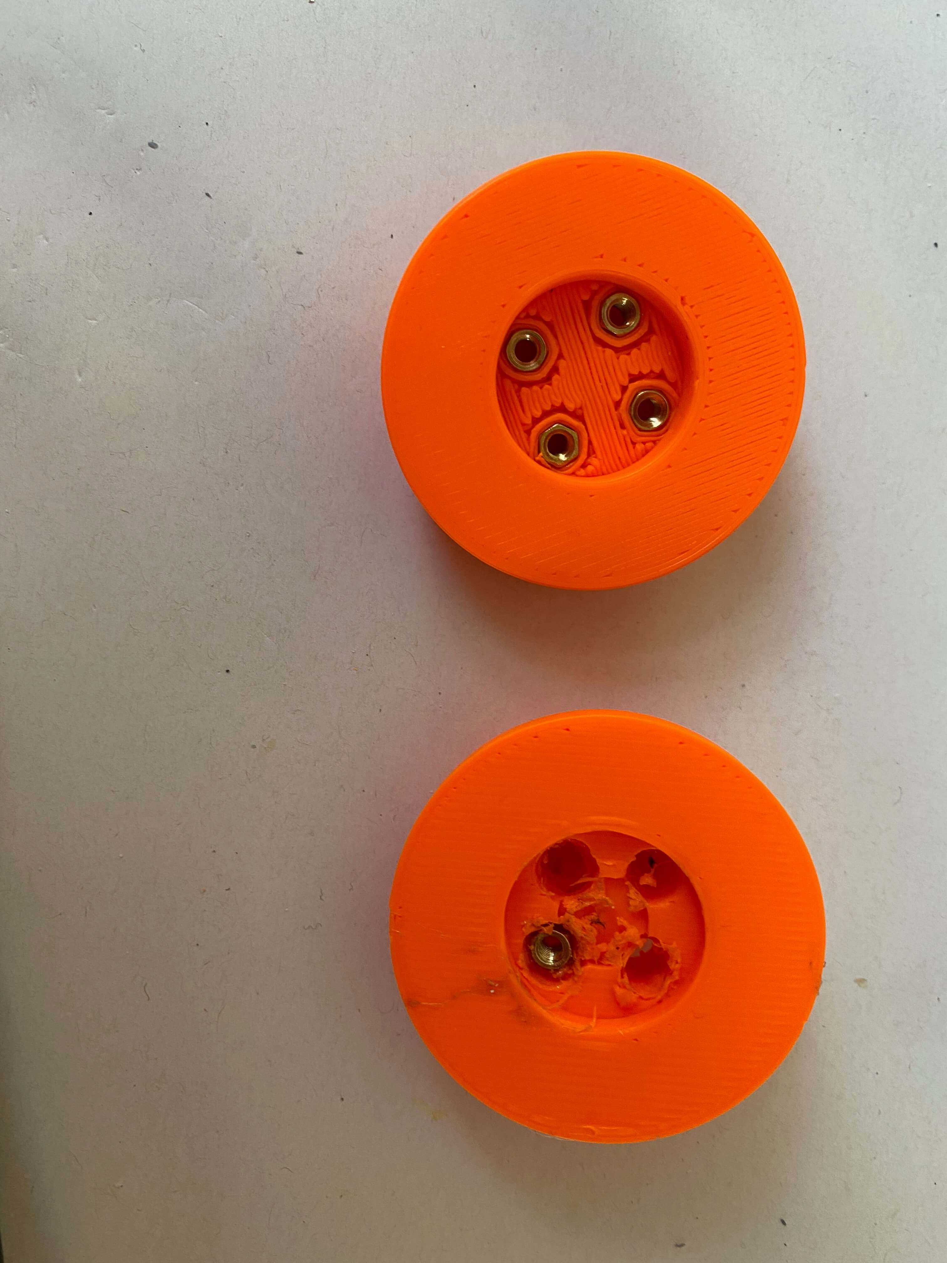
We started with the assembly of the syringe plunger (page 4) and the assembly of the wheel that would rotate the TR8 rod (page 5). First action? Put brass inserts in the 4 holes of the 3D printed components. But here we encountered an issue. Our alternative spacers did not fit in the holes.
Our first solution was to widen the holes with a drill and to glue the spacers in those widened holes. The drilling part went smoothly. But the solution to glue the spacers wasn't working. The moment we tried to screw our pom nuts to those glued spacers, they came out of the holes again. The construction was simply not strong enough.
![]()
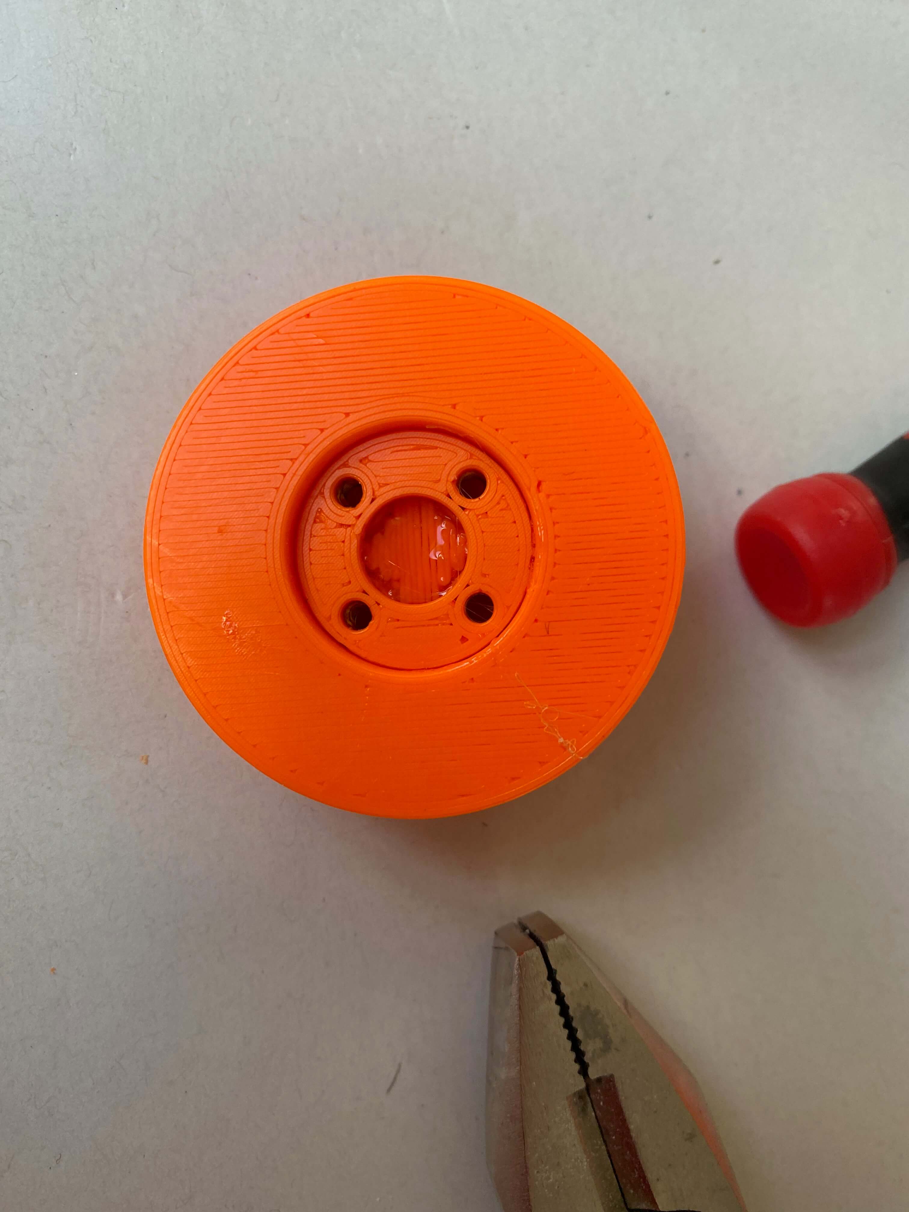
So we figured out a solution. We had to 3D print both wheels again, but then with the exact measurements for our spacers, instead of the round holes for the brass inverts. The spacers would then fit the holes. We also had to 3D print thin discs with holes for screws, that would fit on top of the wheels. Glueing those disc on the wheels, would keep the spacers in their holes, when screwing the pom nuts on there. Asli helped us out, and redesigned both wheels and the discs in Rhino. Here you can find the Rhino files.1 After 3D printing those new components, it was easy to screw the pom nuts on! First hurdle taken.
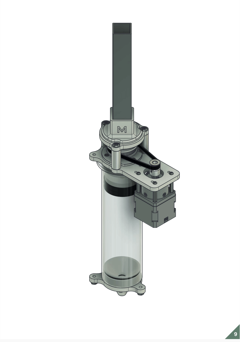
For the wheel on page 5 we needed 2 thrust bearings. They are required so that the TR8 rod which penetrates through the wheel, can smoothly rotate during extrusion. We visited a neighboring hardware store. However they did not have the right sizing bearings. So we bought some bits and bytes to come up with alternative bearings.
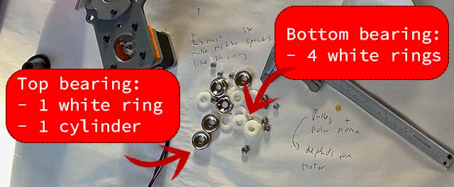
Upon testing, our solutions worked, as the rod smoothly turned in the slot of the wheel.
Issue 3, 4 and 5
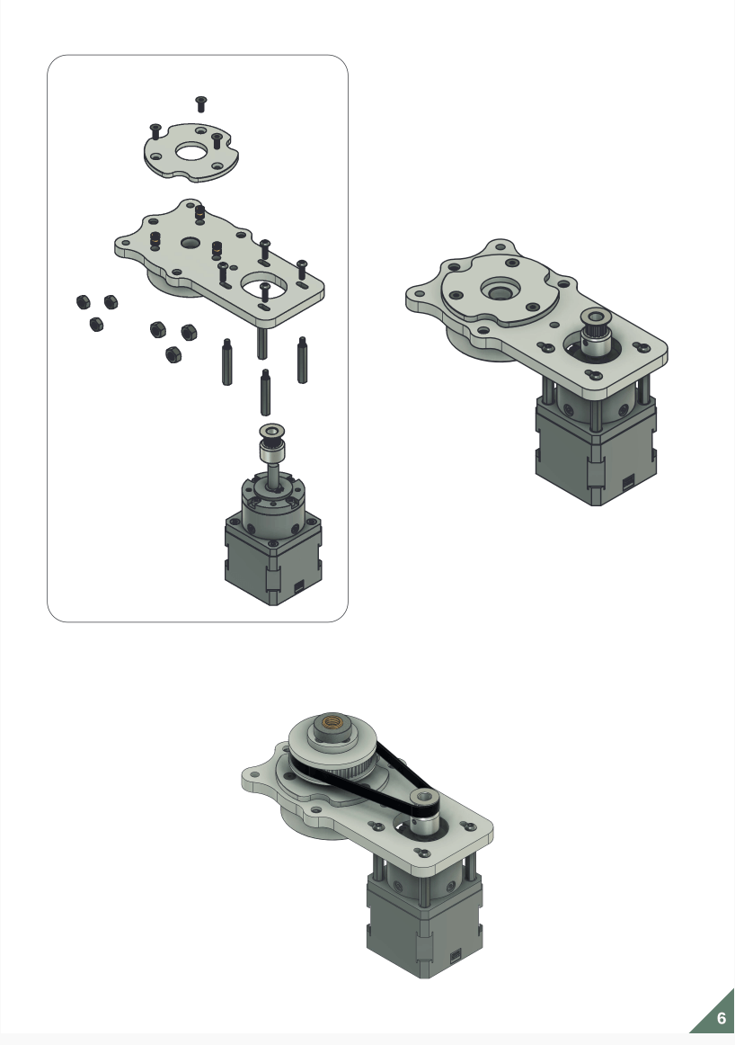
We were on page 6 of the assembly plan. Also for attaching the motor to the 3D components, the missing brass inverts were required. This time the alternative small spacers didn't cause an issue, as the design allowed us to glue a covering component on top.
Our alternative stepper motor missed the round block on top.Therefore we decided to screw the grey holder directly on top of the motor and discard the 4 M3 spacers. However, we also had to heighten the position of the pulley, to make sure that both the pulley and the wheel (around which the belt was supposed to be running) would be on the same level.
Issue 6, 7, 8 and 9
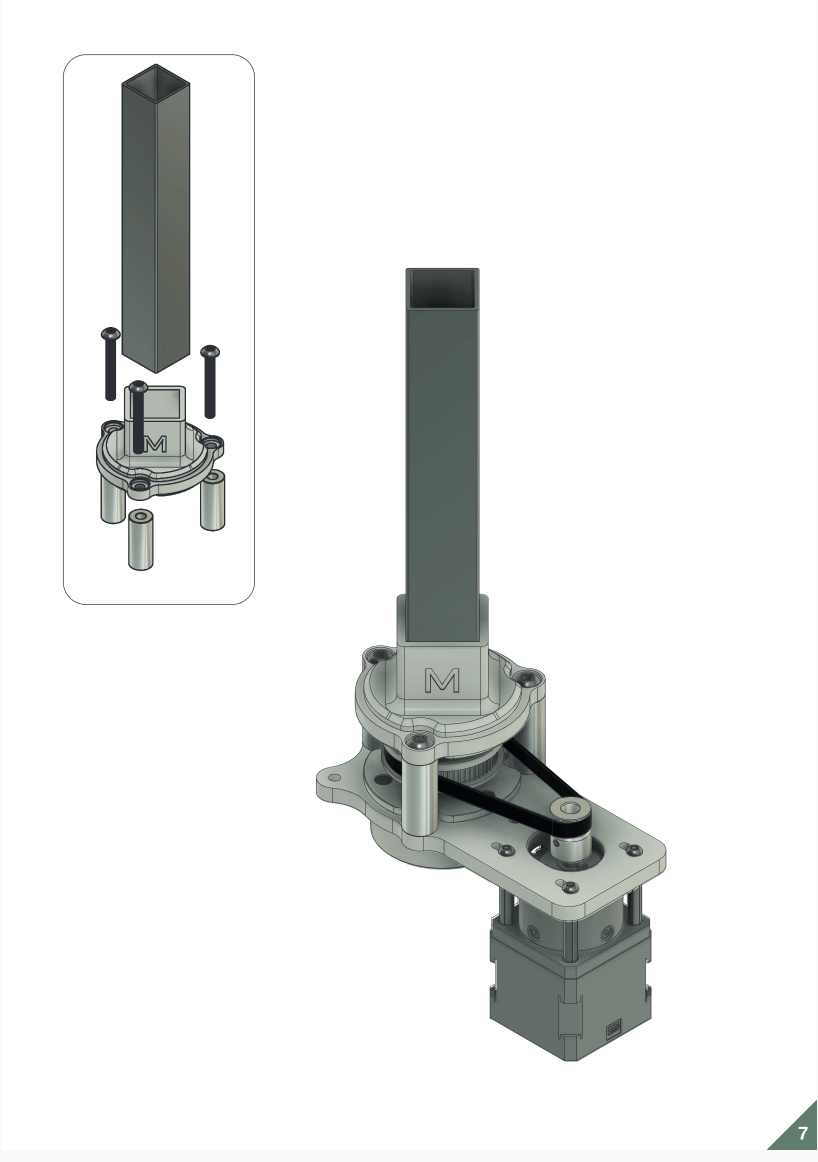
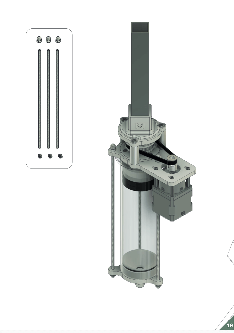
On to page 7. One way or another the 3 screws M5 L30 were too short. It seemed a mistake in the documentation. We had to use screws M5 L50. Hence we also had to reprint the 3 smooth spacers. Since we did not have a square tube, we had to use a round tube.
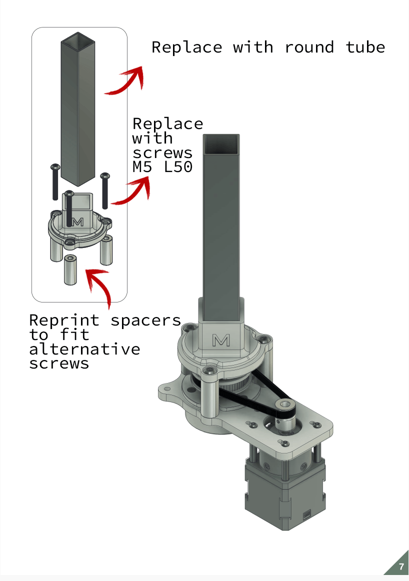
When we studied the documentation we found an additional mistake or unclarity in the plan. At first sight it looked like the stopper component had to be fixed on the TR8 rod under the rotating wheel. But that was obviously not the right position. Once the rod was penetrated throughout the whole extruder, the stopper had to be fixed on the rod completely at the top, inside the tube. But with that adaptation, our round tube didn't fit anymore. Only a square tube could hold the square stopper component. We decided we could live without a tube for our first prototype.
Issue 10
We were 2 days into assembly and only on page 8 of the plan. The package of Amazon arrived, but only the brass inverts (which we had already satisfactorily replaced with spacers) were in the package. The syringe and the motor were missing. We could do a test-run without the Nema 17 motor .... but the syringe was a requirement!
Issue 11
And then the belt on page 9. We measured off a piece of belt. Then we tried to close it with a tie-rip, but the outstanding points of the tie-rip were stuck behind the spacers as soon as we tried to rotate the belt. So we tried to close the belt by melting (no succes). And we tried to sew it (no succes). In the end we decided to connect the belt with the tie-rips, and then mill holes in the spacers, so that the outstanding points of the tie-rips could rotate undisturbed.
Issue 12
From the documentation at first instance it was not completely clear where and how to attach the assembled extruder to the printer. Our first solution was to use the motor as anchor point. We attached the back of a black extension to the printer arm. Since the motor was pretty heavy, we had to redo this multiple times with rings, etc. Then we placed the motor on top of the platform of this extension. It didn't fit as the back of the extension was in the way of the grey overhanging cap on the motor. We had to use M3 rods to fix the motor tight, but in a slightly higher position on the platform of the extension. Those M3 rods were supposed to be a simple solution. But it took a lot of patience to screw them all 4 through the motor holes.
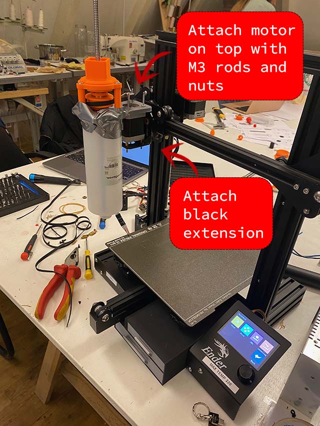
After some further research of all the reflexlab publications, we found a clearer picture on instagram. It showed that the extruder was attached to the printer arm with a special clip around the syringe. So we put on our task list to 3D print this additonal clip.
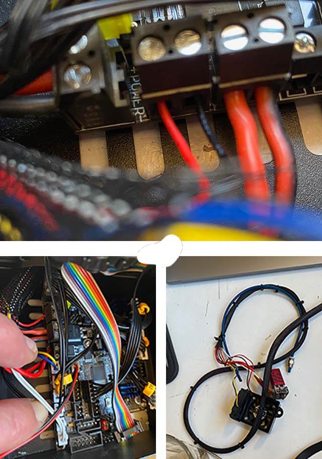
Easy peasy electronica
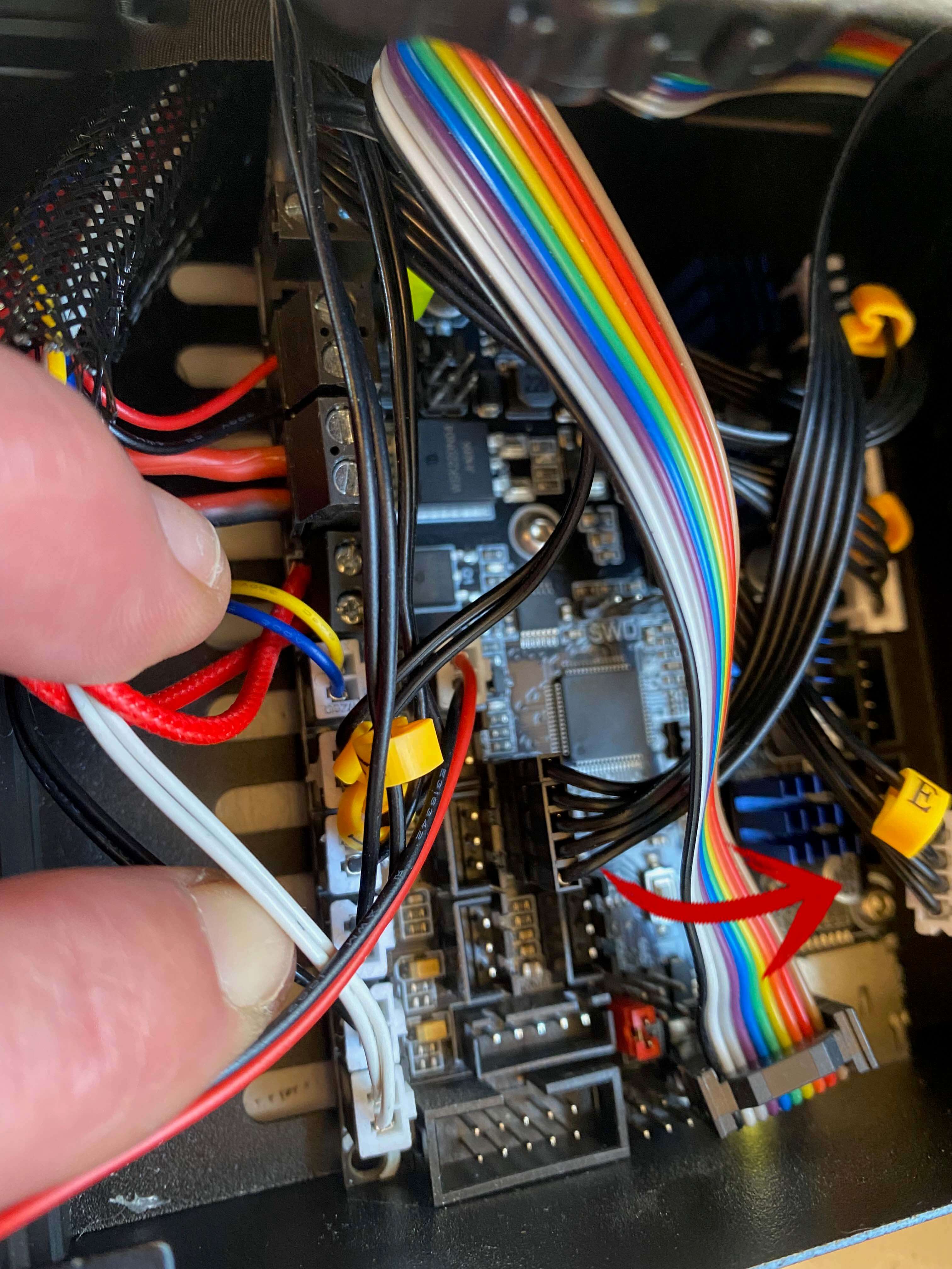
To connect the motor, we first switched off the printer!! Then we unscrewed the fan from the printer arm. After that we unscrewed the heating element with nozzle from the printer arm (leave them connected). Thereafter we opened the box in which the circuit was hidden. We followed all wiring from the fan and the heating element into the box, and disconnected all those items. On the exact same place were the heating element and nozzle had been connected (E), we connected in turn the motor of our extruder (see red arrow in photo).
Some simple tests proved that the Ender with attached extruder was functioning.
On Friday ... so far, ... not yet good
After a week of struggle we had an assembled extruder, semi-perfectly attached to the Ender 3D printer, but we still missed some crucial pieces:
- We did not have a 300CC syringe
- We had a semi-perfect motor attached semi-perfectly to the printer
- We did not have a clip to attach the syringe to the printer arm (we wanted to wait with printing till the 300CC syringe arrived to be sure about the exact measures)
From the track and trace code we knew the syringe and motor would come in next Monday or Tuesday. We could do without the Nema 17 motor for a test, since we had the (weaker) stepper motor as an alternative. But we really needed the 300CC syringe. As a backup, we could 3D print a smaller or bigger plunger and try to test with another smaller or bigger syringe by attaching it with duc-tape to the extruder. But that would be really a shoestring solution.
On Monday ... to be continued ...
We got a package ... but it was the Nema 17 motor. A nice to have, but the 300CC syringe, something we really wished for, was still on its way. We decided to try testing the extruder with a larger size syringe and therefore 3D printed a larger plunger. What we feared for did happen, the shoestring broke. All components of the extruder are sized for a 300CC syringe, so we have to be a bit more patient to test our bioextruder in real time.
Gcode
3D printers use a numerically controlled programming language made up of a series of commands called GCode. Most of these commands start with a G (hence the name), but there are also some common machine-specific codes that start with an M. These commands tell your 3D printer exactly what actions to perform – where to move, what speed to use, what temperatures to set, and much more.
The GCode files are generated in Slicer programs like PrusaSlicer and Ultimaker-Cura.
However, since we were at about to hack the Ender printer, we would have to adapt the GCode files which we would use to print with biomaterial. You can view and edit the contents of a GCode file by clicking “Save Toolpaths to Disk”, selecting a location for the file on your hard drive, and then opening the .gcode file in a text editor like Notepad or in a free website like ncviewer. You can also write your own GCode commands from scratch in Notepad or ncviewer. Once you are ready, save them to your drive and overwrite the extension with the extension .gcode.
The most commonly used GCode commands are:
- G28 – Perform Homing Routine
- G90 and G91 – Set Positioning Mode
- G1 – Linear Movement
- G92 – Set Current Position
The most important variables in the GCode lines are:
- X - Position on X-axis
- Y - Position on Y-axis
- Z - Position on Z-axis
- E - Extrusion flow rate
- F - Speed of nozzle movement
For example the GCode line:
- G1 X30 E10 F1800;
Means:
- Push 10mm of filament into the nozzle while moving to the X=30 position with a speed of 1800 mm/min at the same time
In the documentation of reflexlab they stated:
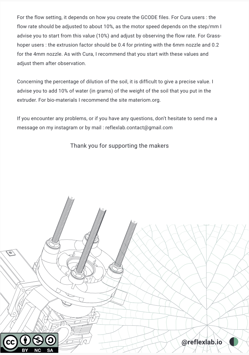
"For the flow setting, it depends on how you create the GCODE files. For Cura users : theflow rate should be adjusted to about 10%, as the motor speed depends on the step/mm Iadvise you to start from this value (10%) and adjust by observing the flow rate. For Grass-hoper users : the extrusion factor should be 0.4 for printing with the 6mm nozzle and 0.2for the 4mm nozzle. As with Cura, I recommend that you start with these values andadjust them after observation."
In other words, when printing biomaterial with the their 300CC bioextruder attached to the Ender, the extrusion flow rate (E) most likely had to be adapted. In order to test this flow rate, we created a simple GCode test file, in which the flow rates were varied, while the printer would extrude a simple square of 3 layers high.2
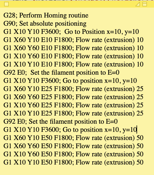
The moment our extruder is finished, we will be able to study the flow rates with this test file. For the moment it was fun to give our written GCode file a dry-run. At least after the dry-run we knew the electronic circuit was still oke and the GCode commands had no errors.
Dry-running the GCode test file
In order to generate the GCode file for our lady, we used PrusaSlicer. In this program, in the menu option "Configuration assistant" we created a new printer with the following settings:
- Firmware - Marlin (legacy)
- Bed x 210 mm and y 250 mm (we used the bed from the PrusiaSlicer)
- Nozzle diameter 4 mm width
- Filament diameter 4 mm width
- Extrusion temperature 0 degrees celcius
- Bed temperature 0 degrees celcius
For slicing our model, we adhered to the following settings:
- Thickness first layer 2 mm
- Thickness other layers 1.5 mm
- No brim and skirt
- Diameter filament 4 mm
- Extrusion multiplier 0.2 (advise reflexlab)
You can find the GCode file for the lady here.3
Although our extruder didn't work yet, we already could review, run and test our commands on the ncview website:
Testing GCode file of lady on ncview website
Testing recipes for biomaterials
While assembling the extruder, we also were playing around with biomaterial recipes. The challenge was to obtain a biomaterial which was liquid enough to pass the nozzle upon extrusion, but also solid enough to not leak prematurely and to keep its form, once extruded.
Recipe 1
We first tested a mixture based on guar gum, according to the below recipe. Guar gum is a polysaccharide extracted from guar beans that has thickening and stabilizing properties useful in food, feed, and industrial applications.The guar seeds are mechanically dehusked, hydrated, milled and screened according to application. it has almost eight times the water-thickening ability of other agents like cornstarch) and only a small quantity is needed for producing sufficient viscosity. In addition to guar gum's effects on viscosity, its high ability to flow, or deform.
* 8 gr guar gum
* 7 spoons of oyster shell
* 200 ml water
* Golden Green powder color
* Measuring cups
* Bowls
* Spoons
- Handmixer
* Combine all ingredients in a bowl
* Mix them thoroughly with the handmixer
The original recipe calls for 7 spoons of filler (oyster shell). But with this ratio of ingredients, the liquid's viscosity was too low. After 2 days of drying the mixture had flattened out.
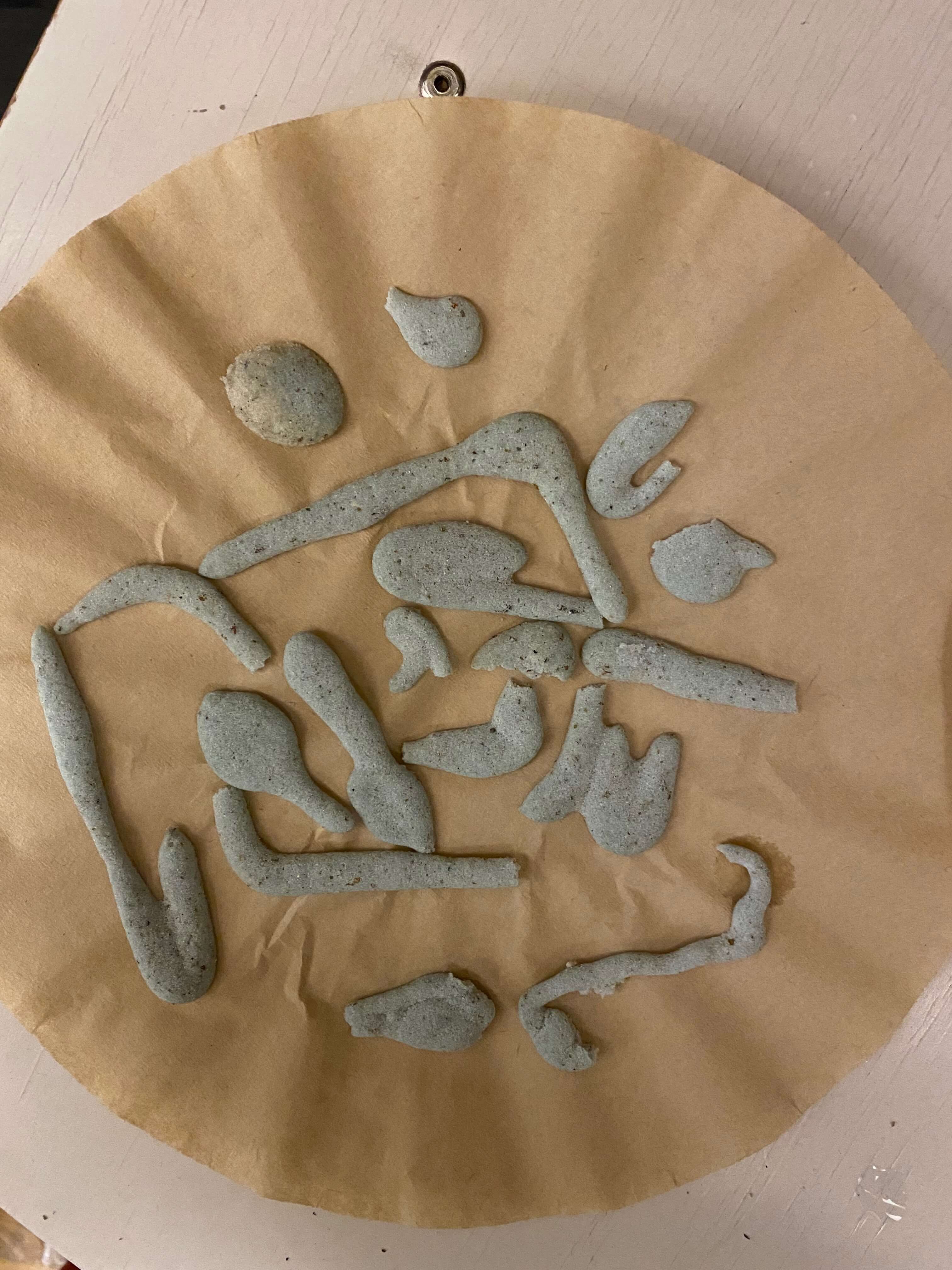
But when we increased the oyster shell filling to 15 spoons and added an additional 7 gr of xanthan gum, the mixture became quite right. On the start it had a consistency of wet sand, and it dried without any air bubbles and with a clean and smooth surface.
Recipe 2
We liked the effect of xanthan gum, so we decided to make a mix solely based on xanthan gum. Xanthan gum is a polysaccharide with many industrial uses, including as a common food additive. It is an effective thickening agent, emulsifier, and stabilizer that prevents ingredients from separating. It can be produced from simple sugars using a fermentation process.
* 8 gr xanthan gum
* 56 gr oyster shell
* 12 gr sugar
* 10-30 ml water
* Measuring cups
* Bowls
* Spoons
- Handmixer
* Combine all ingredients in a bowl
* Mix them thoroughly with the handmixer
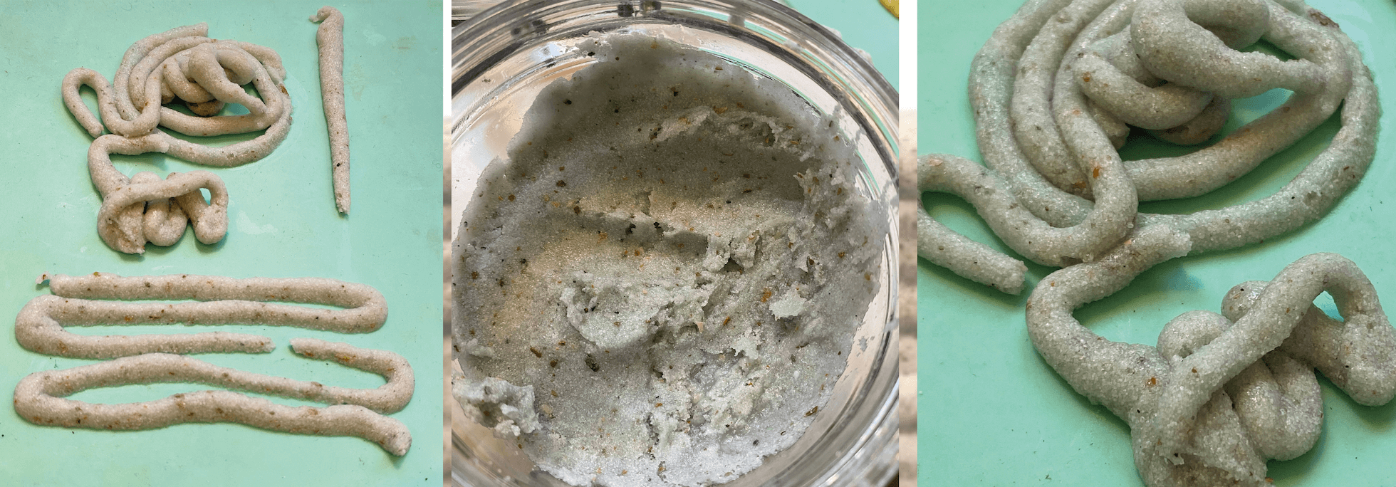
This seemed to be a good mix too. Liquid enough for extrusion, but thick enough to be not deformed while drying. On the start it had a consistency of wet sand, and it dried without any air bubbles and with a clean and smooth surface.
Recipe 3
On to some further testing with xanthan gum. We reduced the amount of filler (oyster shell) and increased the amount of water.
* 8 gr xanthan gum
* 8 spoons of oyster shell
* 150 ml water
* Golden Green powder color
* Measuring cups
* Bowls
* Spoons
- Handmixer
* Combine all ingredients in a bowl
* Mix them thoroughly with the handmixer
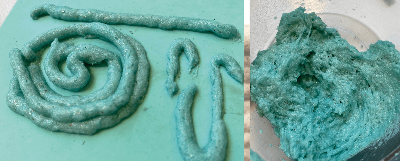
This mixture was completely different from the previous 2. This felt and looked like fluffy play-doh and was full of air bubbles, also after drying. We liked the color, but not so much the consistency.
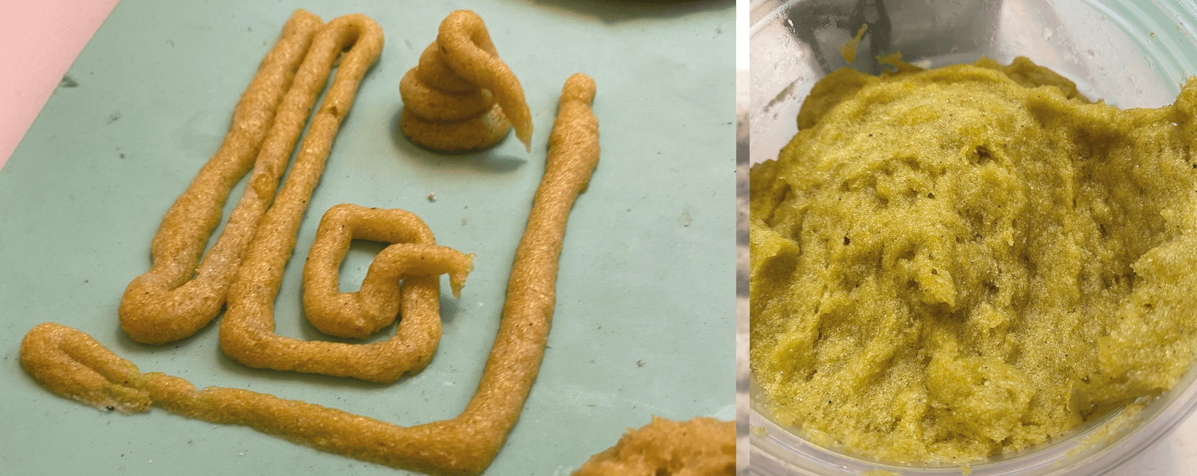
Recipe 4
Hereafter we tested a mix of xanthan and guar gum. We reduced the amount of filler (oyster shell) and increased the amount of water.
* 12 gr xanthan gum
* 8 gr guar gum
* 200 gr of oyster shell
* yellow food coloring
* Measuring cups
* Bowls
* Spoons
- Handmixer
* Combine all ingredients in a bowl
* Mix them thoroughly with the handmixer
This mixture has still the fluffyness of the third recipe, but by increasing the filler and reducing the amount of water, it became more solid and had a slightly smoother surface.
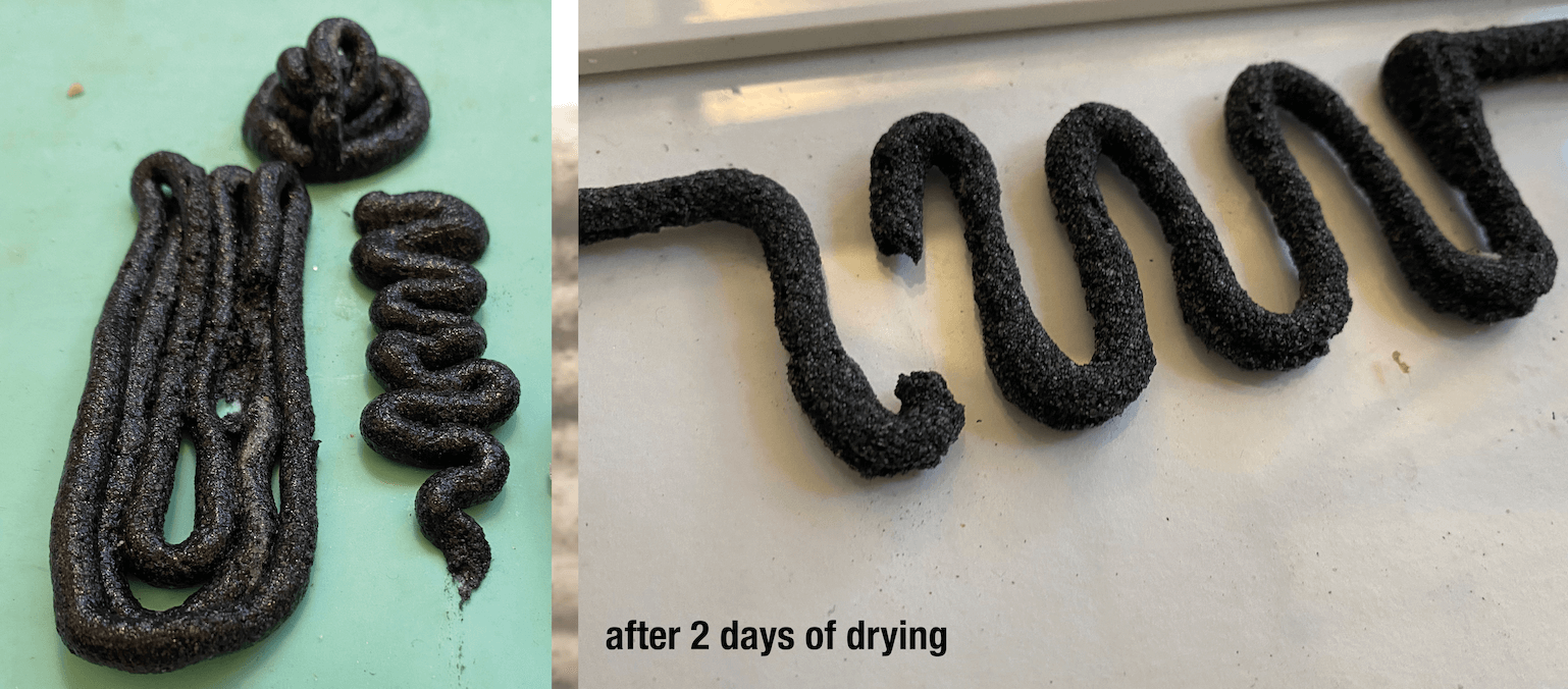
Recipe 5
We liked the consistency and surface of recipe 2, therefore we went back to a mix based on xanthan alone and used this time charcoal and oyster shell as fillers.
* 10 gr xanthan gum
* 4 spoons of grinded charcoal
* 10 spoons of oyster shell
* 100 ml water
* Measuring cups
* Bowls
* Spoons
- Handmixer
* Combine all ingredients in a bowl
* Mix them thoroughly with the handmixer
Maybe due to the higher amount of water, the mixture had more air bubbles and was not as smooth as we had liked. Although we loved the dramatic black color.
Recipe 6
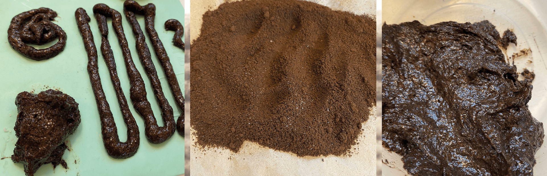
Last but not least, we used again xanthan gum, but instead of oyster shell as filler, we applied ground coffee as filler.
* 8 gr xanthan gum
* 7 spoons of coffee powder
* 150 ml water
* Measuring cups
* Bowls
* Spoons
- Handmixer
* Combine all ingredients in a bowl
* Mix them thoroughly with the handmixer
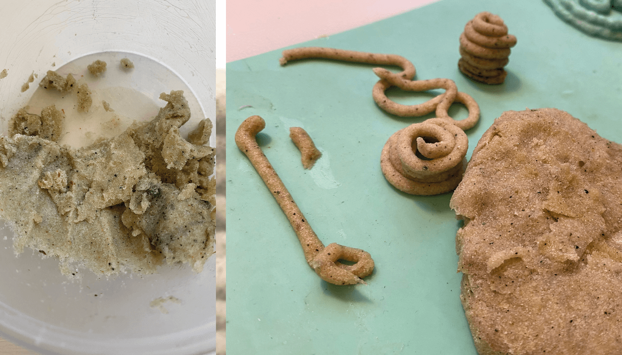
The mixture seemed at first sight full of water and very fluffy, but upon drying showed a good balance in viscosity.