13. Skin Electronics
Inspiration?
The last week of our assignments, time for skin electronics. Coincidence or not, this week I just got my new hearing aids. As such I already feel plastered by skin electronics. Or even worse, I feel completely invaded, uglified, and overwhelmed by skin electronics.
Invaded because the earmolds of my hearing aids sit inside my ear canals and concha bowls and close them off completely to provide an acoustic seal for the electronic sound my speakers are piping inside.
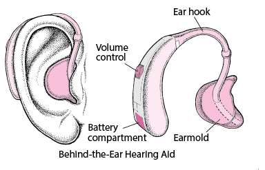
Uglified because my new hearing aids look like medical devices made out of beige plastic the color of Crayola’s old flesh-colored crayon. That color (discontinued decades ago) was supposed to resemble the skin shade of white people, but it looks totally unnatural when worn behind the ear no matter what your skin color is. The first few hours, the ugly design wasn’t an issue for me, because I can hear better than ever before! But think about it. Why would anyone design an ugly piece of beige plastic that looks like a medical device with a clear tube stained by earwax? There is absolutely no reason why manufacturers can’t make hearing aids look attractive as any other type of body adornment. So manufacturers, please get away from that "mechanical ear" design and embrace a "beautiful ear" design. It is just like artist Elana Langer says:
"Having hearing aids be just as beautiful as earrings, feels like a celebration of life and what we can do, instead of a chore and embarrassment and a reminder of what we lack."
Alas, that vision has yet to be embraced by many aid manufacturers.
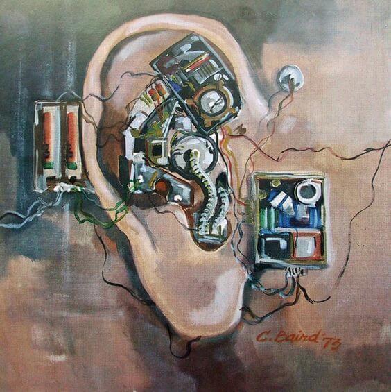

Left: painting Mechanical Ear by Chuck Baird
Right: hearing aid designed by artist Elana Langer
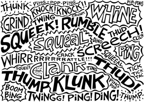
Overwhelmed because I hear everything and everything and everything. The rustling of paper, the clicking of heels on the ground, the squeaking and creaking of a door. It is just one big cacophony!
How different from last week. Then I had to ask over and over: "Sorry, what did you say, can you repeat yourself?" Now I would like to beg everyone: "Please, be quiet, don't make so much noise!"
My hearing care professional tells me this is just a phase. My brains need to be trained again to properly filter out the relevant sounds from the clutter. And this training time could last up to 3 months. It is fine with me. But not without some protection. So I decided to make an 'automatic warning system' for my environment. When everyone around me gets too noisy, my warning system will tell them TO SHUT UP.
Since my particular hearing aids are unattractive pieces of technology, still designed from the perspective of the "mechanical ear", I decided that the design of my warning system would echo this perspective. No hiding of the cables and electronic components. No beauty and elegance. On the contrary, I will put all the uncharming ugliness of my warning system in the open, for everyone to see. Even better, I will exaggerate the technicality of the warning system, by using a tangle of long cables and big components. Because in the end, both my hearing aids and the warning system, are then just solely designed from a functional perspective. Certainly not a celebration of life, but a design as a reminder of what I lack.

Final Result
Functional devices
"Please decrease your tone, say no more"
Warning system with light and sound
Process and workflow
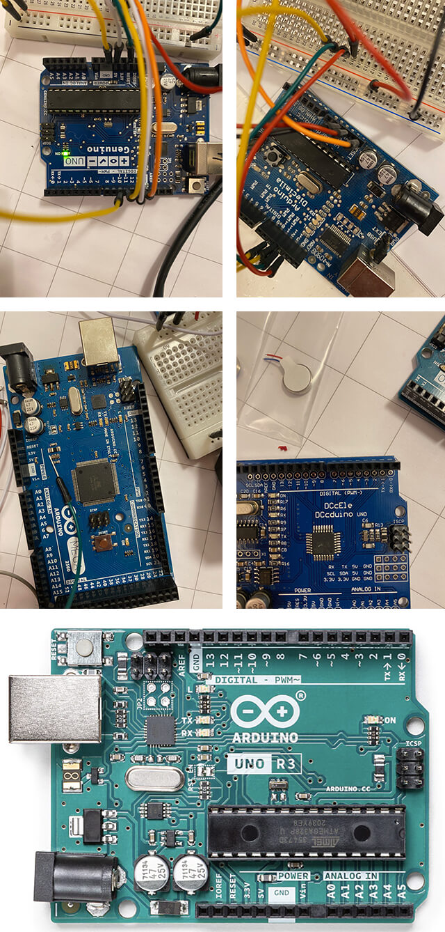
Troubleshooting boards
This week my main challenge was my computer. I learned that Mac computers and Arduino boards are not always compatible. Before I could focus on the building of the circuit, I first had to get my Arduino to blink. In the lab in Amsterdam there are several boards around. Unfortunately I picked exactly the wrong order with the boards. First I connected the Genuino board. After endless plugging and unplugging, trying different cables and USB ports, I decided the Genuino board was just not compatible with my Mac. Then I tried the Diecimila board, with the exact same end-result. On to the Mega board, same issues. And also the DCcDuino board did not come alive when connected to my Mac. Only when I finally used the Uno board, I got a blinking LED.
Preparing the ATtiny85
Microcontroller
For portable applications like a skin electronic project, an ATtiny microcontroller is a great match. But getting the code onto it's chip can be a little bit of a challenge. One of the more convenient ways to load code onto the ATtiny is through a special program called a bootloader. This program sits on the microcontroller and listens for incoming instructions, and then writes new program information to the microcontroller’s memory. With help of the bootloader program, you’ll be able to load code from your Arduino IDE onto the ATtiny using a USB connection. This means that you won’t need to remove the microcontroller from your circuit in between programming rounds. Burning a bootloader is something that you only need to do once.
Uploading support
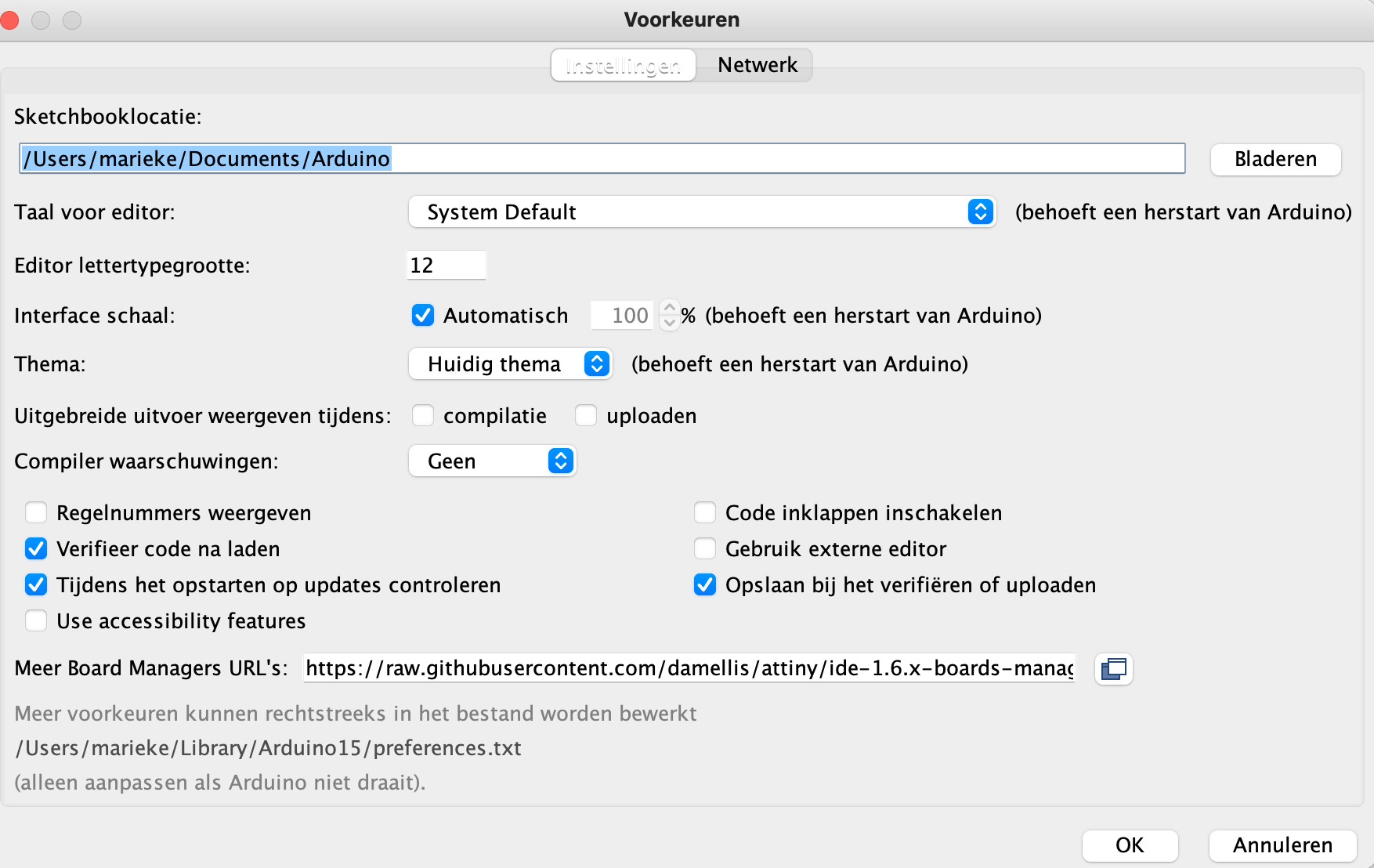
First we have to upload support for the ATtiny:
- Select in the Arduino Ide the Additional Boards Manager option
- At the bottom of the preferences window is a space to enter Additional Board Manager URLs
- Enter the following link before clicking ‘OK’:
https://raw.githubusercontent.com/damellis/attiny/ide-1.6.x-boards-manager/package_damellis_attiny_index.json
- Select and install the package from the Boards Manager
- The microcontroller becomes visible under the ‘boards’ list.
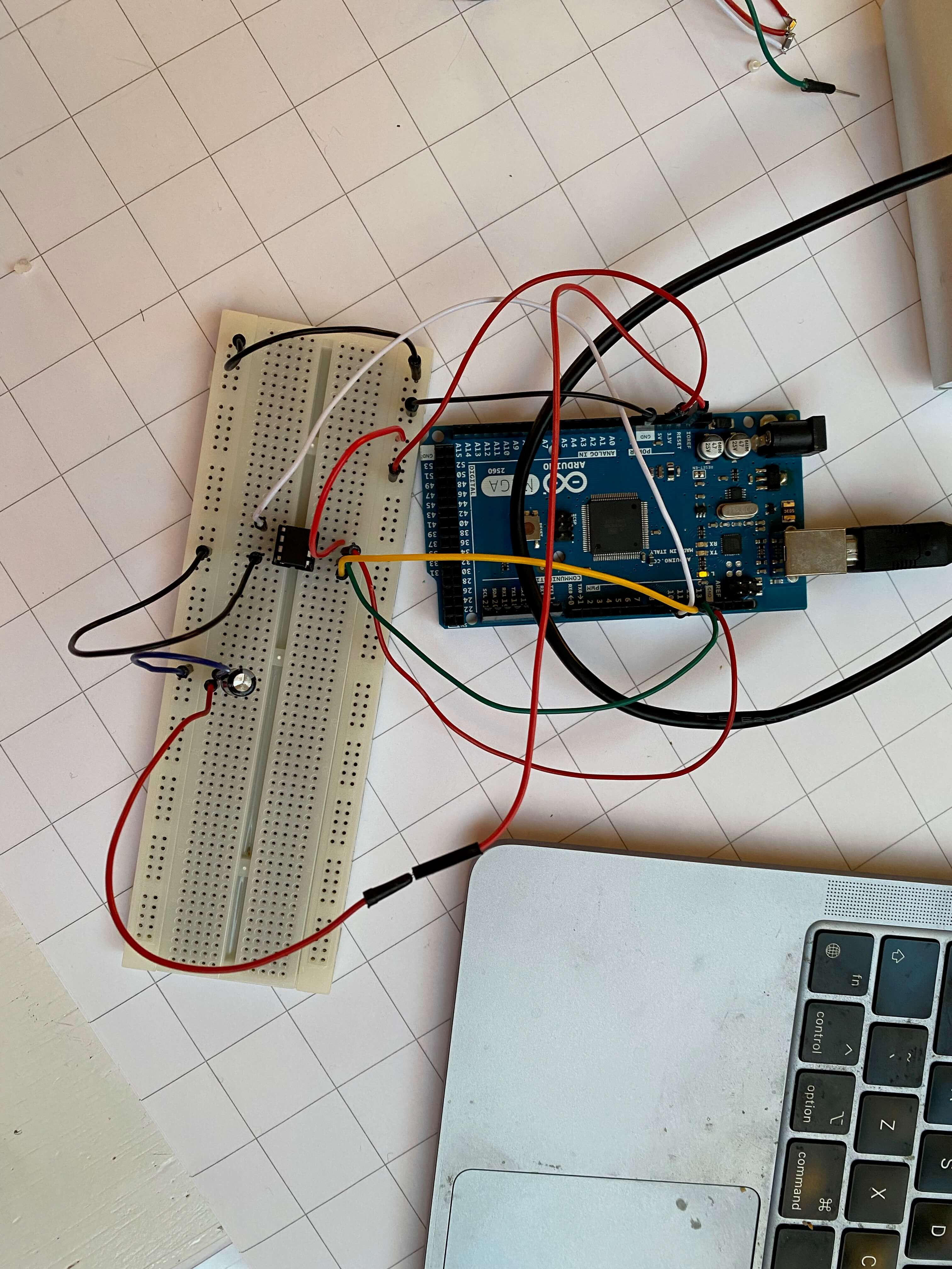
Wiring the ATtiny
The bootloader can be uploaded by using an Arduino board as an ISP, or In-System Programmer. Technically this means wiring two devices together so that any instructions passed to the chip of the Arduino are also sent out to the ATtiny. I used an Arduino Uno and the ATtiny85. The ATtiny has a direction based on the little circle it has engraved, that part is up.
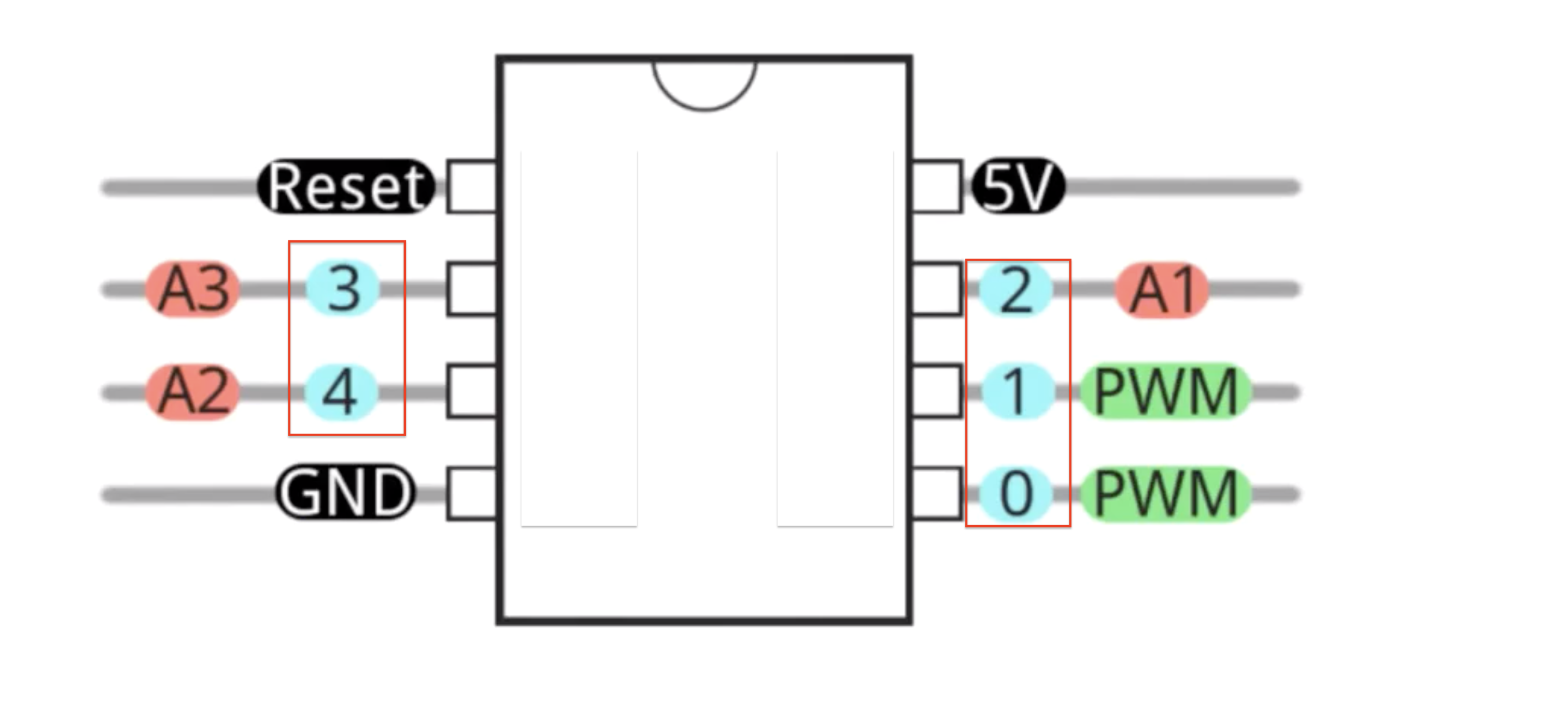
Alongside ground and voltage, I connected the pins as following:
- ATtiny 2 with Arduino 13
- ATtiny 1 with Arduino 12
- ATtiny 0 with Arduino 11
- ATtiny Reset with Arduino 10
- Put a small (10uF) capacitor between the reset and ground pins
Burning the bootloader
Now everything is set to burn the bootloader:
- Tools > Boards > ATtiny 25/45/85
- Tools > Processor > ATtiny 85
- Tools > Clock > Internal 8Hz
- Tools > Programmer > Arduino As ISP
- Tools > Burn Bootloader
The ATtiny was now prepared for further coding. However, prototyping of a circuit can be better done with help of an Arduino board. Only when the prototype is ready, as a last step, the ATtiny is integrated. Therefore I set my prepared ATtiny aside for the moment, and continued with the Arduino Uno as board.
Circuit and components
There are a lot of Arduino sound sensor examples on the internet. In the end I used two project examples for my first ideation.1, 2 I first made a sketch of the circuit.
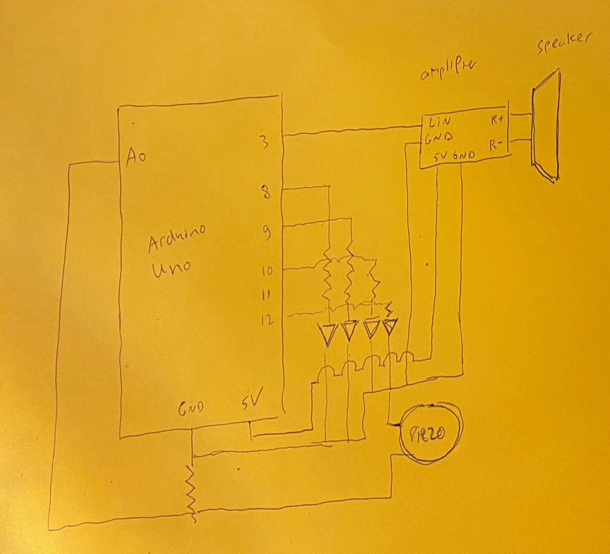
The following components would be included in the warning system circuit:
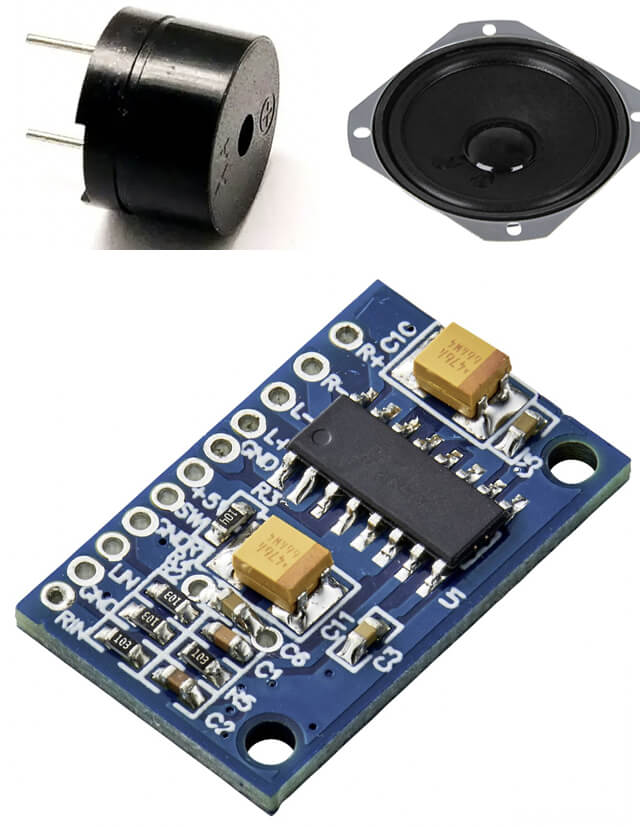
- Piezo buzzer that can detect sound
- Joy-it Com-Loudspeaker01 connected to a Tru Component TC-9072564 Amplifier
- 4 red LED lights
- 9V Battery
- Many, many jumper cables
The circuit is not too complicated:
- The piezo buzzer is connected to ground and via a 1MΩ resistor to pin A0 on the Arduino
- The Joy-it Com-Loudspeaker01 is connected to the R+ and the R- output ports of the Tru Component TC-9072564 Amplifier
- The GND and LIN input ports of the amplifier, are connected to GND and pin 3 on the Arduino respectively
- The GND and +5V power ports of the amplifier, are connected to 5V and GND on the Arduino respectively
- Red LEDs for visual indication are connected through 200Ω resistors to pins 8, 9, 10, and 12 and GND on the Arduino
But I decided to built it step-by-step, testing the functioning of every component along the way.
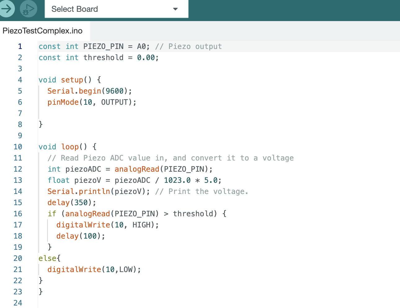
Testing piezo buzzer as sound sensor
I first made a simple circuit with the piezo and one red LED. In first instance the piezo was not sensitive enough to respond on varying sound levels. I tried to alter this by changing the resistor value from 1MΩ to 10MΩ, and hooking up an additional amplifier. However that didn't improve matters. But then I found a great tip about changing the code to increase the piezo sensitivity.2 And that worked brilliantly. The crude code translates every seperate vibration into a voltage reading. However, the sensitive code reads out a string of vibrations, and only selects the peak reading from that string. In this way the piezo buzzer becomes way more sensitive.
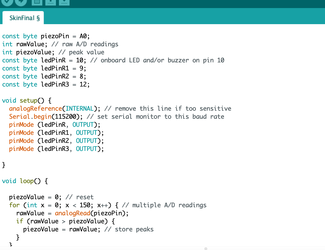
Sound sensitive piezo
Talkie
Time to focus on the speaker. For the prototyping I worked with a smaller speaker in first instance. First I tested the speaker stand-alone to check if it functioned properly. It produced no sound. Then I connected the speaker to the Arduino board through an amplifier. No sound. I was puzzled, till I noticed that the amplifier needed powering. That solved it, as my speaker started to produce tones loud and clear.
Now it was time to decide what sound elements my warning system would play. There are several ways to produce sound with Arduino.
In week 5, during the E-textiles week, I used the Tone library in Arduino. The Tone function can generate notes and melodies. I felt that a friendly melody was not a real fit for a warning system.
The DFPlayer Mini MP3 Player for Arduino is a small and low priced MP3 module with an simplified output directly to the speaker. The module can be used as a stand alone module with attached battery, speaker and push buttons or used in combination with an Arduino board, and can play MP3 and WAV files, which can be recorded on beforehand. This seemed a better option for the warning system. But at the same time, it felt too personal. If I would record a message, which would be played every time it was too noisy, it would be almost like I would speak up myself in those situations. And I felt I wanted to bring distance between myself and the functioning of the warning system.
Then I found the Talkie library for Arduino. The Talkie library allows a sort of text-to-speech, although it is restricted, since it is a preset vocabulary of around 1000 words and not true text-to-speech. There are several lists of words that fall under the Talkie library. It is based on the old technology of the voice synthesizers of the 1980s. The library stores sound files in a linear predictive coding (LPC) format, and uses an Arduino board to act as the voice synthesis processor (VSP).3 The end result is exactly what I envisaged for my warning system, a very muffled, robotic male voice, which is alienating and soothing at the same time.
To use Talkie in your own code, all you need to do, as shown below, is:
- Download the Talkie library
- Include the Talkie header file
- Include one or more Talkie lists
- Declare a variable of type Talkie
- In the body of your code, call the "say" function
Some hints and tips while using Talkie:
- Talkie currently supports the Uno and Nano boards, the MEGA 2560 board, the Leonardo and CircuitPlaygound boards, the SAMD and Teensy and Particle boards.
- Porting to ATtinys is not possible, since they lack the hardware multiplication
- For the Arduino Uno the Talkie library automatically enables pin 3 for normal sound, and pin 11 for inverted sound. You do not need to define this in your code. You can connect your speaker only to pin 3, or attach the speaker between pin 3 and 11 to increase volume. If you do not use pin 11 for the speaker, it is advisable to not use the pin at all, since it will be occupied by Talkie.
- You cannot mix the Talkie and Tone libraries. Only after a call to say...() you can use tone() again.
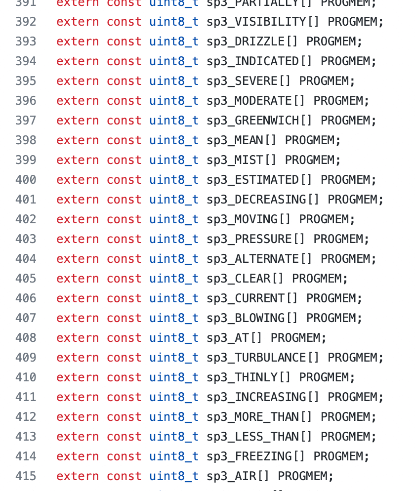
The lists of words in the Talkie library are mainly related to rocket science, the flight industry, and weather related.
When testing, I also noticed that some words became too muffled and could not be understood. Unfortunately this was the case for the words "voice" and "lower", which would have been a nice fit for my warning system.
So it took me some fantasy to make an intelligent sentence for the warning system. The best I could do, by using words from different lists:
"PLEASE DECREASE YOUR TONE, SAY NO MORE"
Talkie talking
Code
The Talkie library is not compatible with the ATtiny. But I really loved the effect of the robotic voice. So the ATtiny85 I had prepared earlier went back in the drawer. I would have to use the Arduino Uno board in my final project. In the end I didn't mind that much, as I had already envisioned in my design that I would use a lot of jumper cables and large electronic components, in order to stress the pure functional perspective of the warning system.
It was time to pull it all together. So I expanded the circuit with a total of 4 red LEDs, connected to pin 8, 9, 10 and 12 (not 11 since that one is occupied by Talkie). And I replaced the small speaker with a real serious big speaker, the Joy-it Com-Loudspeaker01.
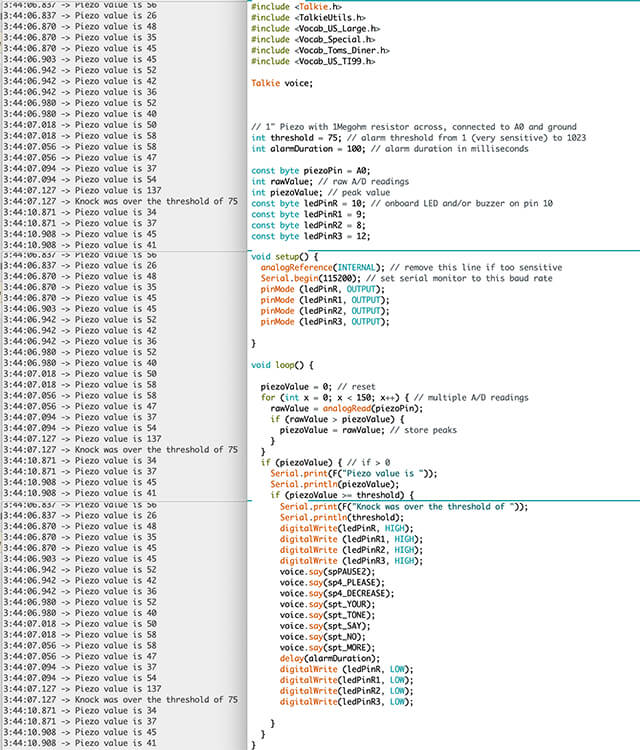
I used the piece of sensitive piezo code, and included the Talkie library as well. I had to test a bit with the threshold. When would the warning system have to get into gear? When testing it was clear that the threshold for the system, laying quiet on the table, was different than for the system, bundled around my neck. The good news was that the final system still contained my Arduino Uno board. So while I had already placed it around my neck, like a sort of ugly necklace, I could still plug in the computer, to read off the piezo values of the serial monitor. In the end I decided on a threshold piezo value of 75. Below this value, everything was nice and bearable for me while wearing my hearing aids. Above that value, the noise around me started to be unpleasant, so then my warning system had to act!
The final code:
Going live
The Arduino Uno board would be part of the final project. But I had to get rid of my computer and the breadboard. So I attached a 9V battery to the circuit. And then I decoupled the breadboard by creating direct connections between the various components. For that task I used long strings of jumper cables. The final result was one big cable mess.
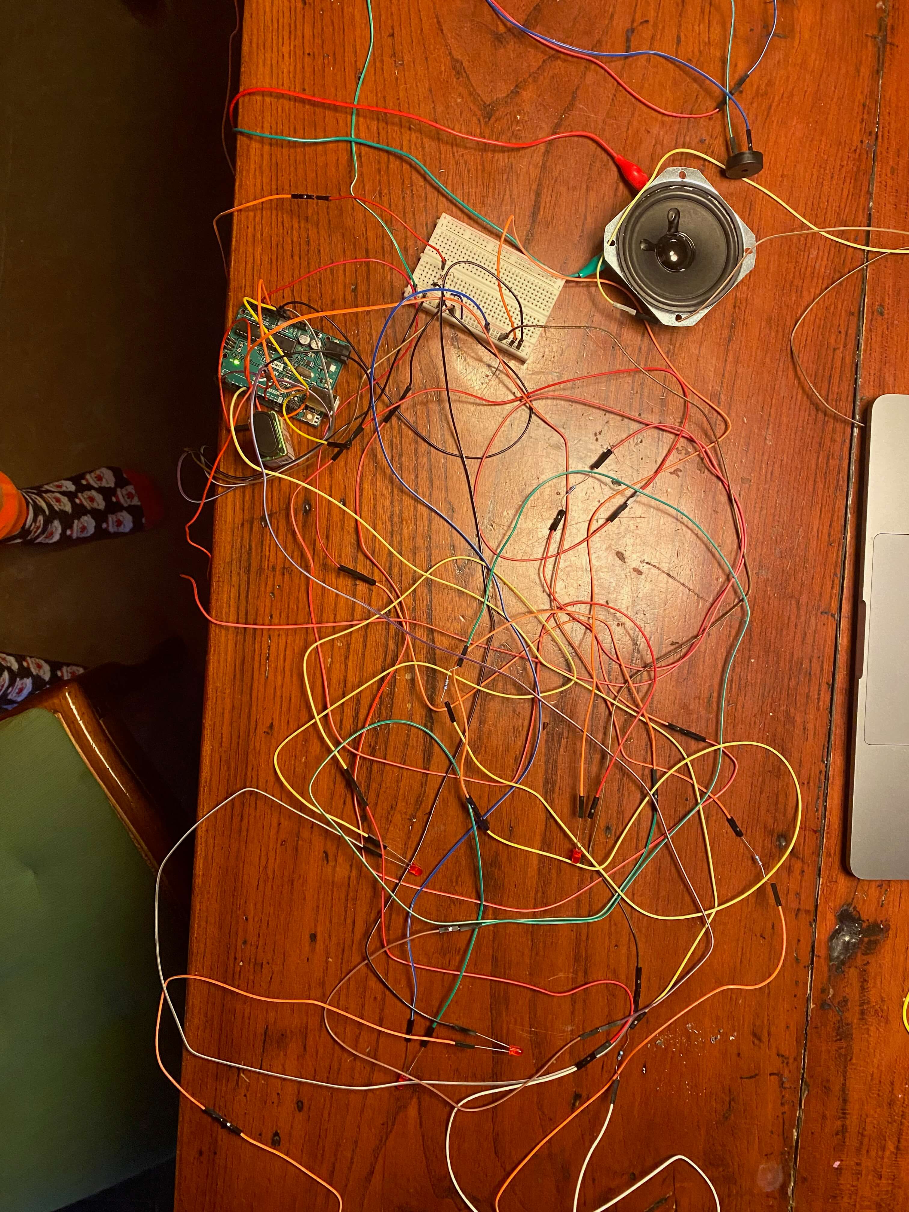
To install the warning system around my neck, I first made a necklace of several jumper cables, and tied the speaker and Arduino Uno board with cables to it. Then I hang the rest of the warning system loosely around my neck. The end result is definitely ugly! That's what I wanted.
Just like I had done with my hearing aids, I first tested my warning system by myself in a quiet corner.
Testing, testing
My warning system worked. I was armed for the world!
Files
The final Arduino IDE code for my warning system can be downloaded here.