5. E-textiles
This week I went back to high school physics which I have mixed feelings about but the idea of electronics and textiles is interesting.
Back to the basics
Every solid, liquid, gas, and plasma is composed of neutral or ionized units known as atoms. An atom consists of a central nucleus that contains protons (positively charged) and neutrons (neutrally charged), electrons (negativley charged) orbit around the nucleus.
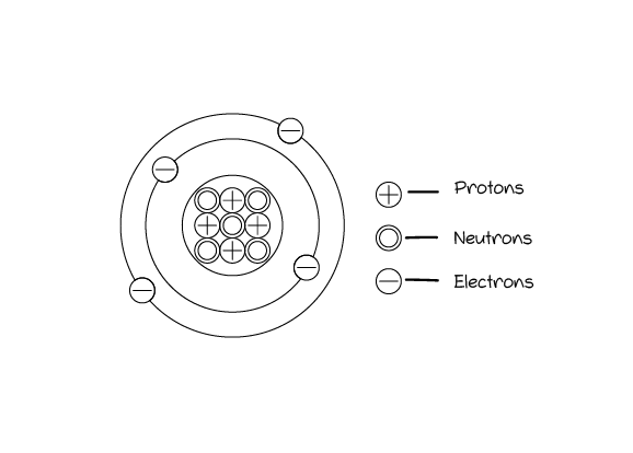
A stable atom is a neutral one, while a positive atom is the one that lost an electron, and a negativley charged atom is the one that gained a new electron.
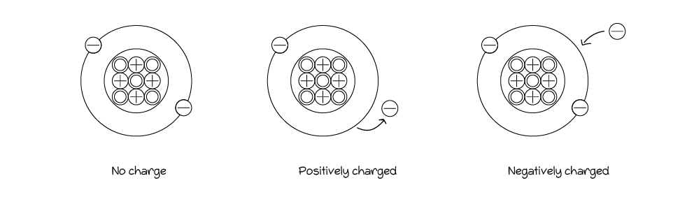
But how atoms lose or gain electrons?
A very basic concept answers: Same charge particles >> repel each other and vice versa.
When electrons move, electricity is generated.
Current: is the flow of electricity which resulted from the movement of the electrons between charged particles/atoms.
Current is measured with Ampere (Amps or A).
But how to move those electrons?
Power supply is a term used to describe any device that supplies electrical power e.g. batteries.
Usually power supplies are divided into two sides:
- A negativley charged side.
- A positivley charged side.
And the electrons from the positive to the negative.
Voltage is the difference in electric potential between two points, causing a charge.
Voltage is measured with Volts
Electrical Circuits
A circuit is the path that the electrons travel in, generating electrical enegry (electricity).
For a circuit to work it needs:
- To be closed.
- Materials that allow the electrons to travel (Traces).
- Power source.
Fun Fact
- electrons are lazy, they will travel in the shortest path possible and that's when shot circuits occur, so be aware.
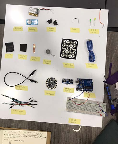
Building a circuit
With the basics revised and understood it was time to get our hands dirty and start building circuits.
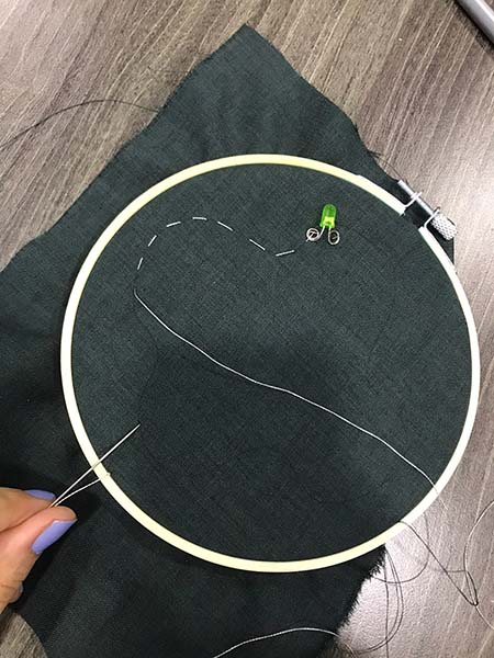
To up the game a little bit, instead of making a surface on a paper with copper tape and traces, we decided to sew the circuit on fabric, which was a good idea because my sewing skills needed all the help they could get.
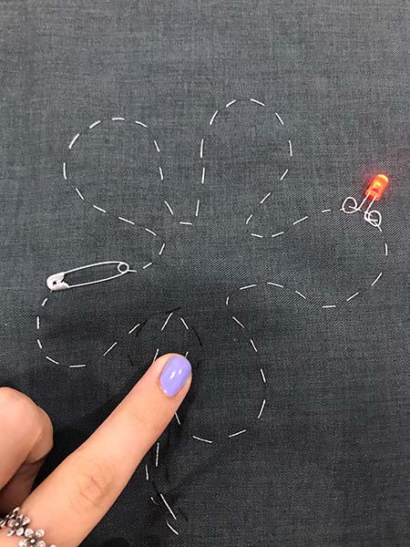
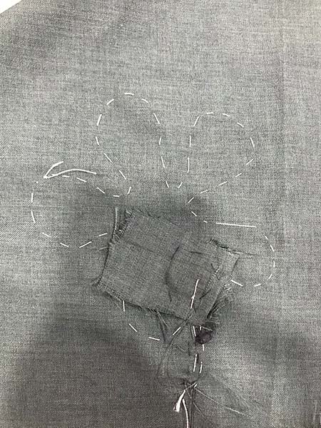
I tried again. I wanted to hide the battery behind the fabric without ruining the drawing on the fabric or making it look odd. And the safety pin was supposed to open and close the circuit but because the battery's pocket wasn't as tight as it should be the circuit was always open and will only close when pressure is applied on top of the battery. In other words, the safety pin is useless in this case.
I ended up with a momentary switch rather than a toggle switch.
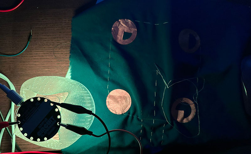
Analog Sensor
After learning the basics of Arduino and circuits I made this analog sensor that changes the led brightness according to the various resistor values coming from the various pressure values of two copper tape and a Velostat in between. The velostat acting as a resistor and the copper being conductive, each part reaching to an end, one to the positive (5V) , and the other to the negative (ground).
To test out the changing resistor values I wrote a code to print and graph the resistor values as my pressure changed.
Recap
- Digital Sensors: Has two values (on/off, 1/0, black/white) only.
- Analog Sensors: Has a range of values.
Putting it all together: A lighting fixture
For this week's assignment we are expected to create two sensors: digital and analog, they can be created separetly or in together in the same circuit.
I decided to create a lighting fixture programmed to turn on and off with a digital sensor and change colors and brightness with an analog sensor.
Let's see how's that gonna go...
First attempt with Arduino Uno
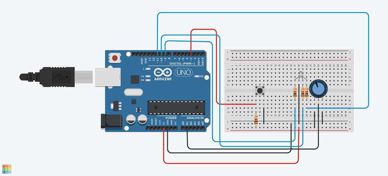
After watching tutorials and learning from example file I wrote this code that has a digital sensor that turns on the light and changes color and another analog sensor that changes brightness. I used RGB led light to change the colors without having to use more than one led light.
Coding with Arduino
const int buttonPin = 3;
const int redPin = 11;
const int greenPin = 10;
const int bluePin = 9;
int counter = 0;


void setup() {
  pinMode(buttonPin, INPUT);
  pinMode(redPin, OUTPUT);
  pinMode(greenPin, OUTPUT);
  pinMode(bluePin, OUTPUT);
  pinMode(buttonPin, INPUT_PULLUP)
}

void loop() {
  int buttonState;
  buttonState = digitalRead(buttonPin);

  if (buttonState == LOW) {
    counter++;
    delay(150);

  }

  else if (counter == 0) {
    digitalWrite(redPin, LOW);
    digitalWrite(greenPin, LOW);
    digitalWrite(bluePin, LOW);

  }

  else if (counter == 1) {
    digitalWrite(redPin, HIGH);
    digitalWrite(greenPin, LOW);
    digitalWrite(bluePin, LOW);

  }

  else if (counter == 2) {

    digitalWrite(redPin, LOW);
    digitalWrite(greenPin, HIGH);
    digitalWrite(bluePin, LOW);

  }

  else if (counter == 3) {
   digitalWrite(redPin, LOW);
   digitalWrite(greenPin, LOW);
    digitalWrite(bluePin, HIGH);

  }

  else {
    counter = 0;
  }
}
Adafruit Playground Classic
The playground is a great powerful tool but it's not the easiest to work with in Arduino (or at least that was the case for me).
Many fails and online tutorials later I managed to write an Arduino code that programs the playground to turn on an off, change colors and brightness.
Here's the result:
And here's the code:
...
 #include <Adafruit_CircuitPlayground.h>
 #include <Adafruit_Circuit_Playground.h>
 int colorCounter = 0;
 int brightnessCounter = 0;
 int oldTimeStamp = 0;


 void setup() {
 CircuitPlayground.begin();
 Serial.begin(9600);
  }

void loop() {
if ( CircuitPlayground.slideSwitch() == false) {
CircuitPlayground.clearPixels();
  }
else {

if(colorCounter == 0){

  CircuitPlayground.setPixelColor(0, 255,   255,   255);   //This is White
  CircuitPlayground.setPixelColor(1, 255,   255,   255);
  CircuitPlayground.setPixelColor(2, 255,   255,   255);
  CircuitPlayground.setPixelColor(3, 255,   255,   255);
  CircuitPlayground.setPixelColor(4, 255,   255,   255);
  CircuitPlayground.setPixelColor(5, 255,   255,   255);
  CircuitPlayground.setPixelColor(6, 255,   255,   255);
  CircuitPlayground.setPixelColor(7, 255,   255,   255);
  CircuitPlayground.setPixelColor(8, 255,   255,   255);
  CircuitPlayground.setPixelColor(9, 255,   255,   255);
 }

else if (colorCounter == 1){

  CircuitPlayground.setPixelColor(0, 0, 0, 255);    //This is Blue
  CircuitPlayground.setPixelColor(1, 0, 0, 255);
  CircuitPlayground.setPixelColor(2, 0, 0, 255);
  CircuitPlayground.setPixelColor(3, 0, 0, 255);
  CircuitPlayground.setPixelColor(4, 0, 0, 255);
  CircuitPlayground.setPixelColor(5, 0, 0, 255);
  CircuitPlayground.setPixelColor(6, 0, 0, 255);
  CircuitPlayground.setPixelColor(7, 0, 0, 255);
  CircuitPlayground.setPixelColor(8, 0, 0, 255);
  CircuitPlayground.setPixelColor(9, 0, 0, 255);
 }
else if (colorCounter == 2){

  CircuitPlayground.setPixelColor(0, 255,   0,   0);   //This is Red
  CircuitPlayground.setPixelColor(1, 255,   0,   0);
  CircuitPlayground.setPixelColor(2, 255,   0,   0);
  CircuitPlayground.setPixelColor(3, 255,   0,   0);
  CircuitPlayground.setPixelColor(4, 255,   0,   0);
  CircuitPlayground.setPixelColor(5, 255,   0,   0);
  CircuitPlayground.setPixelColor(6, 255,   0,   0);
  CircuitPlayground.setPixelColor(7, 255,   0,   0);
  CircuitPlayground.setPixelColor(8, 255,   0,   0);
  CircuitPlayground.setPixelColor(9, 255,   0,   0);
 }


else if (colorCounter == 3){

  CircuitPlayground.setPixelColor(0, 0,   255,   0);   //This is Green
  CircuitPlayground.setPixelColor(1, 0,   255,   0);
  CircuitPlayground.setPixelColor(2, 0,   255,   0);
  CircuitPlayground.setPixelColor(3, 0,   255,   0);
  CircuitPlayground.setPixelColor(4, 0,   255,   0);
  CircuitPlayground.setPixelColor(5, 0,   255,   0);
  CircuitPlayground.setPixelColor(6, 0,   255,   0);
  CircuitPlayground.setPixelColor(7, 0,   255,   0);
  CircuitPlayground.setPixelColor(8, 0,   255,   0);
  CircuitPlayground.setPixelColor(9, 0,   255,   0);
 }

else if (colorCounter == 4){

  CircuitPlayground.setPixelColor(0, 128,   128,   0);   //This is Yellow
  CircuitPlayground.setPixelColor(1, 128,   128,   0);
  CircuitPlayground.setPixelColor(2, 128,   128,   0);
  CircuitPlayground.setPixelColor(3, 128,   128,   0);
  CircuitPlayground.setPixelColor(4, 128,   128,   0);
  CircuitPlayground.setPixelColor(5, 128,   128,   0);
  CircuitPlayground.setPixelColor(6, 128,   128,   0);
  CircuitPlayground.setPixelColor(7, 128,   128,   0);
  CircuitPlayground.setPixelColor(8, 128,   128,   0);
  CircuitPlayground.setPixelColor(9, 128,   128,   0);
 }

if (brightnessCounter == 0){
  CircuitPlayground.setBrightness(30);
 }
else if (brightnessCounter == 1){
  CircuitPlayground.setBrightness(60);
 }
else if (brightnessCounter == 2){
  CircuitPlayground.setBrightness(90);
 }
else if (brightnessCounter == 3){
  CircuitPlayground.setBrightness(150);
 }


if ( millis() - oldTimeStamp > 125 ){

  if (CircuitPlayground.rightButton() == true) {

    colorCounter ++;
    Serial.println(colorCounter);   //This is not essential, I just used it to check the results and fix the errors


    if (colorCounter > 4) {
      colorCounter= 0;

     }
  oldTimeStamp = millis();
   }
  if (CircuitPlayground.leftButton() == true) {

    brightnessCounter ++;
    Serial.println(brightnessCounter);  //This is not essential, I just used it to check the results and fix the errors

    if (brightnessCounter > 3) {
      brightnessCounter= 0;

     }

  oldTimeStamp = millis();
  }

 }
} } ...
Design
Now that I have the code ready - sorta- I need to take care of the final product's design, so I used good ol' Rhino and Grasshopper to help me achieve the task.
The idea was to capture the movement of a piece of cloth, creating this feeling of continuity and seamlessness in a feminine and genuine way.
Sculpting
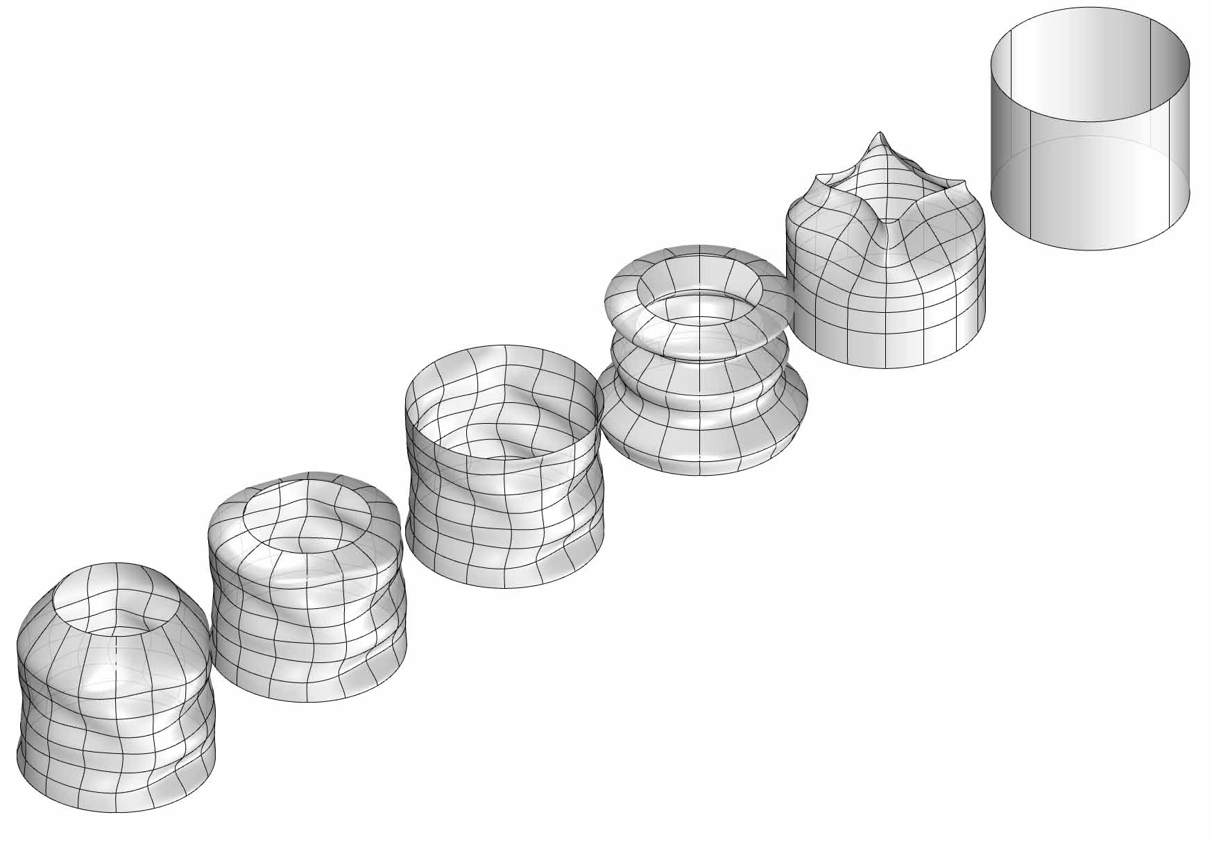
Attractors
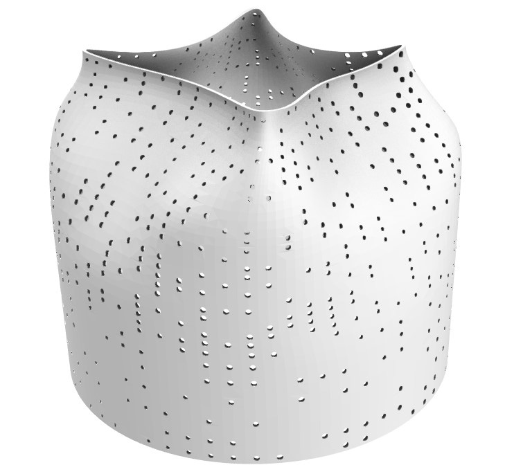
Even though I'm planning on using a transparent PLA to 3D print the lighting fixture, I needed openings still, I decided to do it with style, so I divided the surface I designed in Rhino into small panels, then I randomly split the panels and only worked on one group of them (randomly distributed). I created multiple attractor points and I measured the distances between the points and the centers of the panels (the closer the panel to the attractor point the smaller the circular opening will be and vice versa).
Here's a video of the attractor points in action.
Once I was happy with the result I got, I baked everything to Rhino, extruded Crv into solids and subtracted the openings from the surface using the Boolean Difference command. I ended up with this.
3D Printing
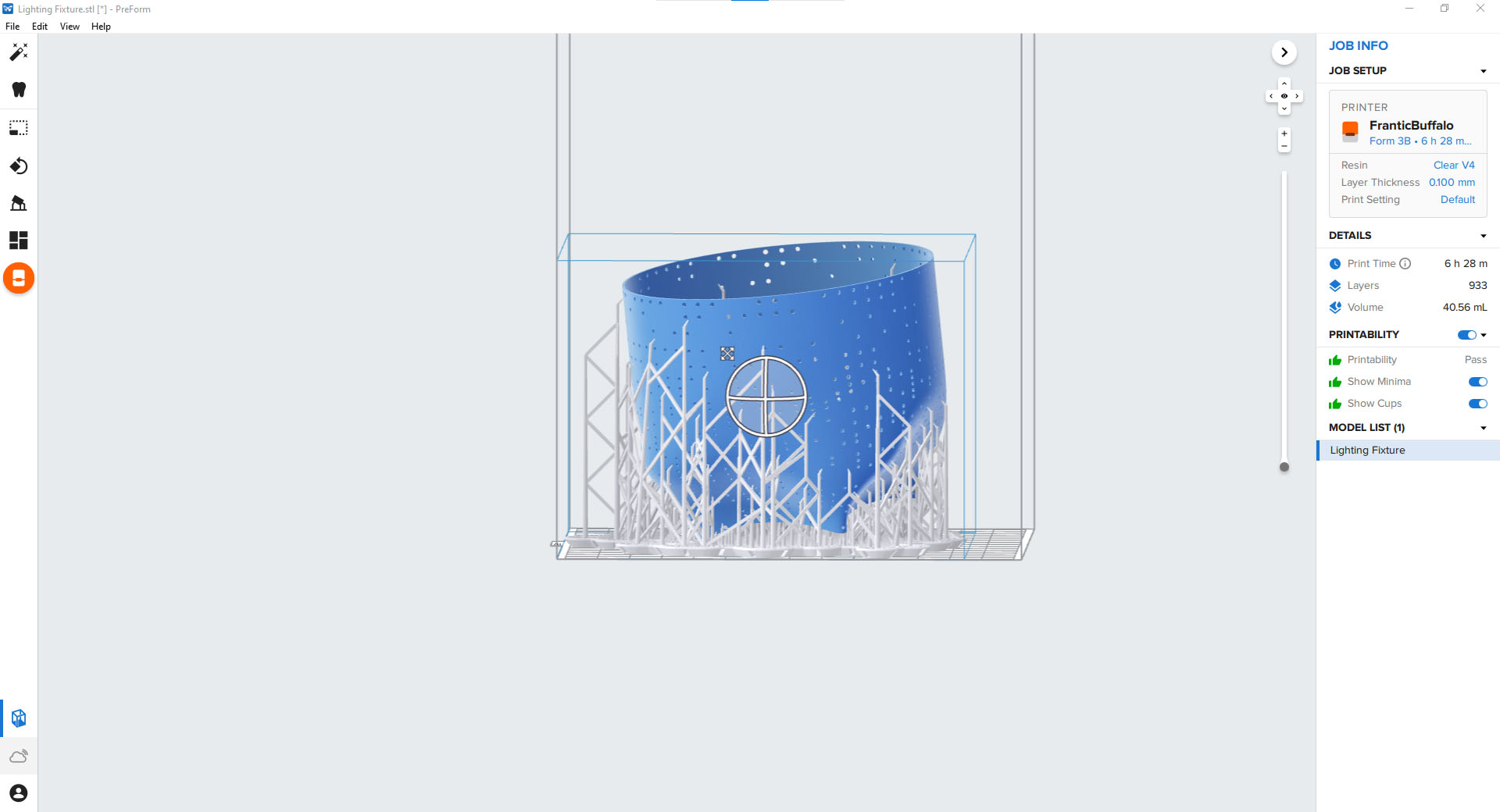
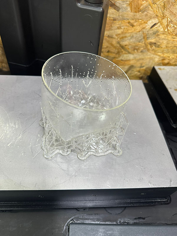
In the beginning, I was planning on printing the lighting fixture with an FDM printer using transparent filament and that's why I designed the openings to be circular, not rectangular but when it was time to print I realized that the shape would be easier to print with an SLA printer and it would take less time, so that's what I did.
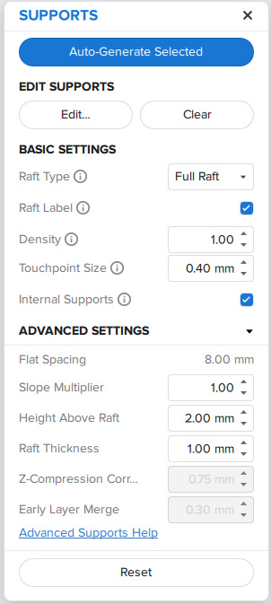
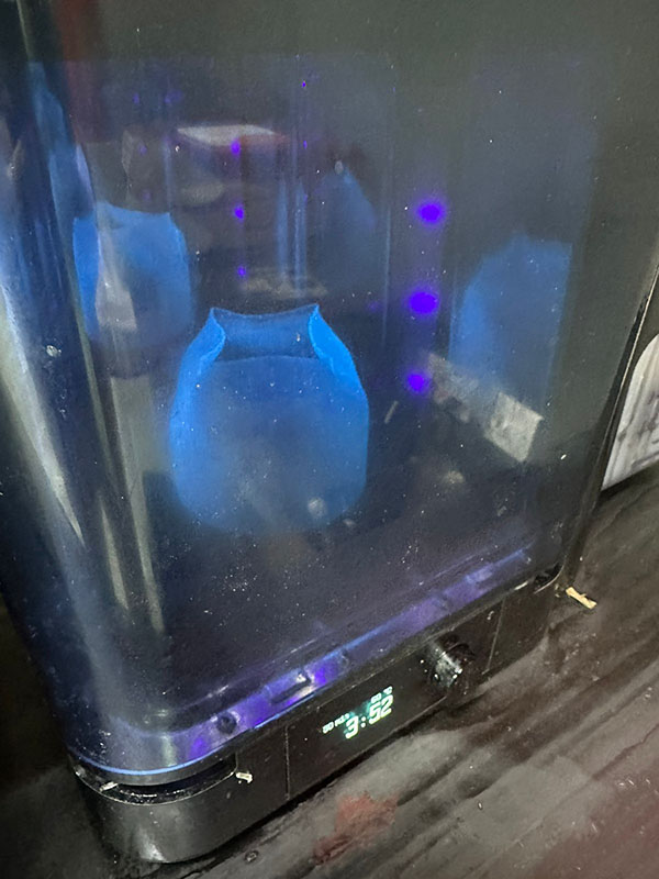
I used Formlabs 3+. After importing the stl file into the slicing software, I used the automatic supports generator and sent it for printing.
When it was ready I took out of the printer, washed it with Alcohol. Then, cured it in the curing chamber.
Analog Sensor
I decided to create a tilt potentiometer sensor. I used Kobakant's Design as a reference and a starting point.
Unlike Kobakant's Design I decided not to use resistors/Velostat between the four modes because as the current travels longer it loses power and that should be enough for my need.
Design
I designed these Sun Icons to represent the different brightness levels on Adobe Illustrator using the basic shapes (circle and filleted rectangle) then polar arrayed the rectangles around the circle.
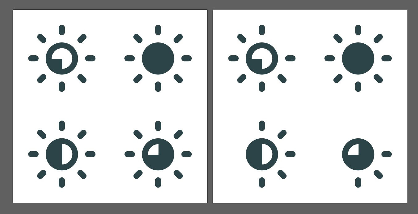
Here's an Adobe Illustrator crash course
After I choose one of these design options I will laser cut copper fabric.
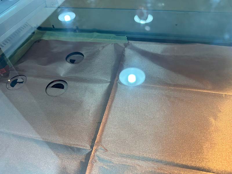
Laser Cutting
I exported the design from Adobe Illustrator as DXF and then import it to Rhino and send it for printing on the Trotec Speedy 400 laser cutter (more on laser cutting here).
I used Copper Fabric and pinned it with tape to the laser cutter.
After importing my file and calibrating the laser cutter, I started the laser cutter, it only took a few seconds.
Making the Swatch
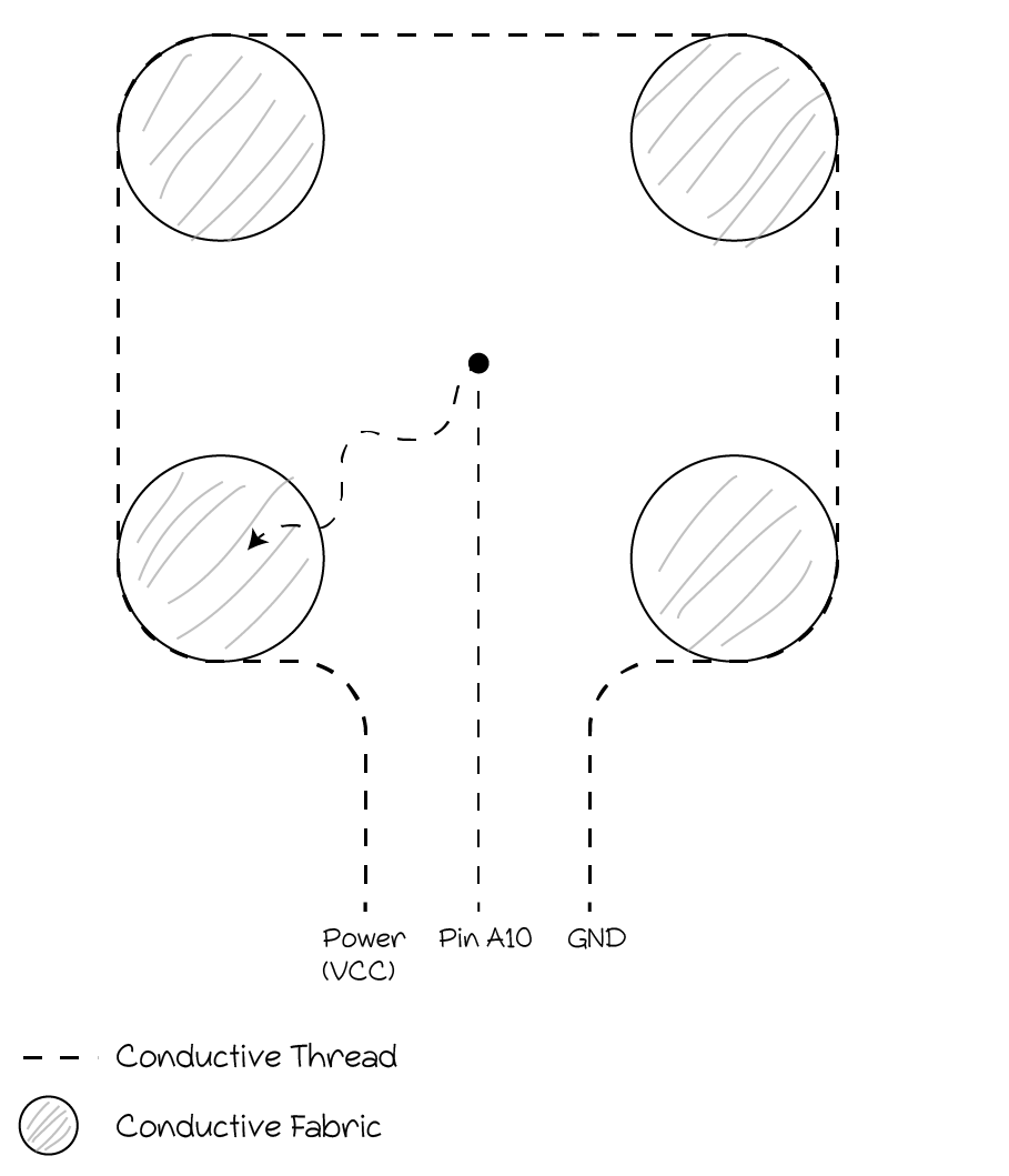
I glued the copper fabric designs on the cotton fabric with B6000 Jewelry Glue Clear Rhinestone. Then, I connected the four modes together with conductive thread that was connected from one end to the power source (VCC) and from other end to the negative (GND). And in the middle there was a line of conductive thread that was connected to an analog pin (in this case I chose A10) from one end and a conductive metal object (I didn't find something in my reach so I kept the needle I used to sew the thread) on the other end.
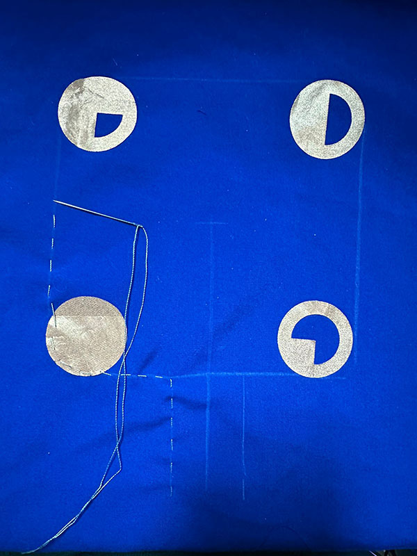
Then after connecting the thread ends to their designated spots on the Adafruit Playground Classic I'm using, I edited the code I wrote earlier so it would read analog values from pin A10.
...
#include
#define VALUE_MIN 0 #define VALUE_MAX 255
int colorCounter = 0; int brightnessCounter = 0; int oldTimeStamp = 0; uint16_t value;
void setup() { CircuitPlayground.begin(); Serial.begin(9600);
}
void loop() { if ( CircuitPlayground.slideSwitch() == false) {
CircuitPlayground.clearPixels();
} else {
if(colorCounter == 0){

  CircuitPlayground.setPixelColor(0, 255,   255,   255);   //This is White
  CircuitPlayground.setPixelColor(1, 255,   255,   255);
  CircuitPlayground.setPixelColor(2, 255,   255,   255);
  CircuitPlayground.setPixelColor(3, 255,   255,   255);
  CircuitPlayground.setPixelColor(4, 255,   255,   255);
  CircuitPlayground.setPixelColor(5, 255,   255,   255);
  CircuitPlayground.setPixelColor(6, 255,   255,   255);
  CircuitPlayground.setPixelColor(7, 255,   255,   255);
  CircuitPlayground.setPixelColor(8, 255,   255,   255);
  CircuitPlayground.setPixelColor(9, 255,   255,   255);
 }

else if (colorCounter == 1){

  CircuitPlayground.setPixelColor(0, 0, 0, 255);    //This is Blue
  CircuitPlayground.setPixelColor(1, 0, 0, 255);
  CircuitPlayground.setPixelColor(2, 0, 0, 255);
  CircuitPlayground.setPixelColor(3, 0, 0, 255);
  CircuitPlayground.setPixelColor(4, 0, 0, 255);
  CircuitPlayground.setPixelColor(5, 0, 0, 255);
  CircuitPlayground.setPixelColor(6, 0, 0, 255);
  CircuitPlayground.setPixelColor(7, 0, 0, 255);
  CircuitPlayground.setPixelColor(8, 0, 0, 255);
  CircuitPlayground.setPixelColor(9, 0, 0, 255);
 }
else if (colorCounter == 2){

  CircuitPlayground.setPixelColor(0, 255,   0,   0);   //This is Red
  CircuitPlayground.setPixelColor(1, 255,   0,   0);
  CircuitPlayground.setPixelColor(2, 255,   0,   0);
  CircuitPlayground.setPixelColor(3, 255,   0,   0);
  CircuitPlayground.setPixelColor(4, 255,   0,   0);
  CircuitPlayground.setPixelColor(5, 255,   0,   0);
  CircuitPlayground.setPixelColor(6, 255,   0,   0);
  CircuitPlayground.setPixelColor(7, 255,   0,   0);
  CircuitPlayground.setPixelColor(8, 255,   0,   0);
  CircuitPlayground.setPixelColor(9, 255,   0,   0);
 }


else if (colorCounter == 3){

  CircuitPlayground.setPixelColor(0, 0,   255,   0);   //This is Green
  CircuitPlayground.setPixelColor(1, 0,   255,   0);
  CircuitPlayground.setPixelColor(2, 0,   255,   0);
  CircuitPlayground.setPixelColor(3, 0,   255,   0);
  CircuitPlayground.setPixelColor(4, 0,   255,   0);
  CircuitPlayground.setPixelColor(5, 0,   255,   0);
  CircuitPlayground.setPixelColor(6, 0,   255,   0);
  CircuitPlayground.setPixelColor(7, 0,   255,   0);
  CircuitPlayground.setPixelColor(8, 0,   255,   0);
  CircuitPlayground.setPixelColor(9, 0,   255,   0);
 }

else if (colorCounter == 4){

  CircuitPlayground.setPixelColor(0, 128,   128,   0);   //This is Yellow
  CircuitPlayground.setPixelColor(1, 128,   128,   0);
  CircuitPlayground.setPixelColor(2, 128,   128,   0);
  CircuitPlayground.setPixelColor(3, 128,   128,   0);
  CircuitPlayground.setPixelColor(4, 128,   128,   0);
  CircuitPlayground.setPixelColor(5, 128,   128,   0);
  CircuitPlayground.setPixelColor(6, 128,   128,   0);
  CircuitPlayground.setPixelColor(7, 128,   128,   0);
  CircuitPlayground.setPixelColor(8, 128,   128,   0);
  CircuitPlayground.setPixelColor(9, 128,   128,   0);
 }


value = analogRead(10);
//if(value < VALUE_MIN) value = VALUE_MIN; //else if(value > VALUE_MAX) value = VALUE_MAX;
CircuitPlayground.setBrightness(value);
Serial.println(value);

if ( millis() - oldTimeStamp > 125 ){

  if (CircuitPlayground.rightButton() == true) {

    colorCounter ++;
    Serial.println(colorCounter);


    if (colorCounter > 4) {
      colorCounter= 0;

     }
    oldTimeStamp = millis();
   }


   }

 }
}
...