2. Digital bodies
We can't see the voices we hear but what if we can see the voices we can't hear?
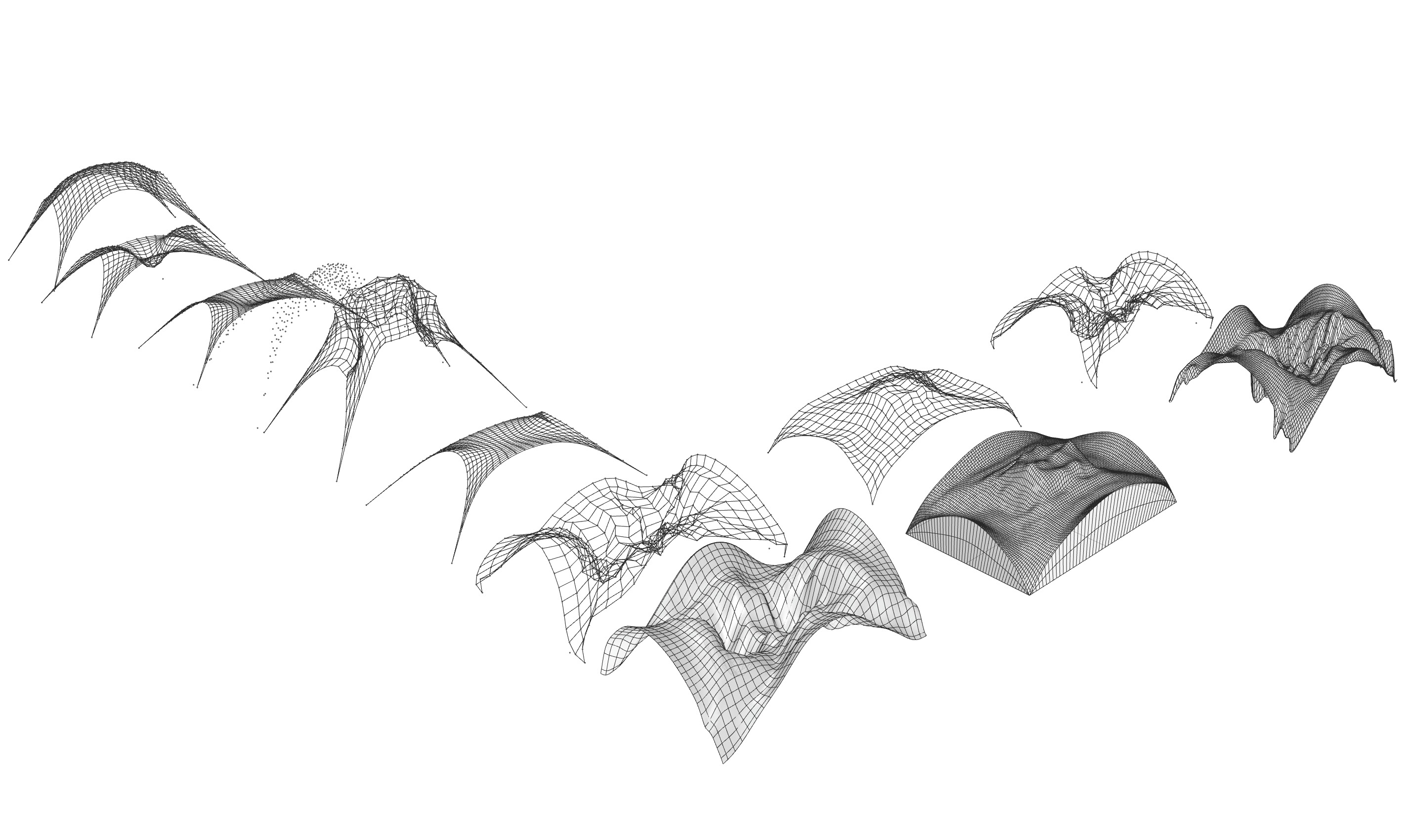
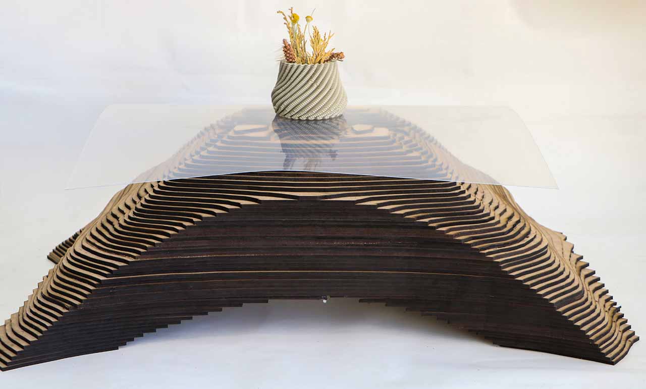
What if I told you the image below makes a beautiful music? Don't believe me, see for yourself.

Outline
This week was about researching the intersection between physical and digital bodies, how they relate, and exist within each other. Some of the techniques covered were 3D scanning and laser cutting mostly. And we were introduced to many Software such as: Make Human, Slicer for Fusion 360, rhino, sense.
Research & Ideation
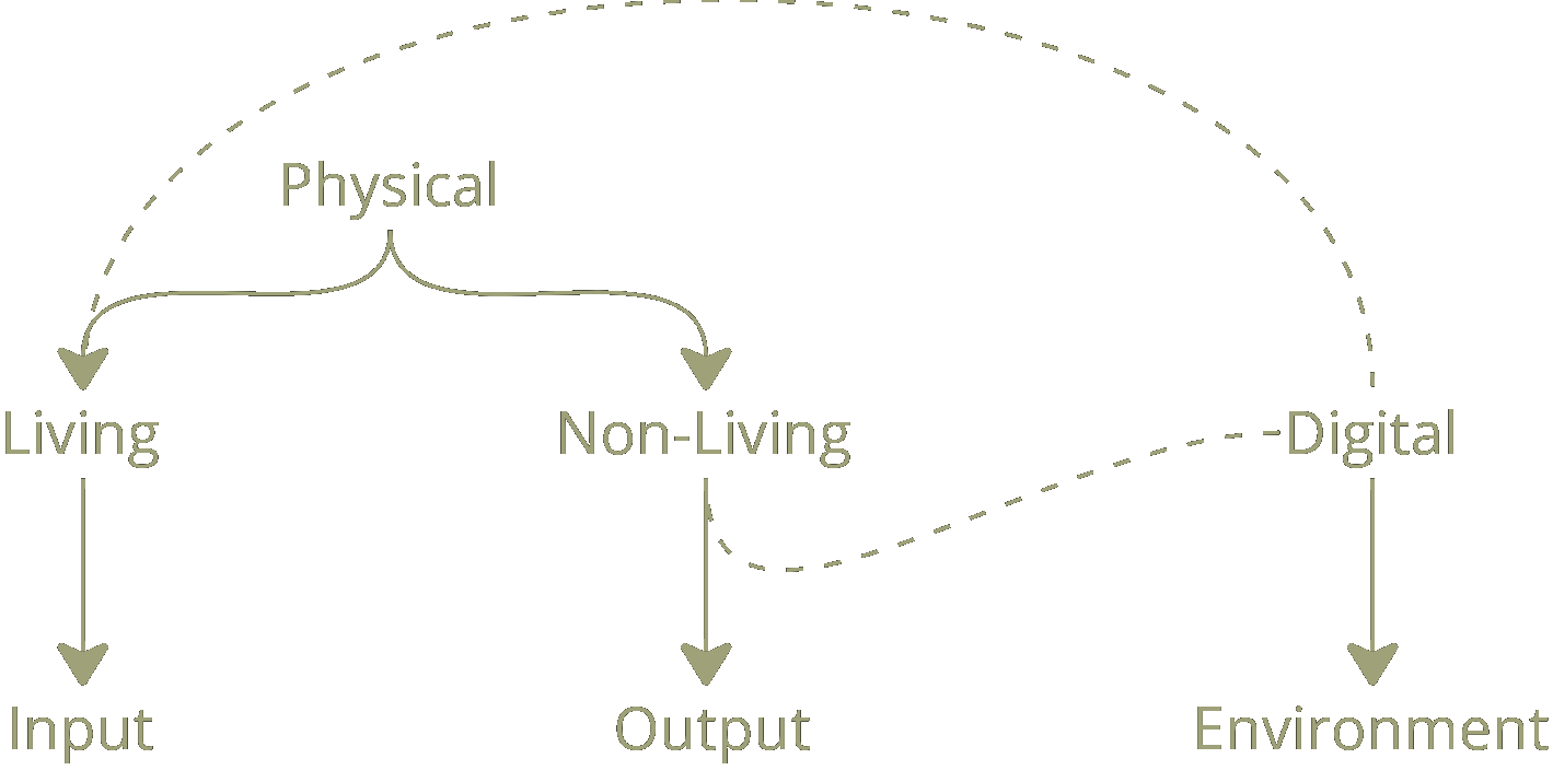
I looked into the digital bodies vs. the physical ones...with a twist. I wanted to look into the living vs. non-living vs. the digital.
The digital is the environment where all the magic happens, the living is the input and the information used to generate the non-living form.(see the picture below)
And for this assignment I decided to make a table. Lets see how will that turn out.
References & Inspiration
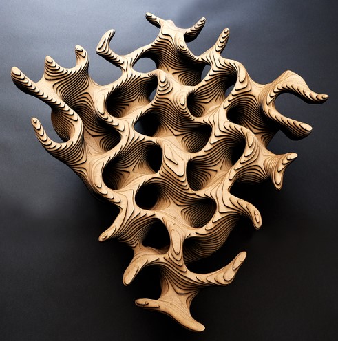
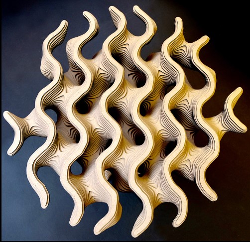
Hashem Joucka is a multi-media artist who's work relates to science and technology. Check out his official website.
Below are pictures of some of his works that inspired me, he designs data driven indoor furniture and sculpture pieces.
Process and Workflow
So I needed to find a process or an equation that exists in nature and represents a living body, I didn't want to superimpose a pattern or simply abstract a living shape into a non-living model. And that was the hardest part.
When I couldn't find an equation I could code to generate a form, I had to think of other ways to achieve my idea. So, after more brainstroming I thought I could write a script that visualizes sound and I would play sounds we hear in the nature (i.e. the sound of the desert, rain, forests, birds, water stream,...etc).
Let me show you how...
Sound Visualizer
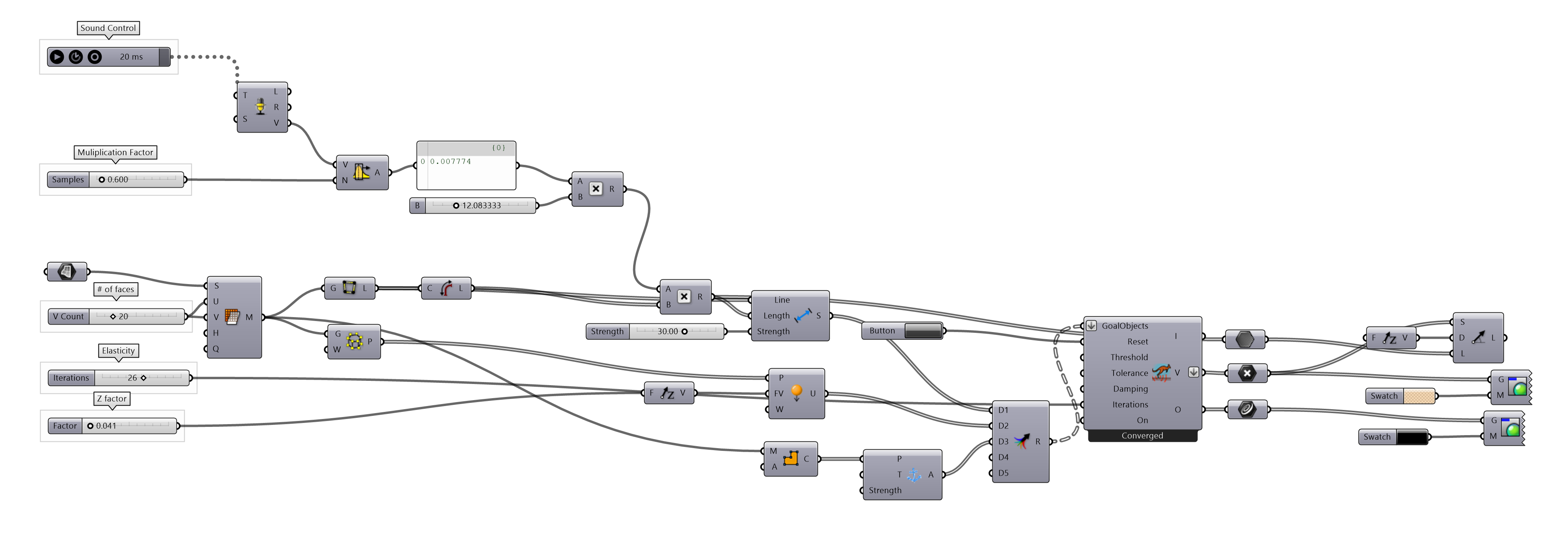
I used grasshopper (a plugin for Rhino) to build a visual script that can transform a surface and points according to the frequencies it hears.
For this grasshopper definition I used Kangaroo Physics and Firefly plugins.
Here's an image of the whole grasshopper definition and a demo of the code in action:
The music we can't hear
While my first approach was to play my Sounds we hear in nature. While researching, I stumbled upon Plant Wave. What plant wave does is that they place sensors on plant leaves and they detect the electrical variations inside the plant and graph them into frequencies which in turn plays out as a very beautiful music.
The music is different from one plant to another and it depends on several factors including the plants health (sun light and watering conditions). In other words, * Dead plants can't sing.*
Plant wave's work inspired me to visualize the sounds we can't hear but occur naturally in nature, with no human intervention whatsoever. So I played the sound of the mushroom plant for my grasshopper definition.
Iterations
Slicing
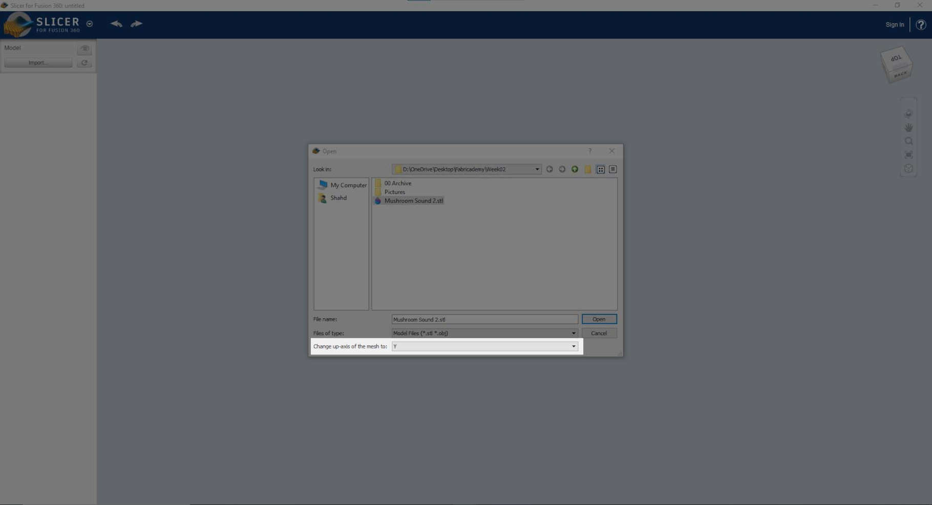
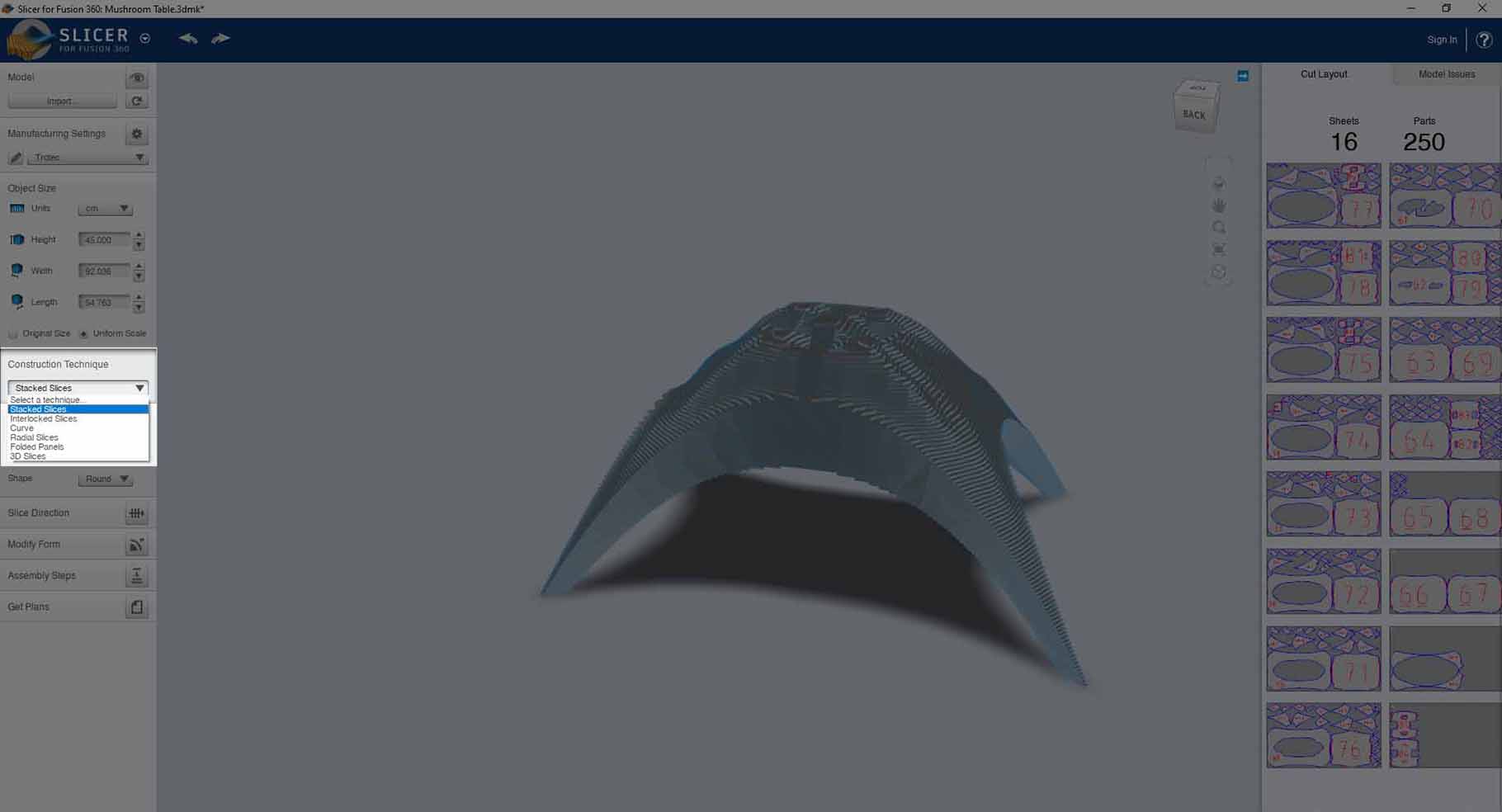
I used Slicer for Fusion 360 to get the 2D plans for my model and prepare it for laser cutting following the steps below.
- Open slicer for fusion 360 and import the .stl file.
- Change the up-axis to the Z-axis.
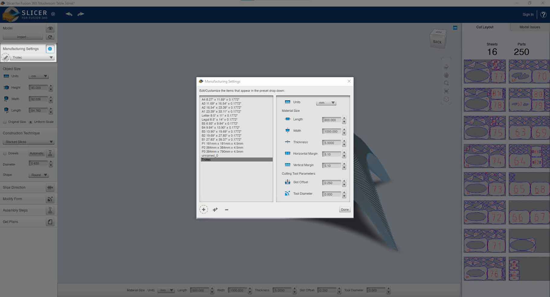
- Input the local laser cutter's settings and material thickness in the manufacturing settings.
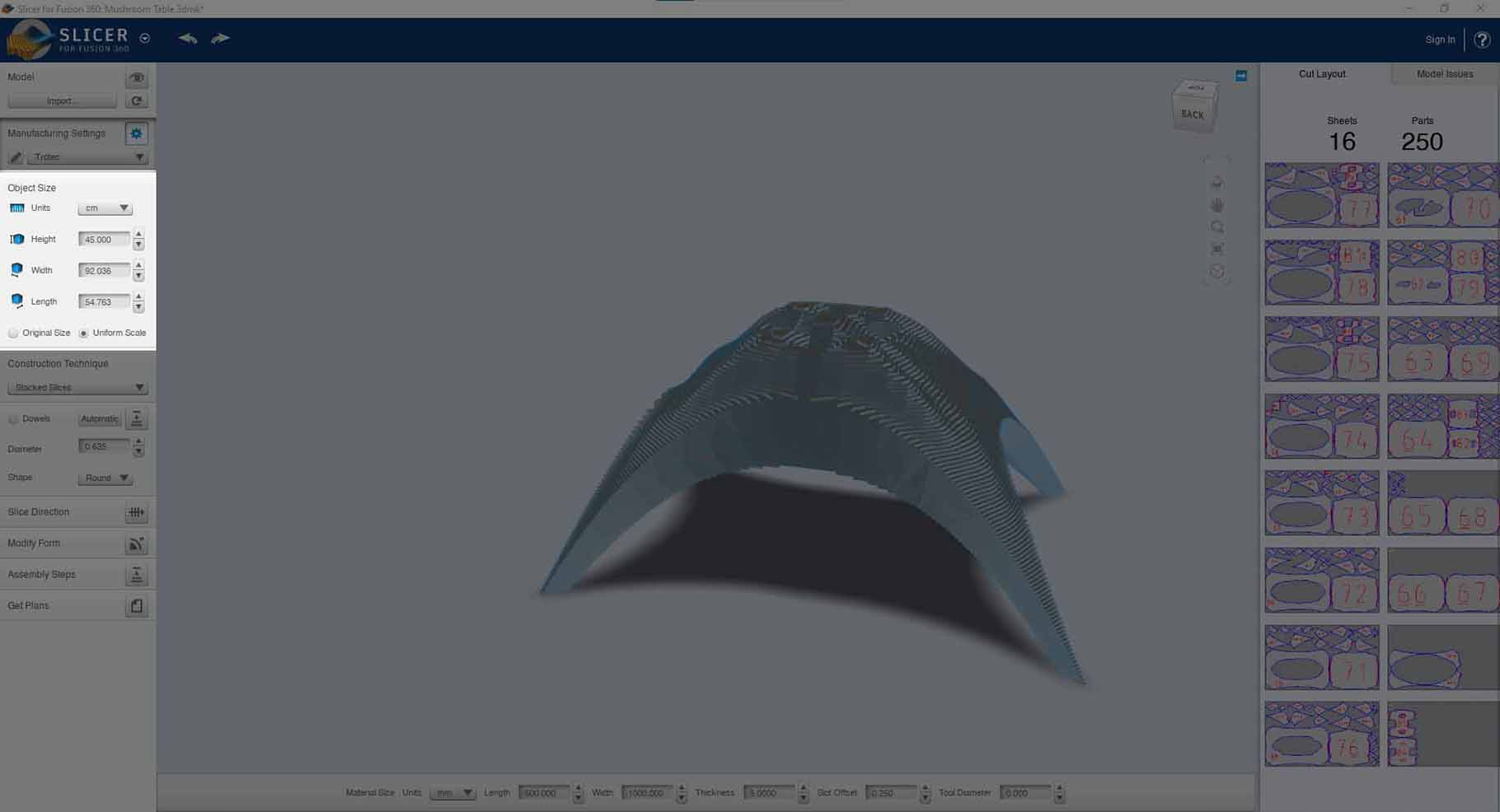
- Choose between keeping the model in it's original dimensions or changing them proportionally.
- Choose the construction method and the slice direction. (I chose the stacked slices after playing around with the other options because I felt that this one illustrates my idea more).
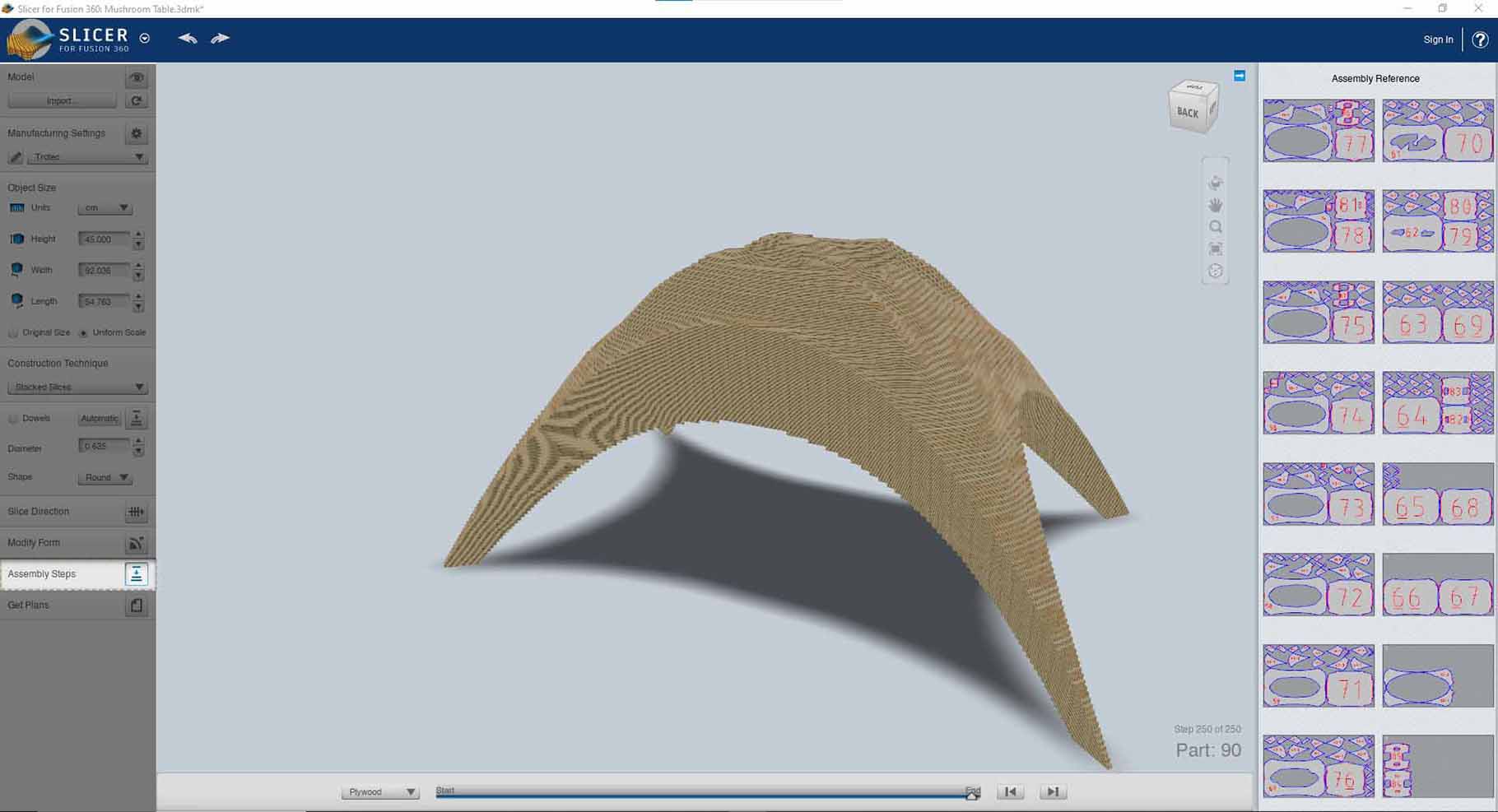
- Double check the pieces, make sure they don't clash or fail (The pieces will be marked in red if that was the case).
- You can also check the assembly steps.
- If everything is looking good, you can go ahead and export plans by clicking the get * plans * button.
- Choose the most suitable format for the 2D exports (.dxf, .eps, .pdf, ...).
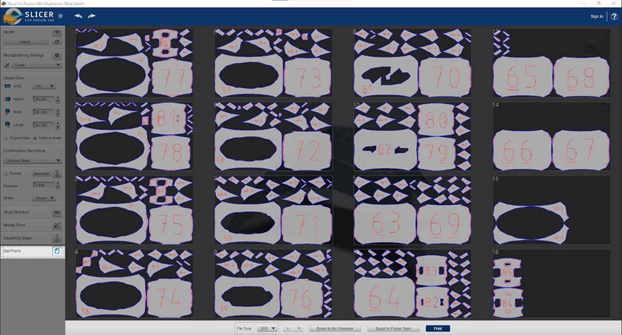
Nesting and Optimization
While the slicer does a good job creating the 2D slices for the model, the exported sheets aren't exactly optimized and nested. They need to be imported into another software and moved closer to each other, this process is called * nesting *, and it reduced the amount of materials used and the waste produced.
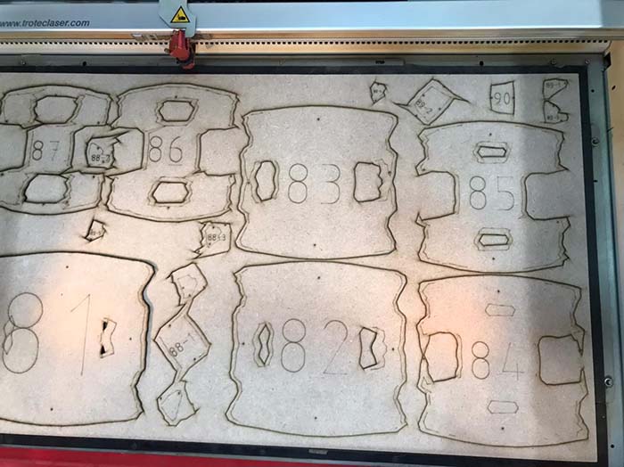
Laser Cutting
The laser cutter we have in the lab is the Trotec Speedy 400. It's pretty powerful and easy to use, here's a quick demo.
After nesting the sheets in Rhino, I opened Rhino on the computer connected to the laser cutter and started printing the sheets and choosing the laser cutter as the printer. After doing so the sheet will automatically open in the laser cutter software which was Trotec Speedy 400 in my case.
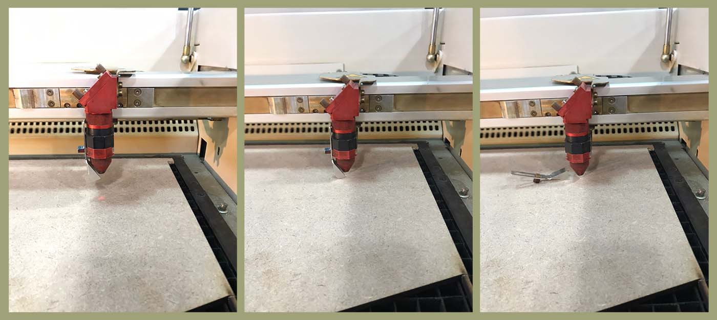
To edit the settings and cut the jobs correctly, check these bullet points out / These are things to look out for:
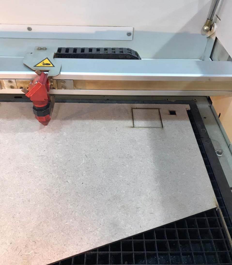
- First, you need to calibrate the laser cutter's bed, to do so you need to put your sheet on the bed and attach the calibrator to the nozzle, slowly pull the bed upwards until the calibrator drops and you have your Z-axis! (See the images below)
- Drag and drop the job imported from Rhino into the canvas.
- You can use the predefined settings or you can create your own.
- To edit and/or create new settings double click on an empty spot on the canvas.
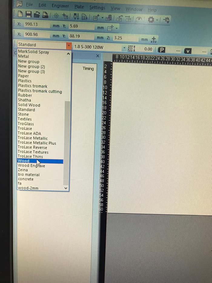
- Then choose the material preset you want to edit or add a new one from the left corner of the dialog box.
- You can manipulate the functions of the colors, the power, and speed.
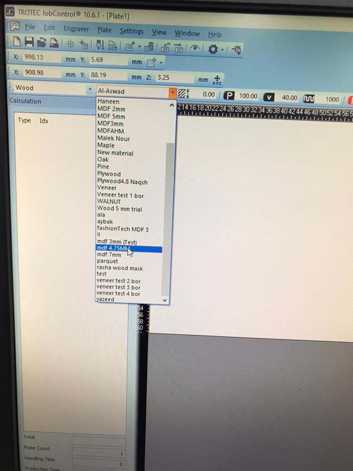
- After editing the settings, make sure to select the desired material preset from the drop down list highlighted in the image below.
- Finally, click on the job and update it to see the time expected and if it looked good you can go ahead and start the job.
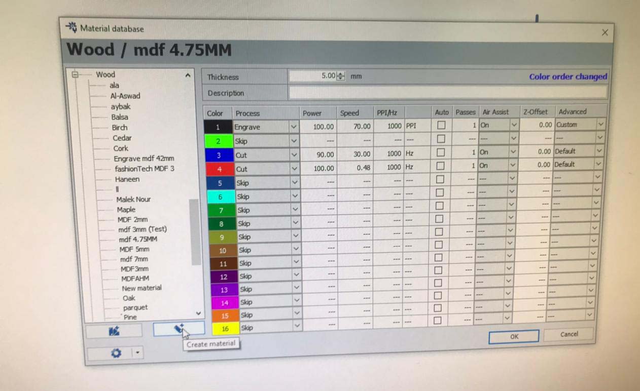
These are the laser cutter setting I ended up using for the 5mm mdf sheet:
| Color | Process | Power | Speed | PPI/Hz | Passes |
|---|---|---|---|---|---|
| Red | Cut | 100 | 0.48 | 1000 | 1 |
| Blue | Cut | 90 | 30 | 1000 | 1 |
| Black | Engrave | 100 | 70 | 1000 | 1 |
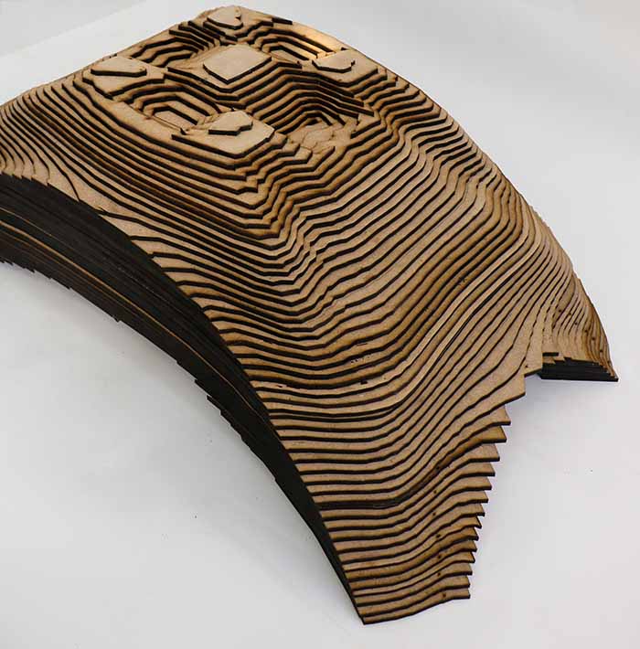
Results
Tips
-
Tryout a portion of your work, or any simple geometric shape before cutting everything, to make sure that the dimensions are correct and that the power and speed settings are appropriate.
-
Try to align the material sheet to the bed edges.
-
You can also move the nozzle to double check that your work fits inside the laser bed before turning on the job.
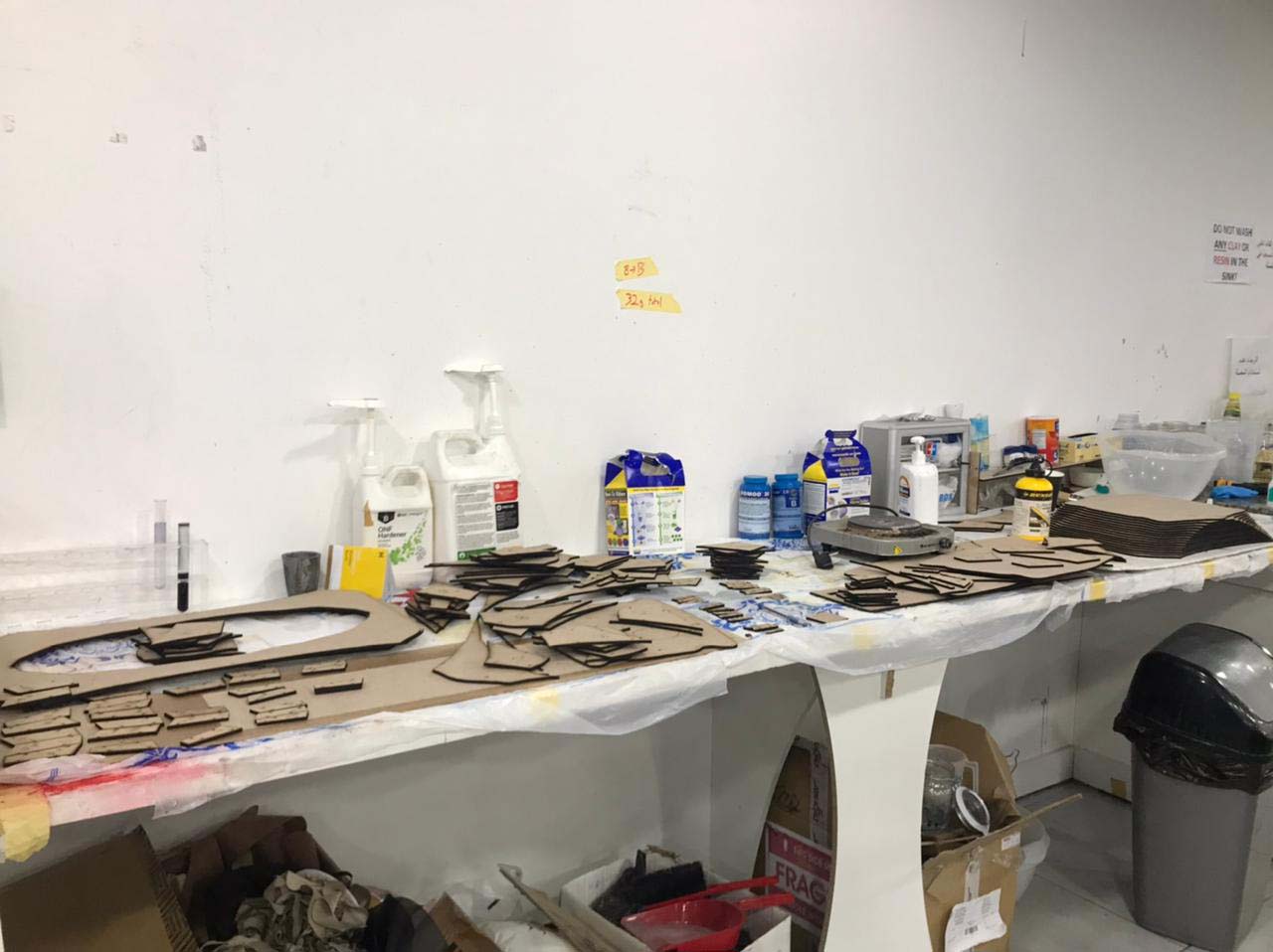
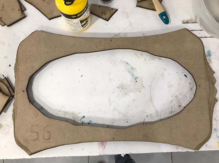
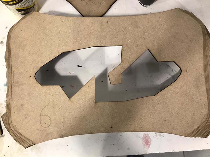
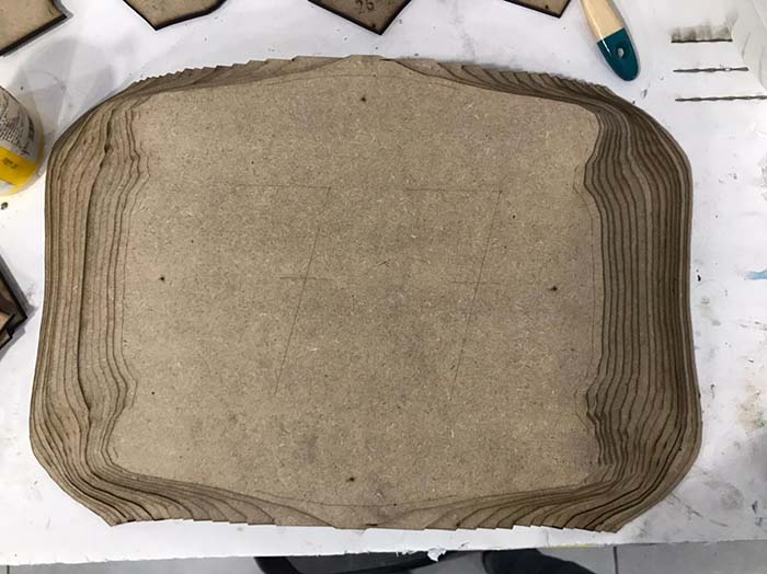
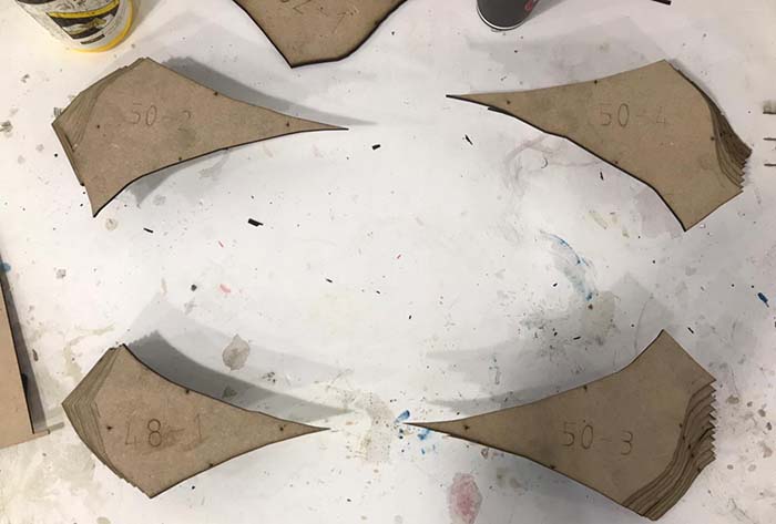
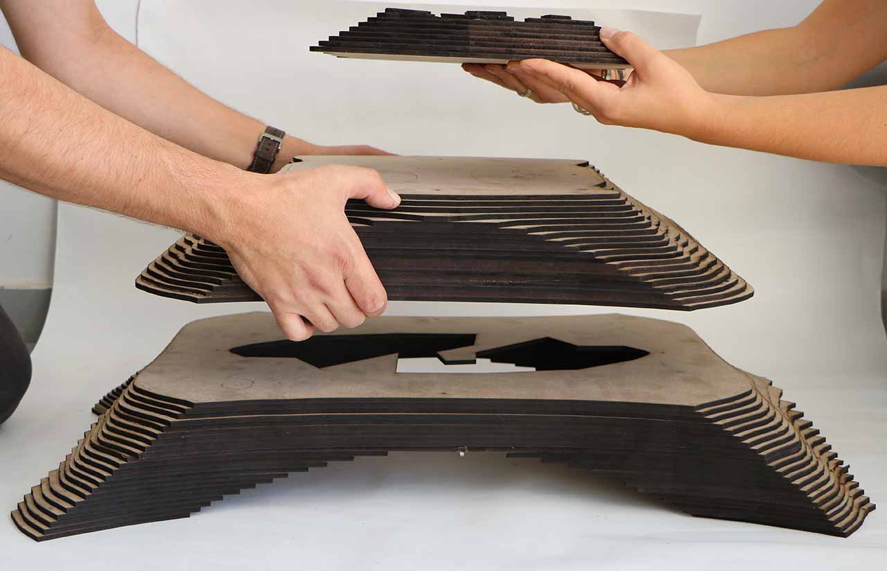
Assembly
From the laser cutter to table, sorting, gluing, and stacking.
Final Result
3D Model
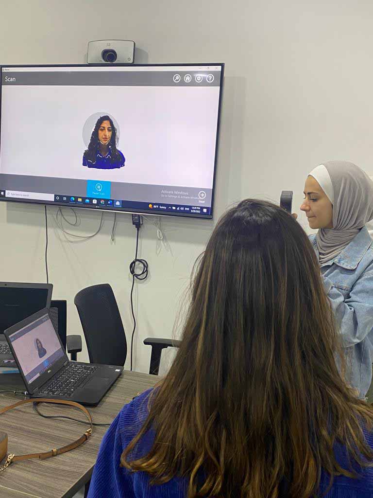
3D Scanning
This week we were introduced to different types of 3D scanners and how they operate. I worked with 2 different 3D scanners, here's a brief:
-
- Considered among the high-end scanners.
- It uses the blue light technology, catches the small details, with accuracy up to 0.05mm and resolution up to 0.1mm.
-
- Considered among the affordable scanners.
- Projects a patterned infrared (IR) beam onto the object from the bottom opening that is then detected by the middle webcam.
- Sense 1 & 2 have been discontinued.
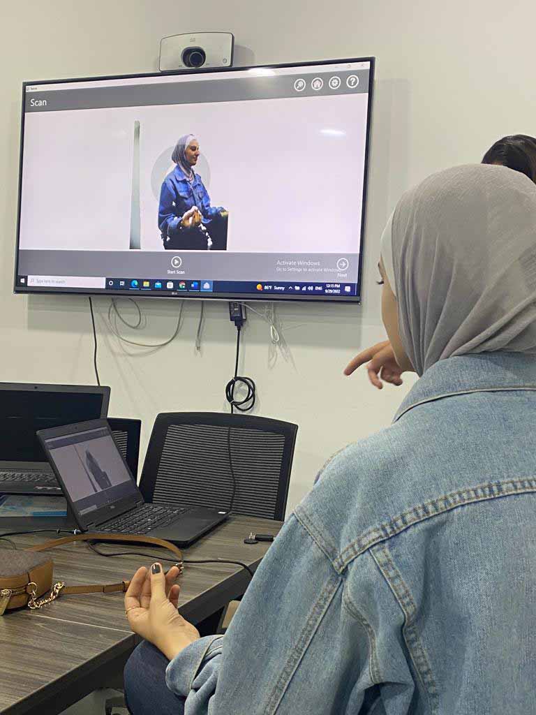
We got to try out both of them, and we scanned each other...
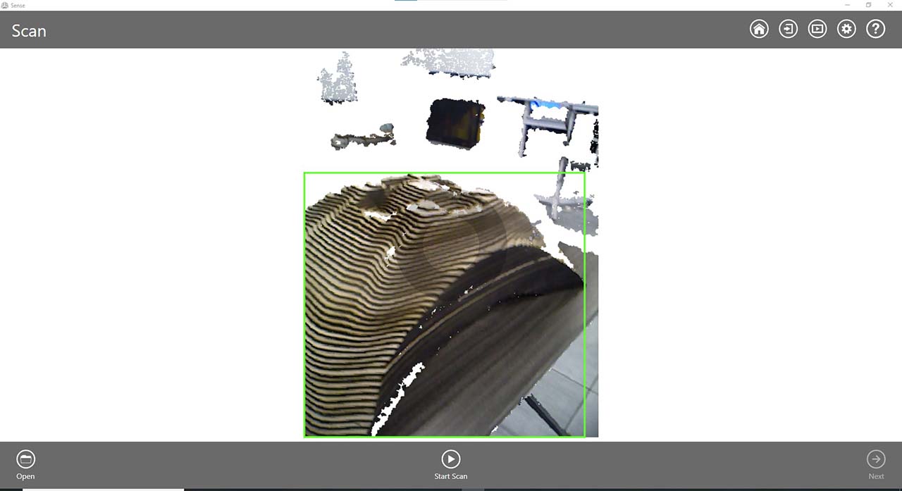
Scanning the table
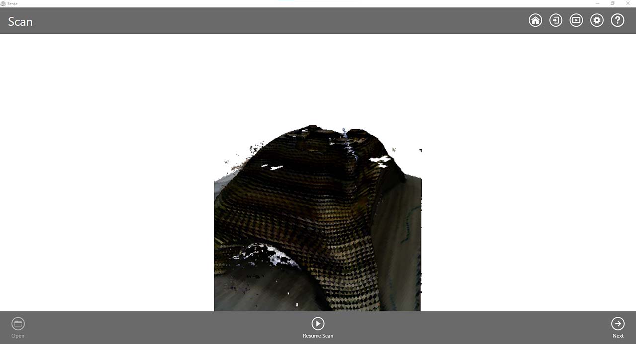
- After you download the software associated with the scanner (sense), you need to specify the size of the object you're scanning (i.e. small, medium, a person).
- Then, you need to hold the scanner at 45° away from the object and slowly rotate the object while keeping an eye on the sense software to see what spots have you missed.
- Be sure to move the scanner slowly and in a manner that makes it easier for the scanner to understand the continuation of the surfaces.
- When you're happy with the result you can pause the scanner and start retouching
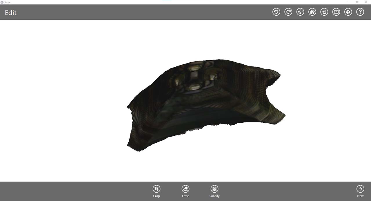
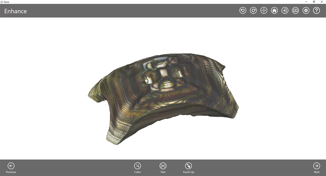
Retouching
There are some decent options for editing and retouching the 3D model after scanning, here are some:
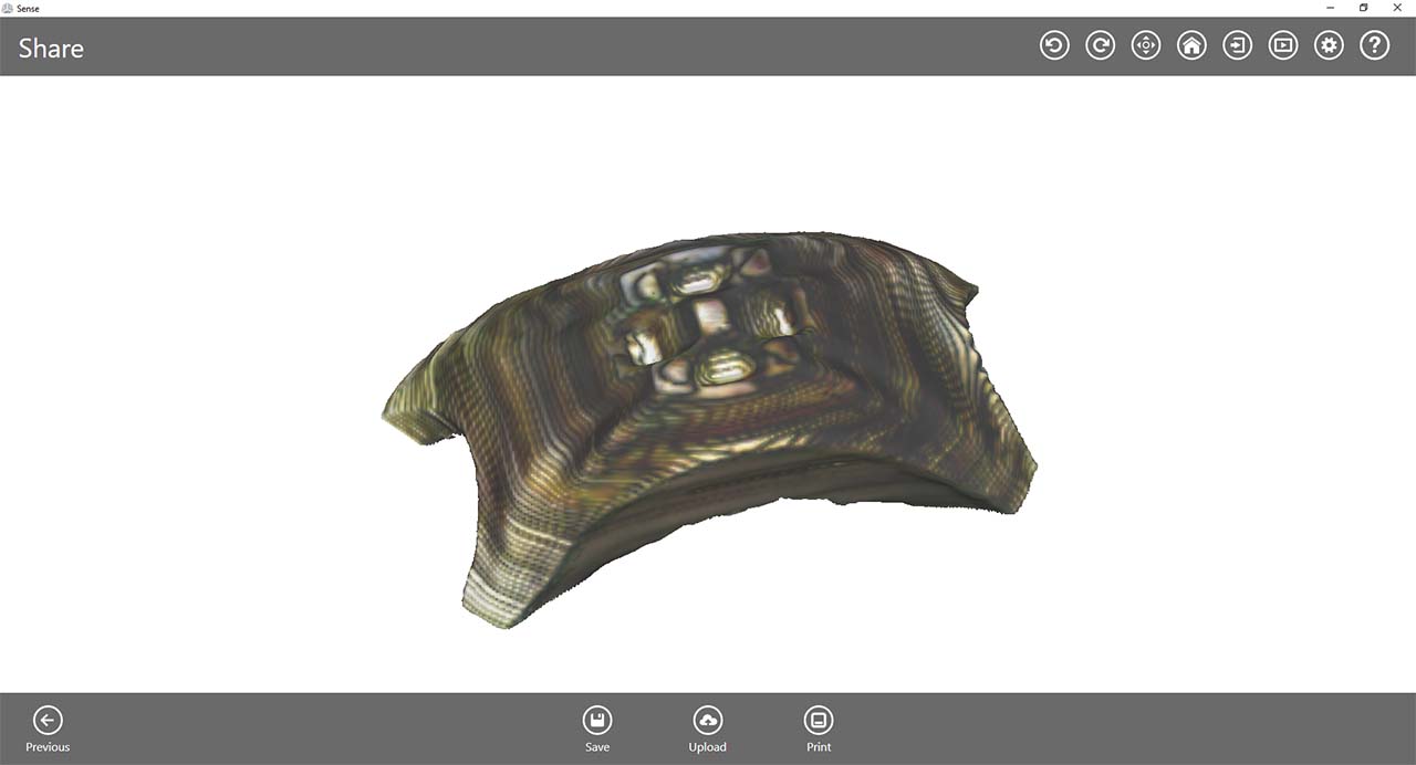
Notice that the scanner does a really good job reading the edges, colors, and depth of the model. Below is a the 3D scanned model.
Fabrication files
-
File: 3D model Rhino 7 File ↩
-
File: Laser cut sheets ↩
-
File: Grasshopper Definition ↩
-
File: Scanned Table ↩