13. Skin Electronics
In this week we looked at the intersection between tech and skin. And this was the final week in phase one (yaay).
References & Inspiration
Even though this field is relatively nouvelle, there has been a lot of good work and progress being produced by many pioneers. I;m mostly impressed by the works of Michael McAlpine and Katia Vega

Process and workflow
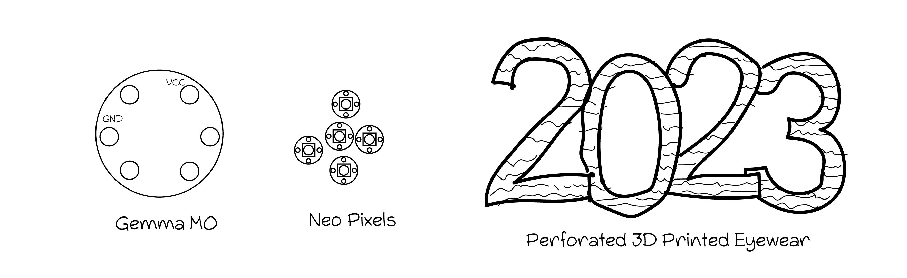
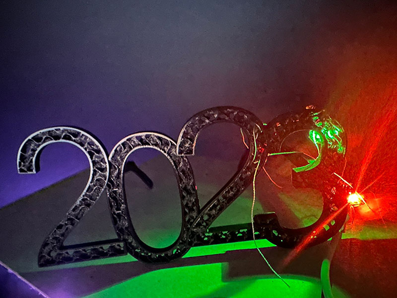
Since New Year's Eve was right around the corner I thought I'd do something that can be worn then. Something that gets us excited for 2023!
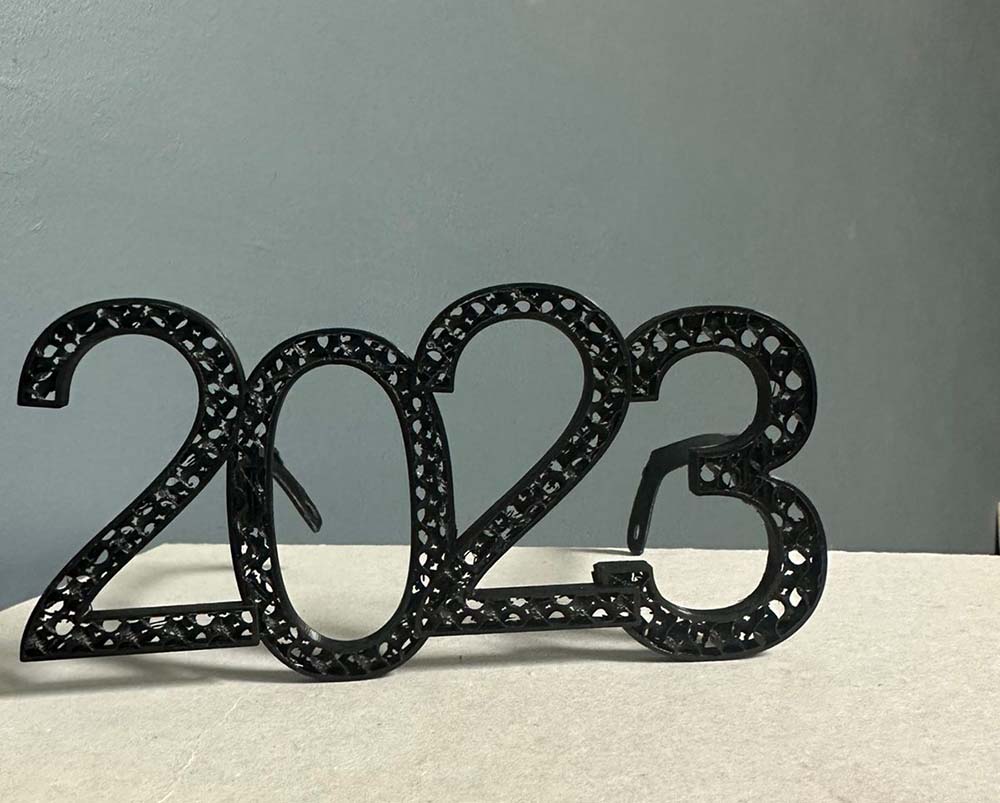
Design
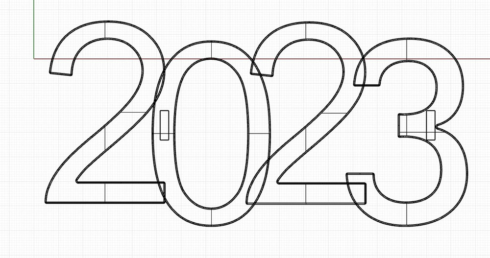
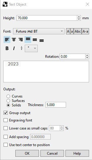
I designed this 2023 glasses in Rhino. I used TextObject command in Rhino to create solids taking the shape of a text. Then I moved each number to create an alternating effect, and I subtracted a rectangular box from both sides for the temples.
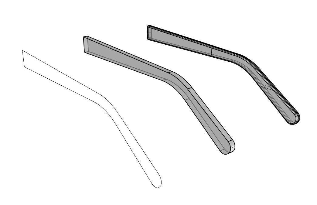
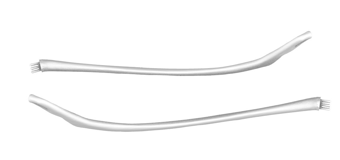
I followed this tutorial to design the temples but here's a summary of what I did:
- I traced over an image of a 2D design of the temples using the polyline command in Rhino.
- Then I filleted the edges to make it smoother with the fillet command.
- I extruded the polyline using extrudeCrv command, make sure that solid is selected.
- I filleted the solid's corners using the filletCorners command.
Then, to connect the temples inside the frame I created a box using the box command in Rhino, then mirrored it from the central axis. Finally, I subtracted the box from the frame using boolean difference command.

I created another box in the subtraction but this time I moved in to the temples and joined them together using the booleanUnion command.

Exporting
Using the export command to export Rhino geometry to different formats. In this case because I needed this for printing I exported the frame and the temples-separately- to STL files.
3D Printing
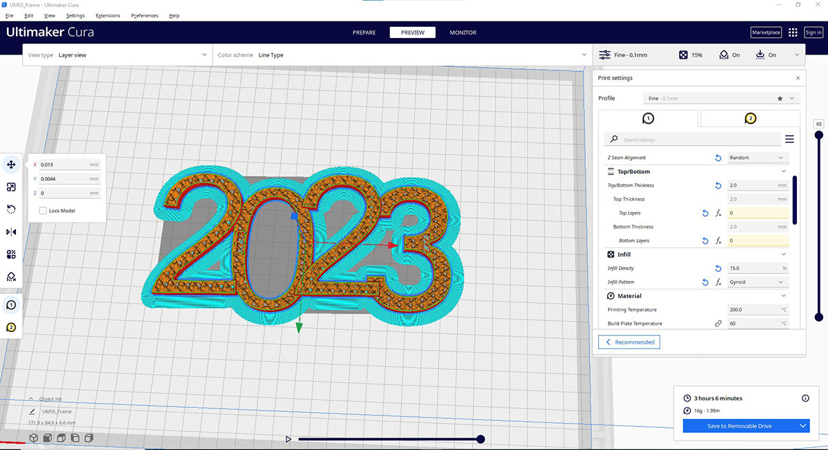
Because I plan to include lights in the glasses I needed to either design the glasses perforated or use the same printing technique I used in week07 where I printed the side walls and the infill without the top and bottom layers. I chose the later. This way the lights would come through the glasses from the spaces between the infill.
I used Ultimaker Cura we have in the lab. Here are the print settings I used for the frame:
| Material | Layer height | Infill Density | Infill Pattern | Top Layer Thickness | Bottom Layer Thickness | Build Plate Adhesion Type |
|---|---|---|---|---|---|---|
| PLA | 0.1 mm | 15% | Gyroid | 0.00 | 0.00 | Brim |
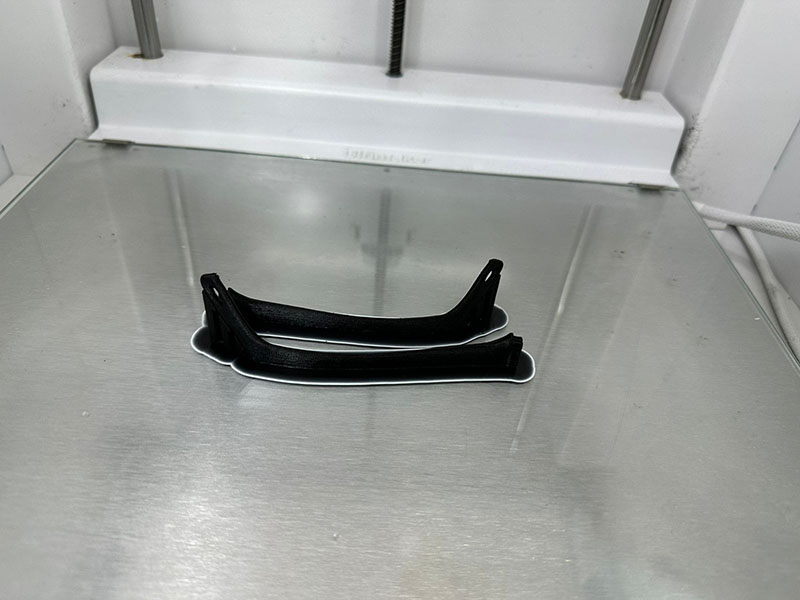
And for the temples I used:
| Material | Layer height | Infill Density | Infill Pattern | Top Layer Thickness | Bottom Layer Thickness | Build Plate Adhesion Type |
|---|---|---|---|---|---|---|
| PLA | 0.1 mm | 50% | Gyroid | 0.2 | 0.2 | Brim |
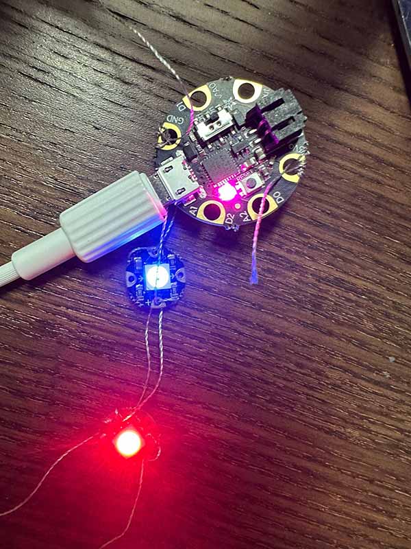
Lights On
I wanted lights that were small enough to fit on the backside of the frame and that would allow me the option to change the color and brightness so I used the Adafruit RGB Smart Neopixels flora V2 and connected them to a Adafruit Gemma M0 through conductive thread)
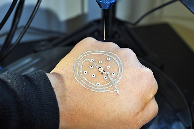
Connections
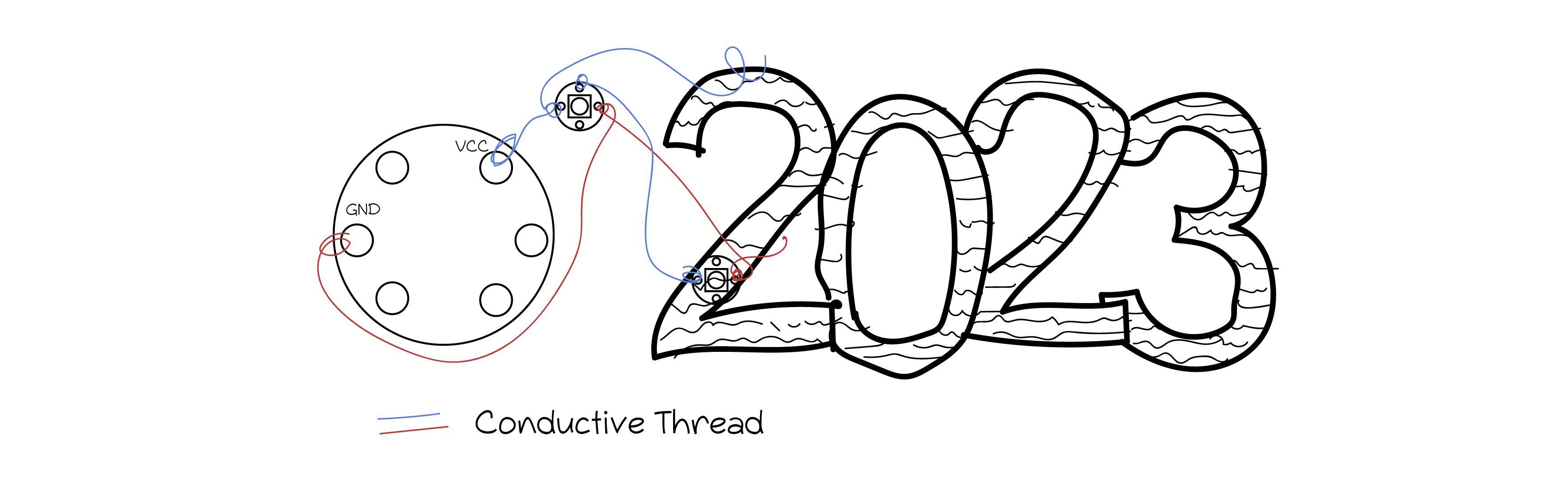
It's pretty easy to connect the neopixels to the gemma using a conductive thread. I wrapped the thread around the VCC in the Gemma board and connected it in the VCC in the neopixel #1 and then the next one and so on. I did the same thing with the GND. What's really good about adafruit's products is that it's easy to use, the VCC (+) and GND (-) are clearly marked on the board and the neopixels.
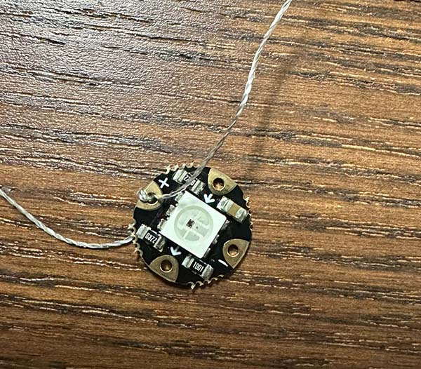
Connecting Flora
- Even though the holes are not too big in the Flora but try to wrap the conductive thread at least once.
I leveraged the infill perforations in the frame to connect the neopixels to the frame without using glue, I basically wrapped the conductive thread in the infill and back.
Mixing it up
Now that everything was set. I ran different codes in Arduino, but my favorite was this one from the example files:
// NeoPixel Ring simple sketch (c) 2013 Shae Erisson
// Released under the GPLv3 license to match the rest of the
// Adafruit NeoPixel library

#include <Adafruit_NeoPixel.h>
#ifdef __AVR__
 #include <avr/power.h> // Required for 16 MHz Adafruit Trinket
#endif

// Which pin on the Arduino is connected to the NeoPixels?
#define PIN        6 // On Trinket or Gemma, suggest changing this to 1

// How many NeoPixels are attached to the Arduino?
#define NUMPIXELS 16 // Popular NeoPixel ring size

// When setting up the NeoPixel library, we tell it how many pixels,
// and which pin to use to send signals. Note that for older NeoPixel
// strips you might need to change the third parameter -- see the
// strandtest example for more information on possible values.
Adafruit_NeoPixel pixels(NUMPIXELS, PIN, NEO_GRB + NEO_KHZ800);

#define DELAYVAL 500 // Time (in milliseconds) to pause between pixels

void setup() {
  // These lines are specifically to support the Adafruit Trinket 5V 16 MHz.
  // Any other board, you can remove this part (but no harm leaving it):
#if defined(__AVR_ATtiny85__) && (F_CPU == 16000000)
  clock_prescale_set(clock_div_1);
#endif
  // END of Trinket-specific code.

  pixels.begin(); // INITIALIZE NeoPixel strip object (REQUIRED)
}

void loop() {
  pixels.clear(); // Set all pixel colors to 'off'

  // The first NeoPixel in a strand is #0, second is 1, all the way up
  // to the count of pixels minus one.
  for(int i=0; i<NUMPIXELS; i++) { // For each pixel...

    // pixels.Color() takes RGB values, from 0,0,0 up to 255,255,255
    // Here we're using a moderately bright green color:
    pixels.setPixelColor(i, pixels.Color(0, 150, 0));

    pixels.show();   // Send the updated pixel colors to the hardware.

    delay(DELAYVAL); // Pause before next pass through loop
  }
}