Week 5: The beginning of E-textiles
In week 5 the mission was to get acquainted with the basics of electronics & tools. The process may seem simple but for many of us it is our first time using programmes such as this week’s Arduino.
What is electricity?
An introduction sensing with Emma:

Electricity:
Electricity is a fundamental form of energy observable in positive and negative forms that occurs naturally (as in lightning) or is produced (as in a generator) and that is expressed in terms of the movement and interaction of electrons.
Example: Electric current or power. Source: https://www.merriam-webster.com/dictionary/electricity
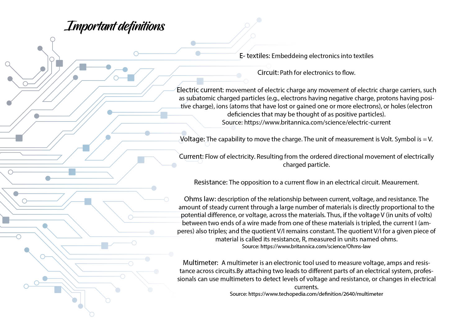
Important terms to know:
Conductive materials:
When we select a material candidate for the e-textiles we must take the following into consideration in order to make the design effective.
-
Stretchiness.
-
Solderability.
-
Thickness.
-
Resitsance.
-
Substrate and productive process.
-
Silk screen ink: analog sensor material inspo.?
Examples from De Waag and Kobrakant:
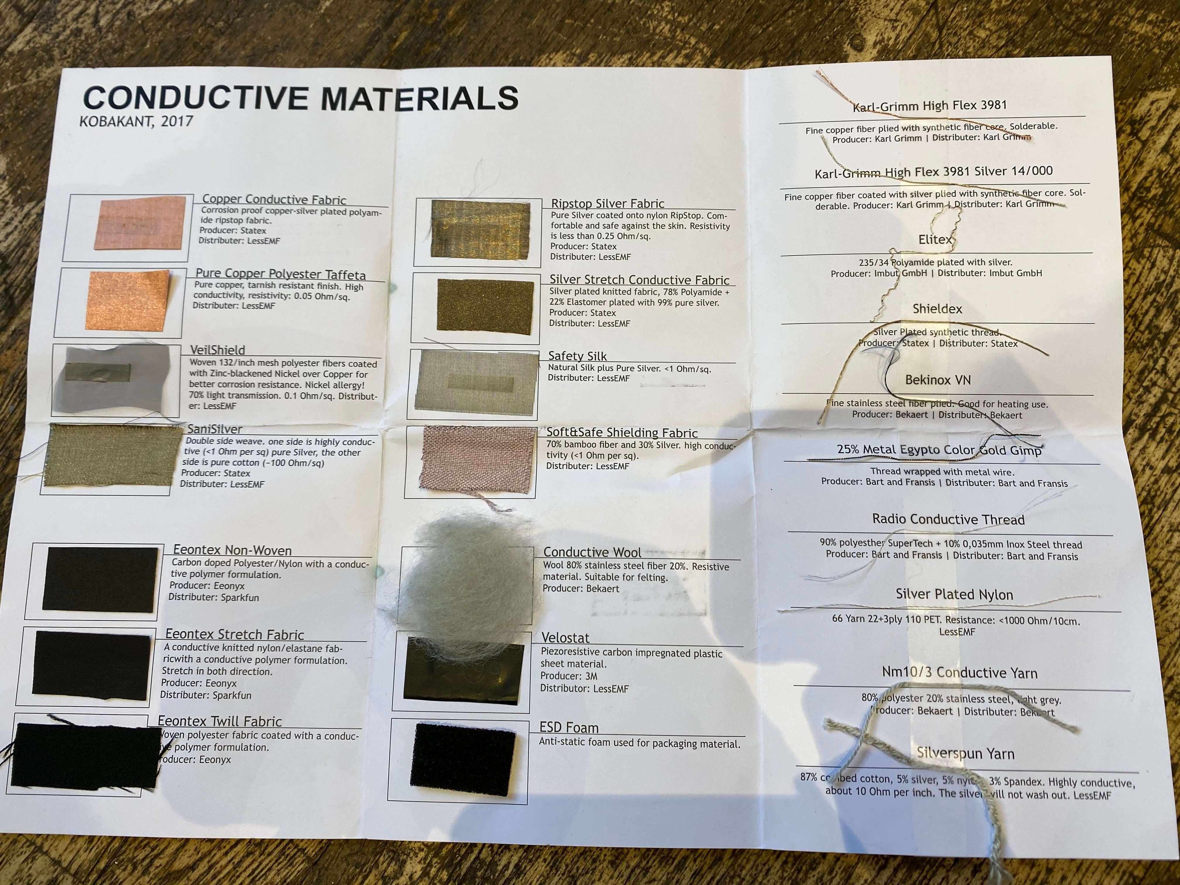
Conductive tape types and properties. Super handy if you feel like you don’t have time to measure the resistance of a material on your own! https://www.tedpella.com/adhesive_html/conductive-tapes-comparison.htm
Electronics basics:
Atoms:

The structure of an Atom is vital to know when you’re handling electricity. Also an electrical current is measure in Amperes (Amps.) The symbol for Amps. is = A. A safe number of Amps to work with is 0,005A – This is the type we were using for the LED lights in our electrical circuits.
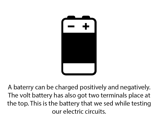
Battery 9V:
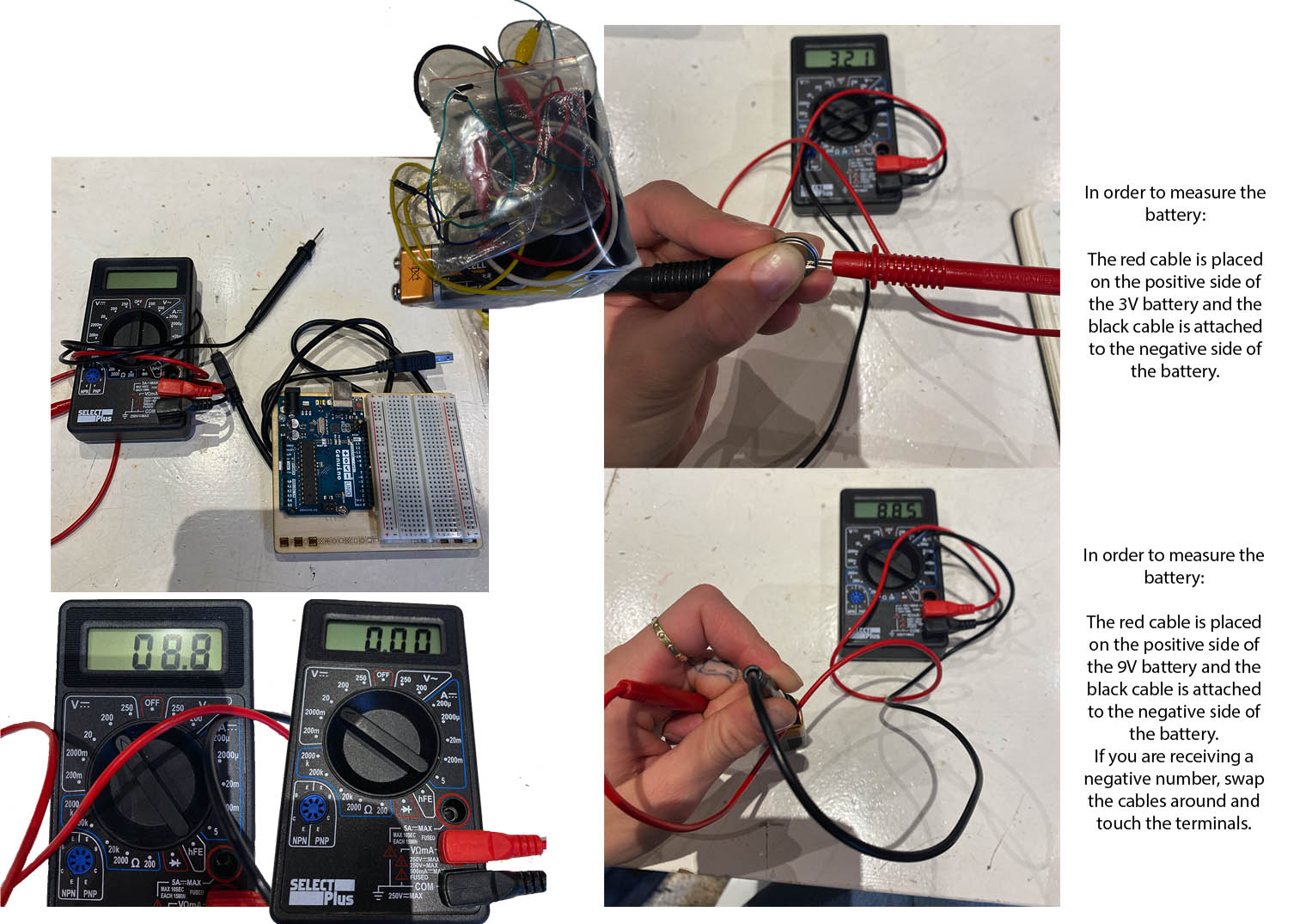
The Multimeter (Mans best friend in the electronics field):
Manual instructions: 1. Set the 2 cables (Black and red) in the right input of the multimeter.
-
- Set the knob on the right Volt. To the V with the straight line and not the wavey line.
-
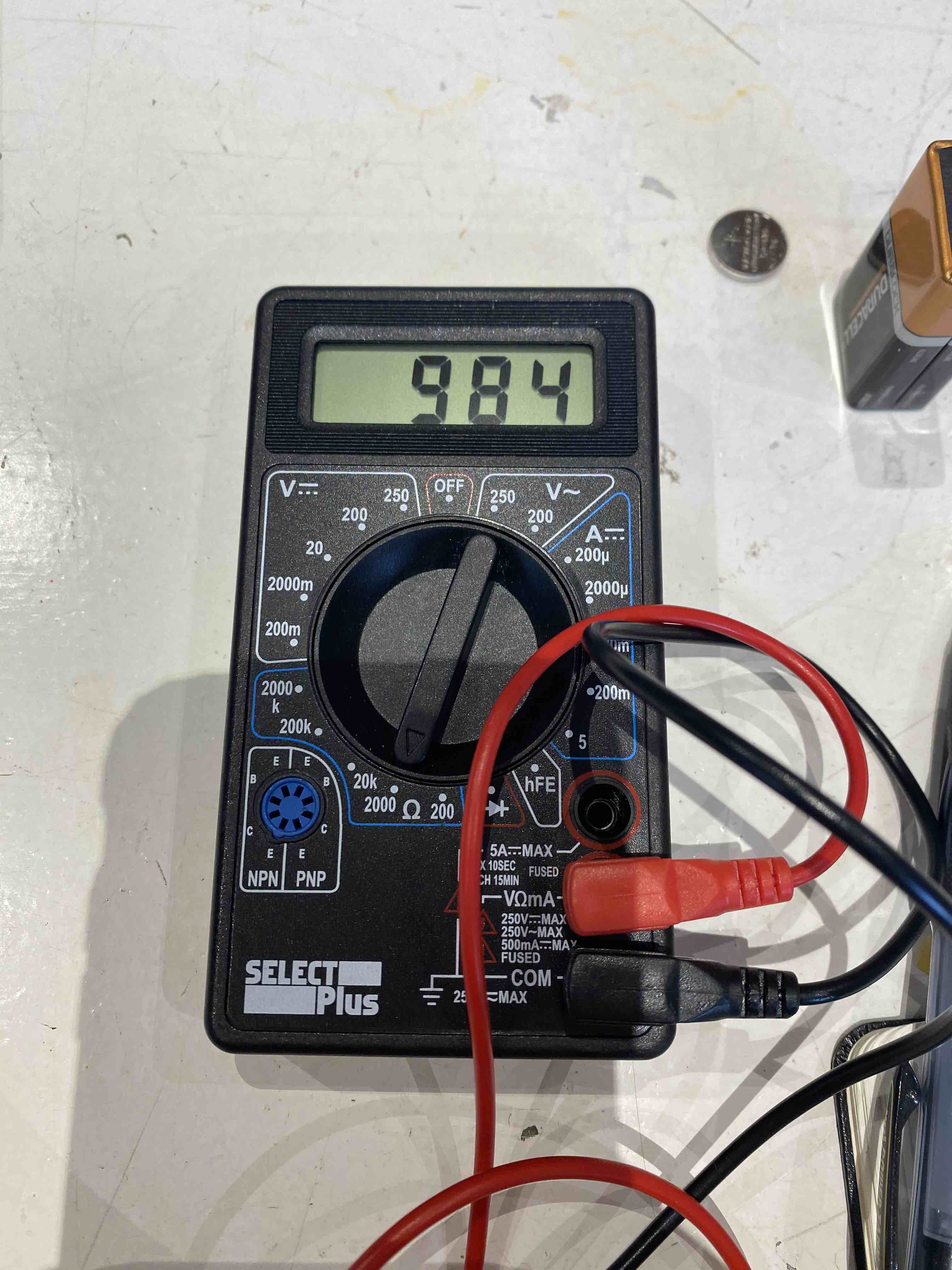
Set your meter to V-20. IF your cables have been chopped previously, use the multimeter to find our which one is the power and which one the ground.
-
Once your alligator cables are in place, use the red and black wire to determine which side to touch of the 9V battery. If you receive a – on your reading your are misplacing the cables and you must switch them around.
-
To measure a material, you must click the continuity mode for the load. When the device beeps touching your chosen material, it means that it is conductive.
Short circuit:
Electrical circuit that has been constructed in a way that a current is travelling in an unintended direction/path. There is very low or no electrical impedance. As a result, there is a more extreme current flowing through the circuit. Energy is therefore released too quickly between the two points and the circuit can overheat or even explode. This is where you find out how sometime 2 pieces are not meant to be connected.

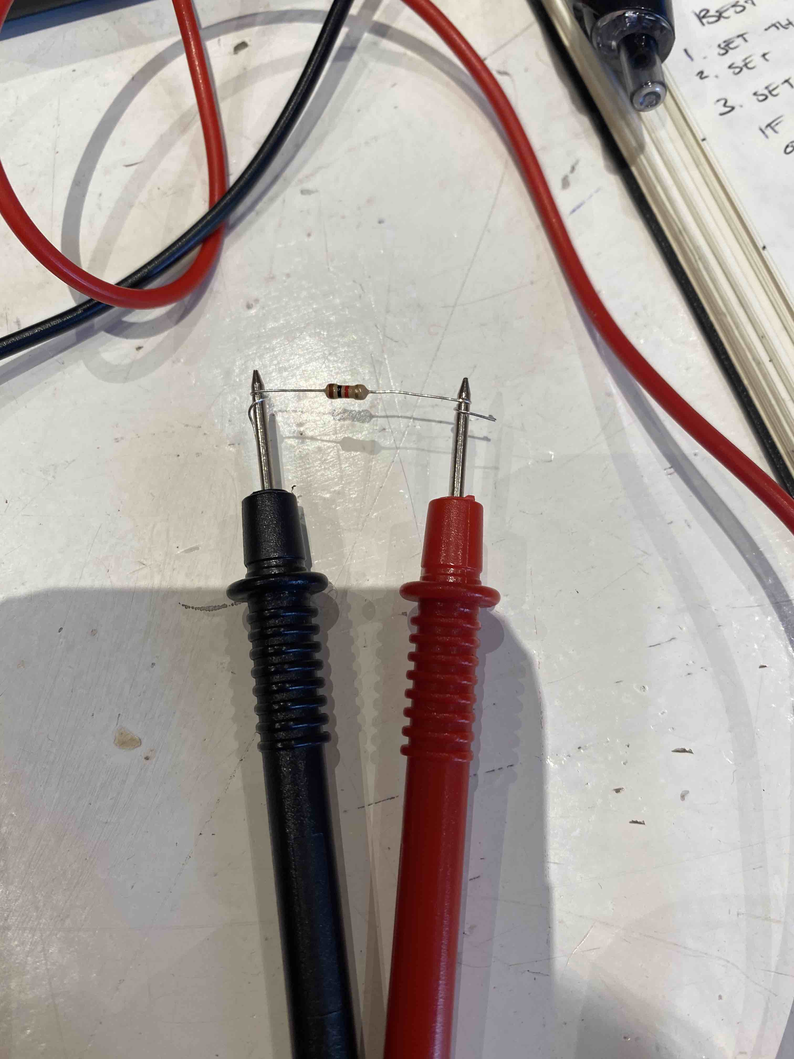
Resistor:
The purpose is to impede a flow or current and impose a voltage reduction.
The resistor has 2 sides, the orientation is not important.
For each circuit you need a different type of resistor.
The resistance in a resistor is measures in Ohms with an omega sign.
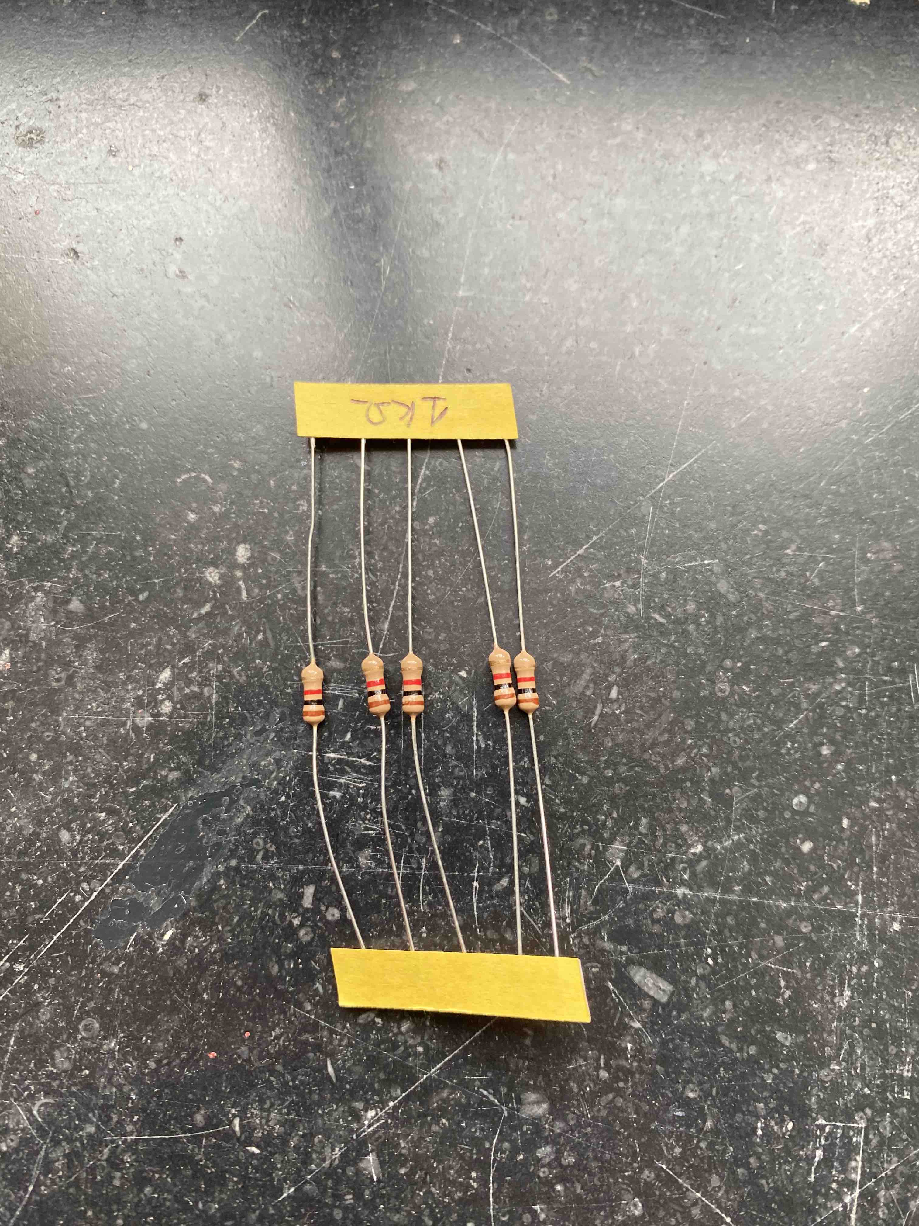
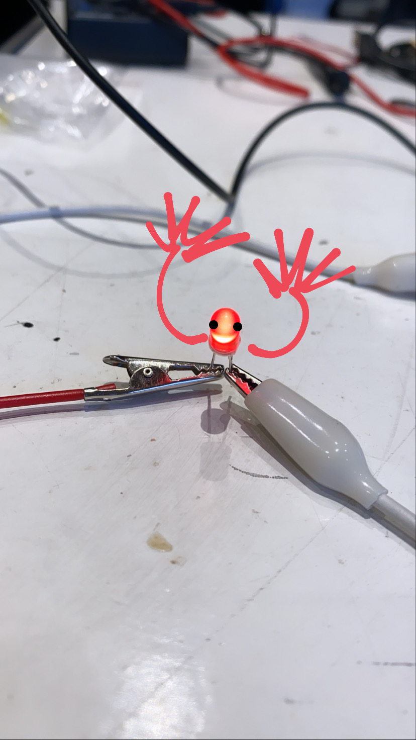
I really do think that they look like cute little dolls.
Schematic: The schematic diagram, is a representation of elements of a system using Graphic and abstract symbols.
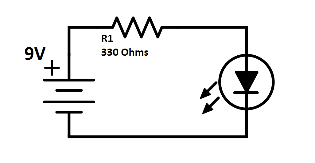
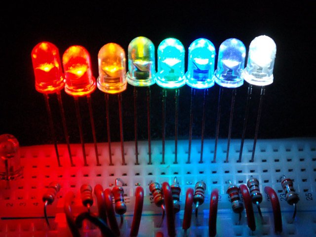
LED:
light-emitting diode: a device that produces a light, especially on electronic equipment source: https://dictionary.cambridge.org/dictionary/english/led
-
A led has two terminals.
-
2 different legs (terminals): Anode = +. Cathode = -/
-
The current only flows in one direction so the orientation is only in one direction.
-
A led has two terminals.
-
For our circuit exercise we were able to use a battery of 3V and the 9V, although we had to use a resistor seeing as the voltage was too high.
-
By suing Ohms Law and measuring the resistance of the resistor with the multimeter, we were able to find the perfect resistor for our circuit.
Soft Sensors: Digital and Analogue
-
There are only to statuses for digital.
-
For an electric signal:
o GND – VVC
o 0 – 1
o Low – High
- Switches: On/off.
How do analogue sensors work?
-
Analogue counts all values between the minimum and maximum.
-
If its an electrical system:
o Minimum: GND.
o Maximum: VCC.
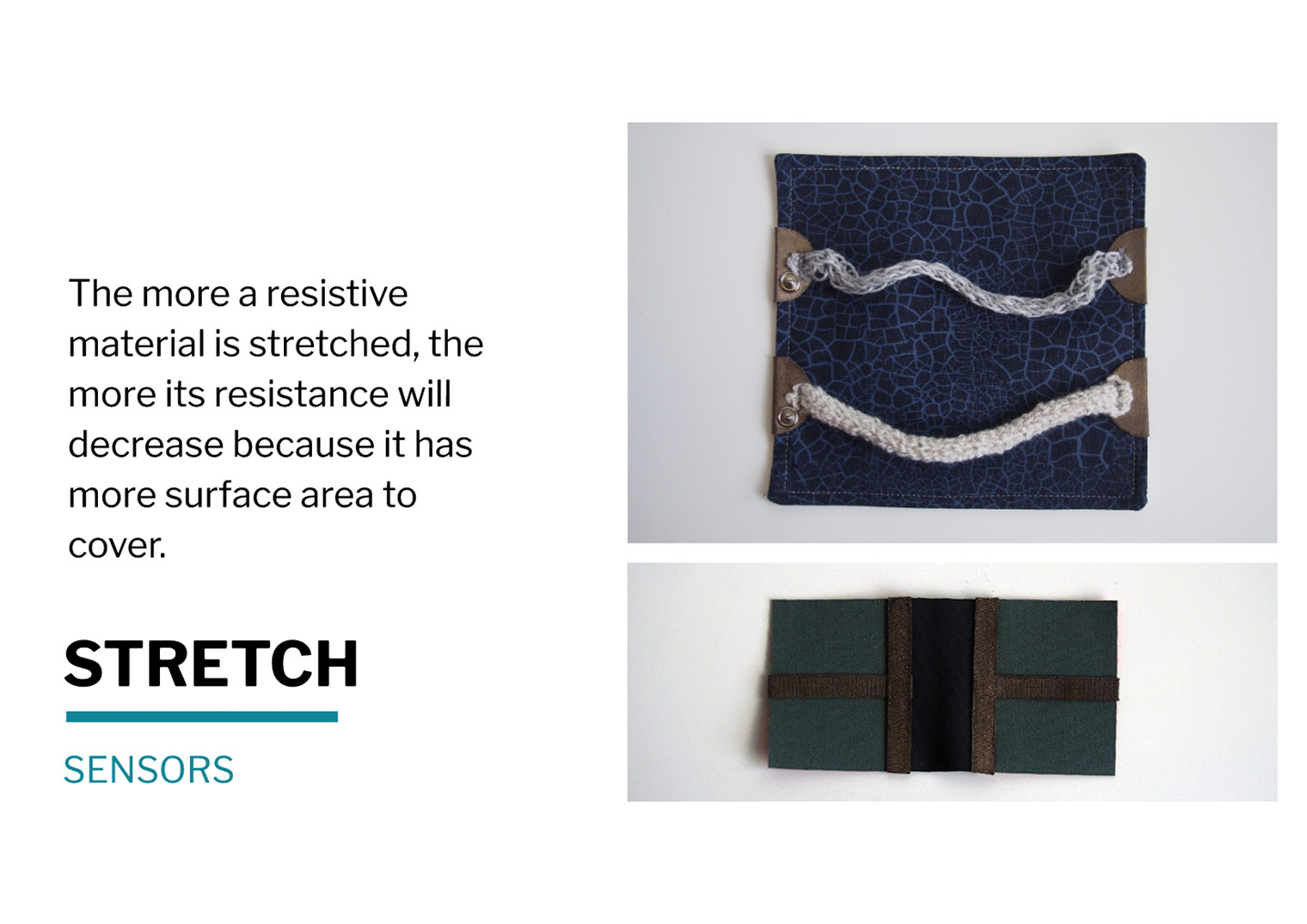
The way in which analogue resistance works:
The input resistance can vary and therefore affect the output.
The resistance can be affected by either: Pressure, surface area or distance.
-
Pressure: Materials act differently because they are sensisitve to pressure. The resistance could be less in some when pressure is applied.
-
Surface area: The electricity flow dscreases when increasing the size of the surface area.
-
Distance: The more distance, results in an increase in resitance. In any material.
Programming - Arduino
Number 1 rule !: Always plug your board out of your laptop before making changes with the jumper wire or other!
Explain the different stage of controlling the Led light using Arduino.
What we did: We used the Arduinosoftware in three different situations:
-
Controlling a LED.
-
Controlling a sensor.
-
Controlling a LED based on the interaction with the sensor.
Remember, different LED lights need different voltages! There are many LED resistor calculators online.
LED Blink exercise:
Software:
-
Open – Tools – select your laptop (Port usb. Modem) if it is a Mac.
-
Tools – select Board Uno.
-
File – To find an example of Arduino code: click Example – Basic – Blink.
-
Check your input and outputs.
-
Power Pins: 3.3V/5V power: Ground - , Power +
Definition:
Breadboard: Physical support for temporary circuits + prototyping, require no soldering.
source: Learn.sparkfun.com
Breadboard basics:

If you connect your resistor + LED on one horizontal line – they’re connected.
If you connect them on a vertical line then they’re also connected.
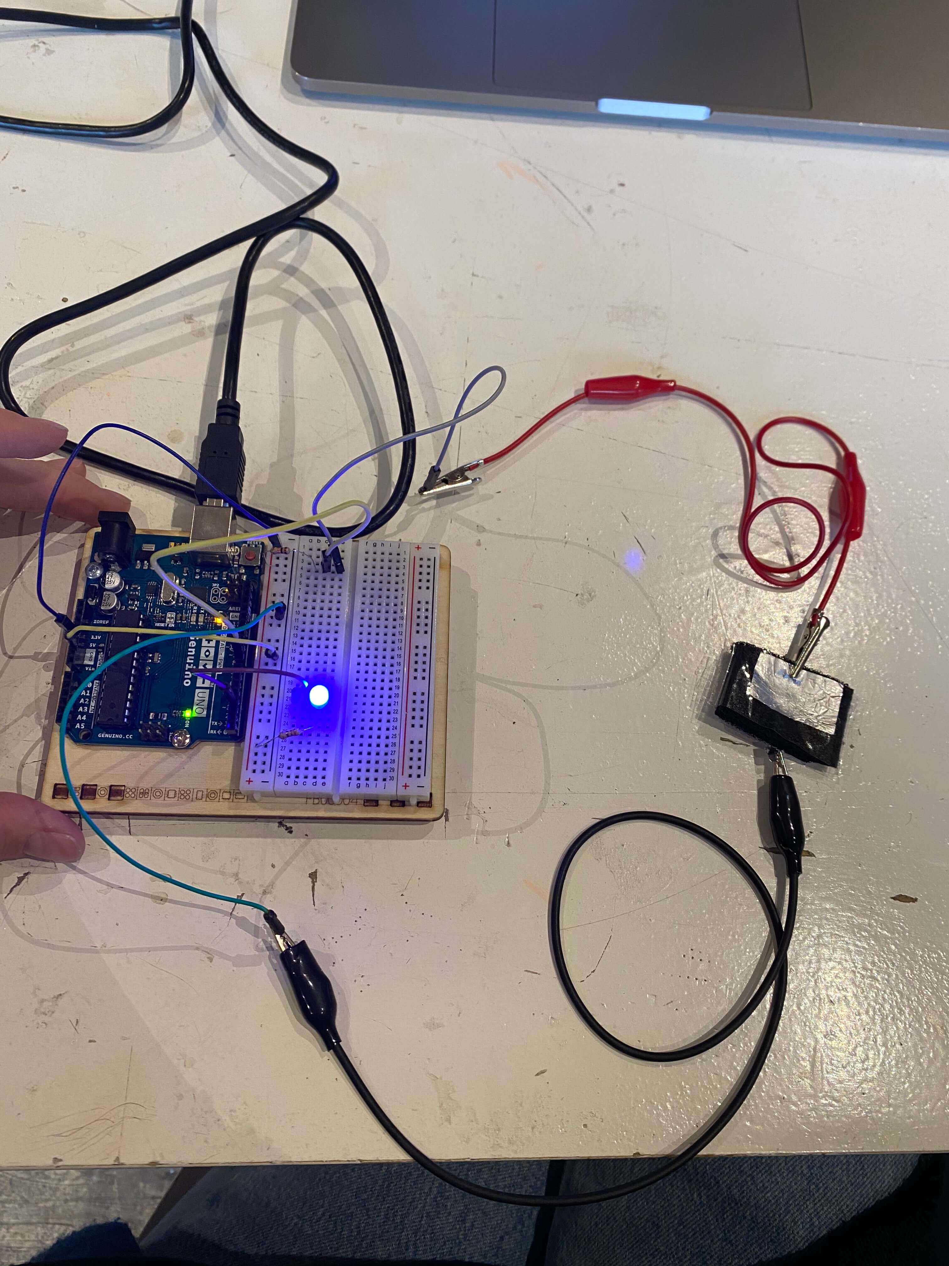
- LED Blinking:
Firstly we had to get the light to work by recreating the schematic physically and then to adapt the Arduino code.
The resistor was at 220 Ohms.
Secondly, we had to download the blink file and then upload to our sketch.
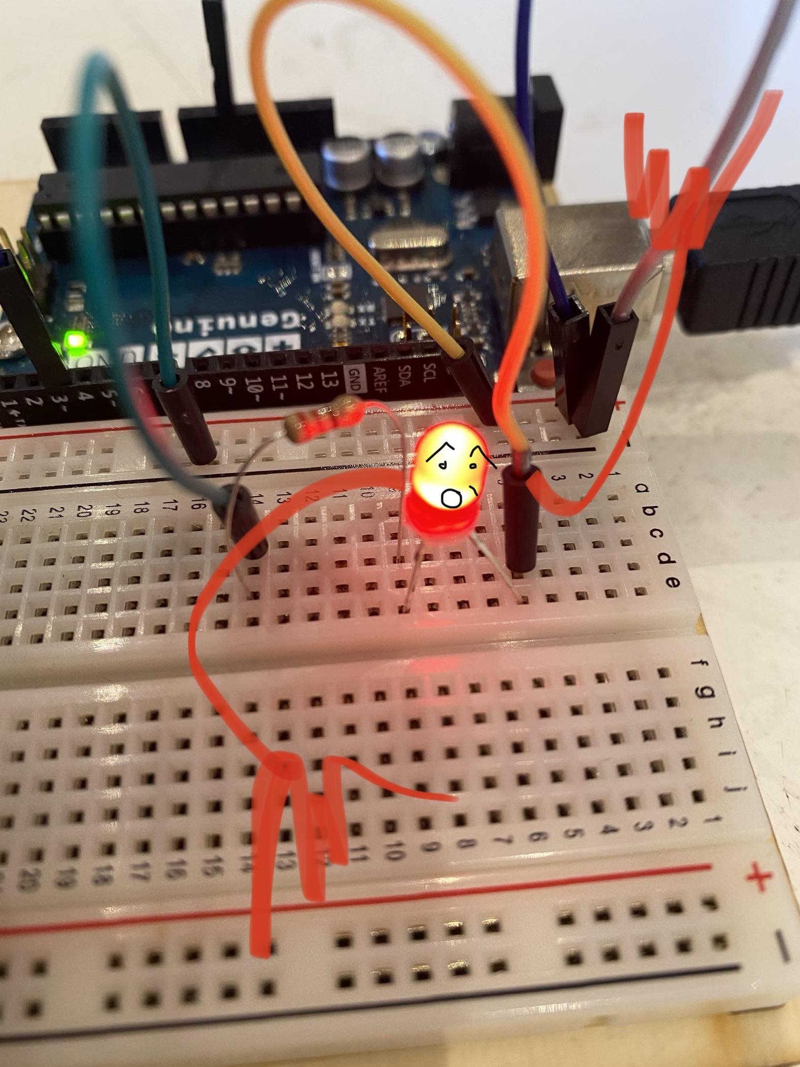
Led circuit:
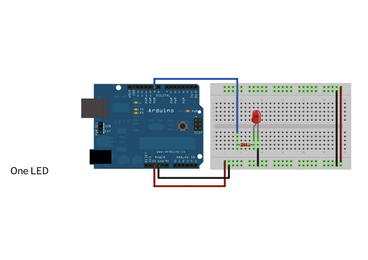
Photo of the blink code:
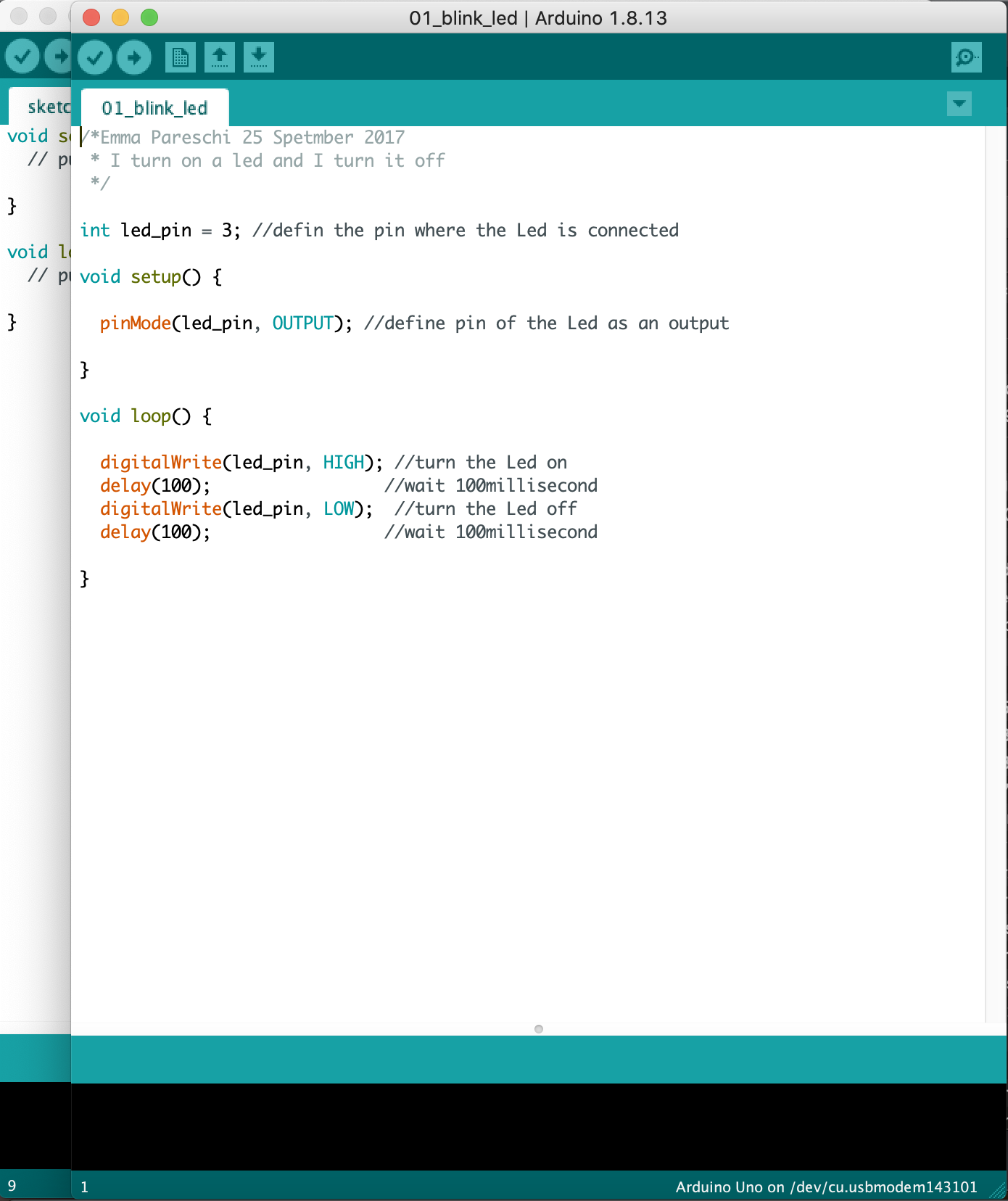
My first digital circuit :).

Analysing the code:
Void setup (): Means that it runs only once, at the beginning of the loop.
Void Loop (): Means Runs repeatedly after setup.
Check the blink LED file and under loop: change the (LED- pin, Low) to (LED pin, High). High in this case means 5V.
Changing the speed of the blinking(slower): From 1000ms or 1 second to 3000ms or 3 seconds.
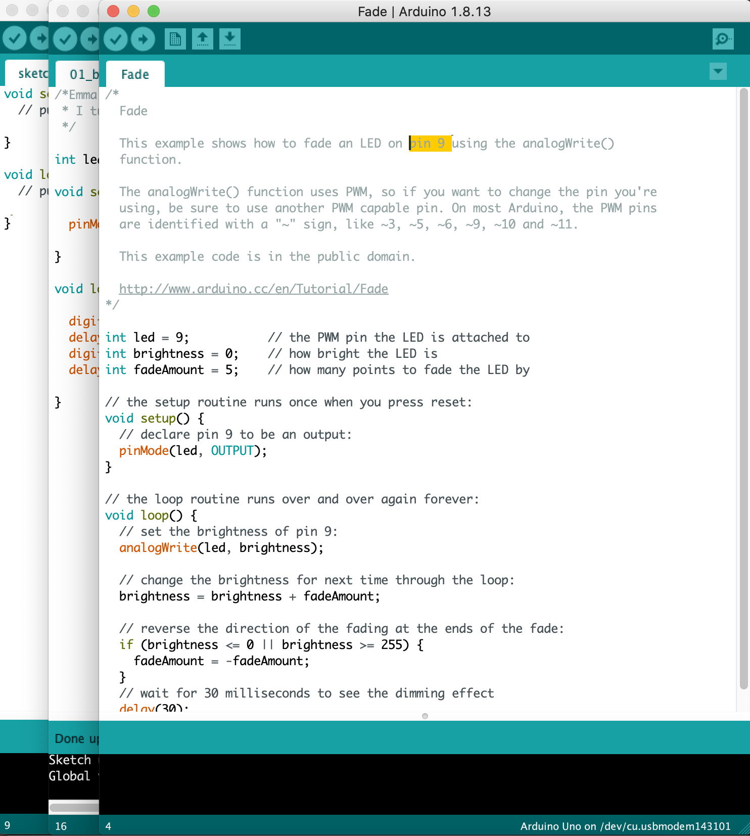
- LED Fading:
Same set up as before.
Upload the file once.
Plug your wire into no.9 in the Arduino.
Controlling a LED based on the interaction with the sensor:
First test this circuit with your sandwich tinfoil switch.
A 10k resistor is used for this circuit.
Open the 03 digital translator. Upload for the switch function. Tools – serial monitor. If you see a change from 1 – 0 , you’re circuit is functioning properly. Like an On/Off switch.
When you press on your tinfoil switch – you should be receiving 0.
Next level: add the LED light to the circuit.
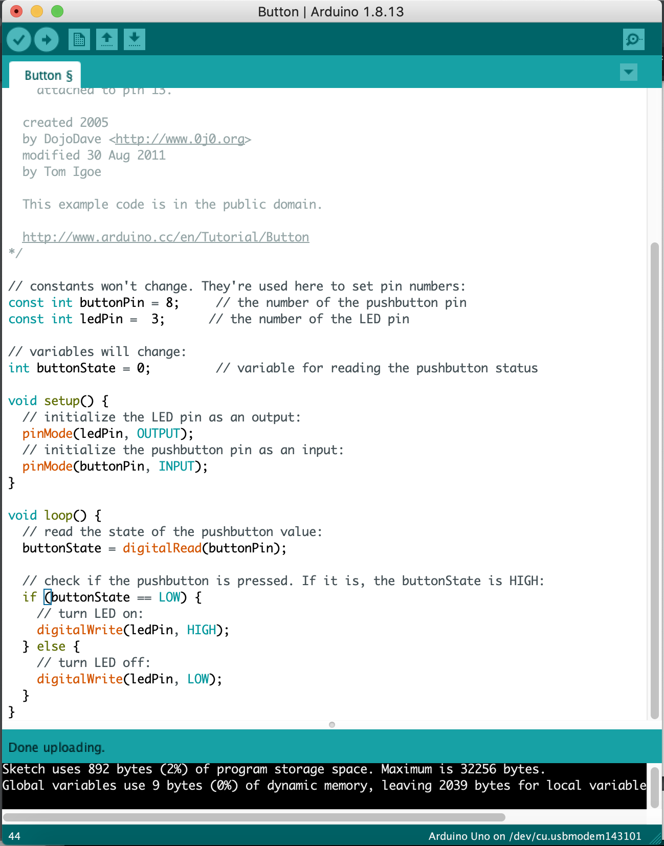
File – Example – Button.
Change: Const Int B.Pin = 8
Cons tint LED pin = 3
This allows the light to turn off when you press the switch.
To change the behavior of switch.
Change button state to LOW and upload.
Change HIGH and LOW according to your preferences.
Photo of the fading code:
Digital sensor inspiration:
As you can see my attitude towards this module was al ittle grumpy, I guess I just wasn't prepared to tackle all the complications that were on their way. Though I must say after this week of knowledge, I turned to be more optimistic. than I thought I would. I guess the results made it worth it in the end!
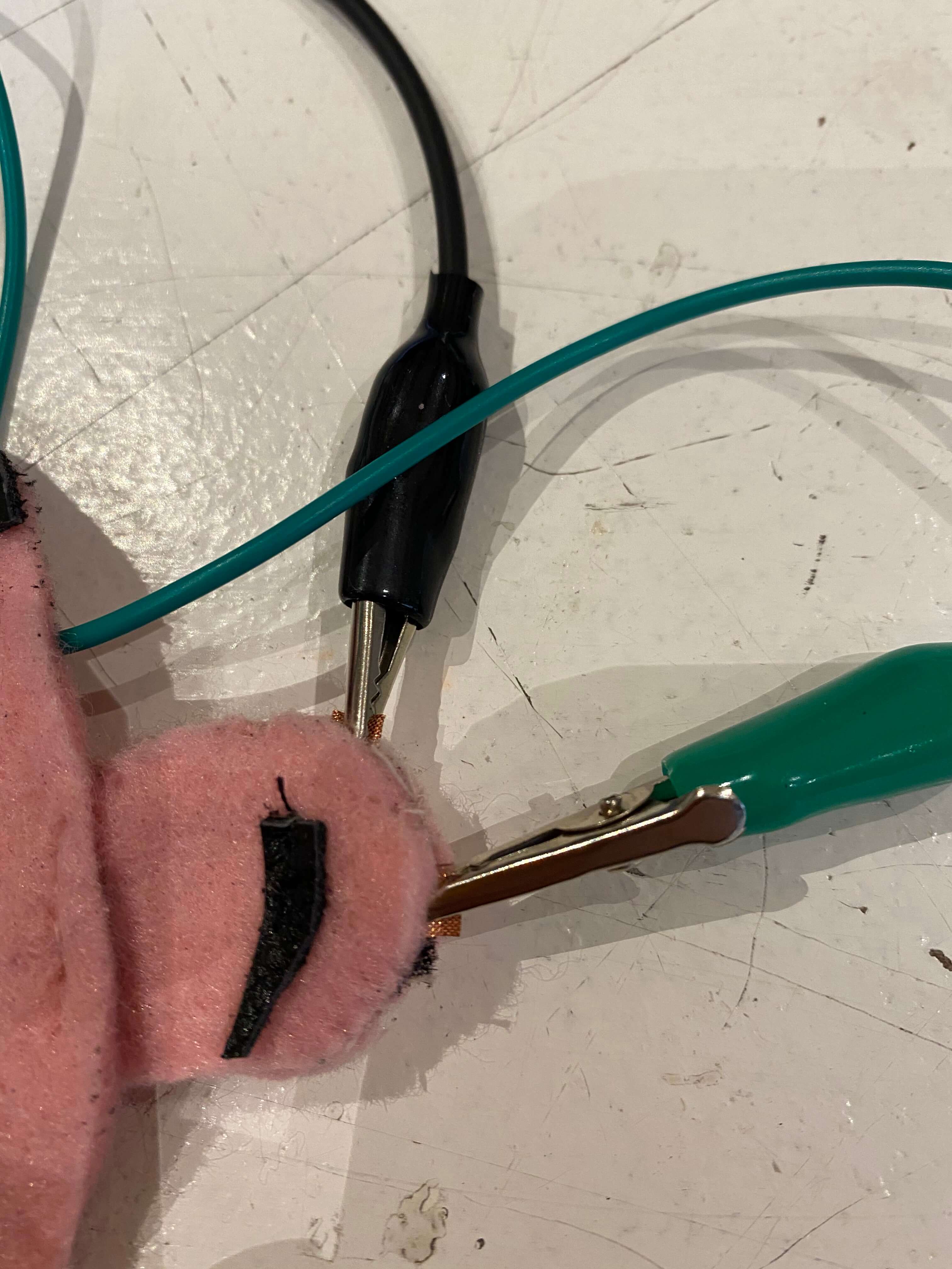
The ear of the "grumpy" man containe conductive fabric and a copy of the foam sensor that we had previously made. This would be my switch for the circuit.
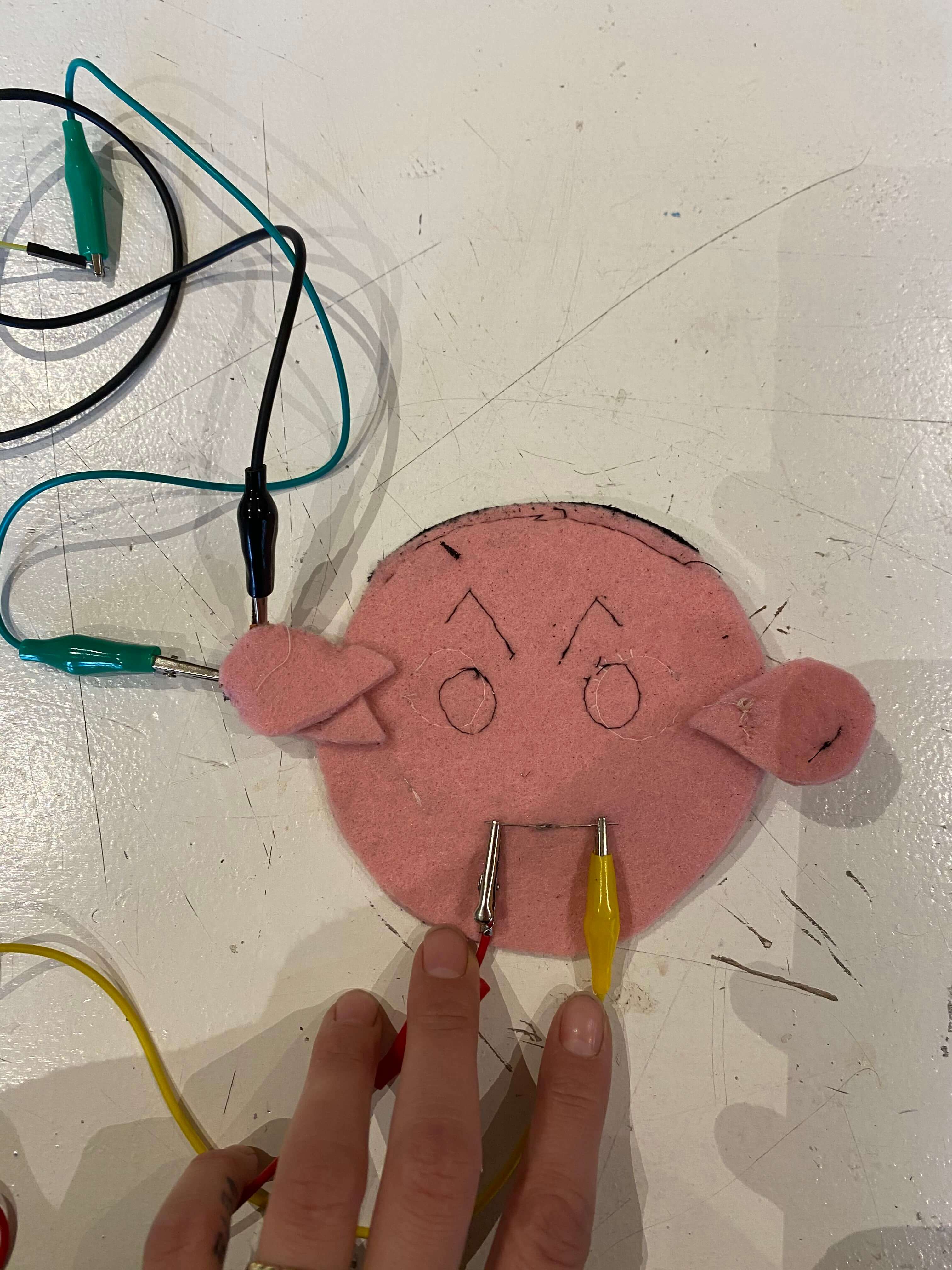
The back side of the grumpy man.
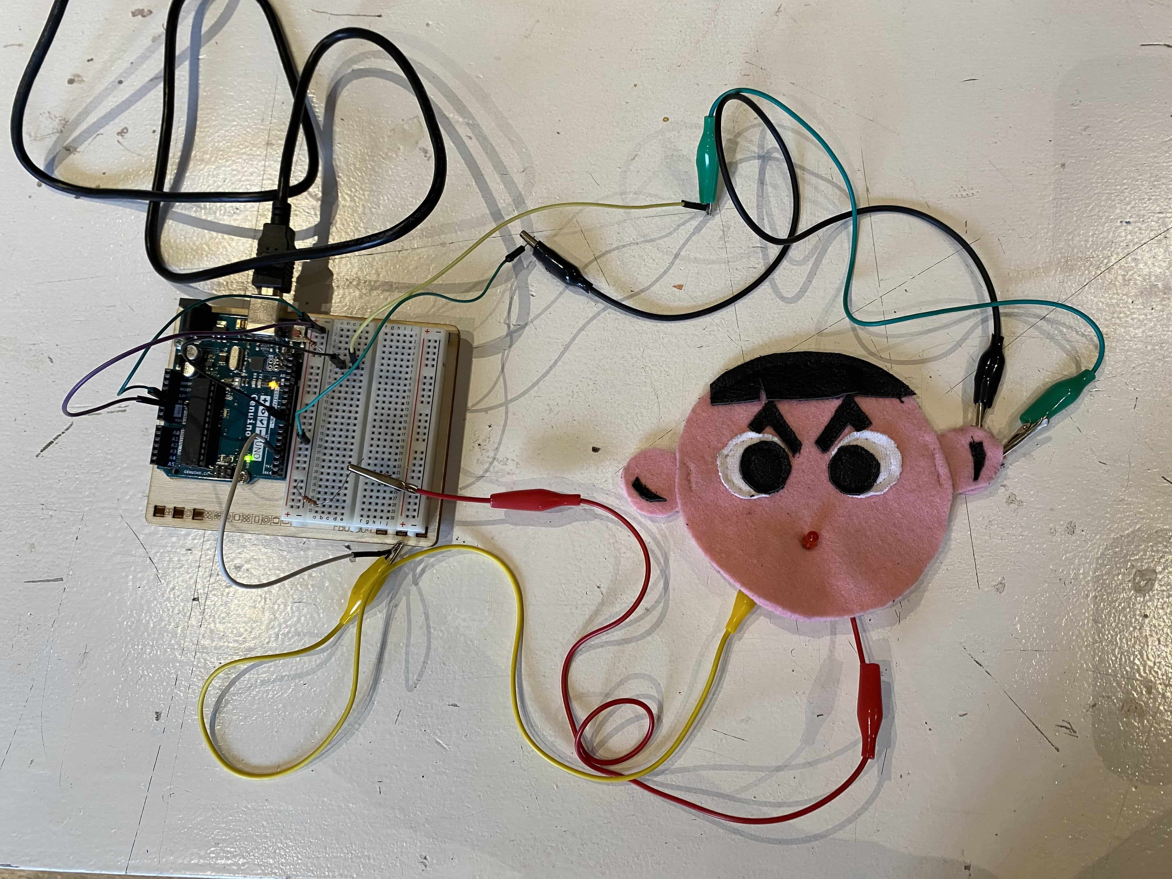
The full circuit once it was completed. The next step would be to make this circuit mobile and portable.
The example of code used for this circuit:
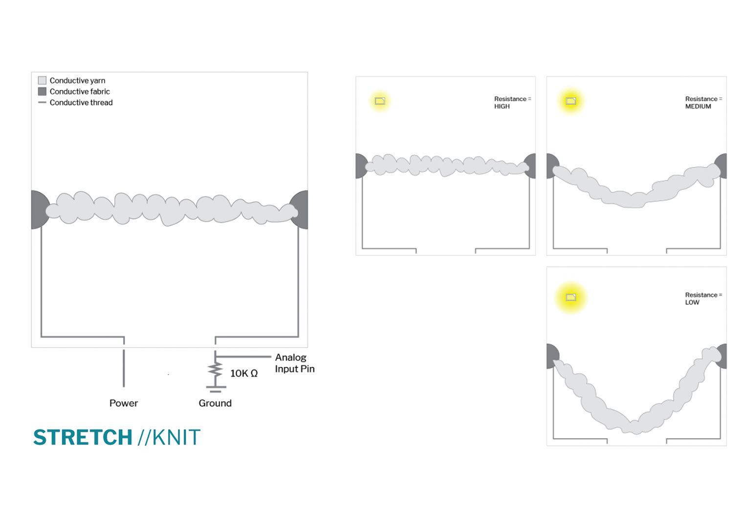
Analog sensor inspiration :

Voltage divider = Analog sensor. For this you look at the Analog side on your Arduino board.
I used Liza starks knowledge for this one seeing as it was a little more complex than the previous deigital sensor. Here were some of the slides that inspired me and gave me an overall feel or idea as to how I should tackle the motion of a stretch sensor.
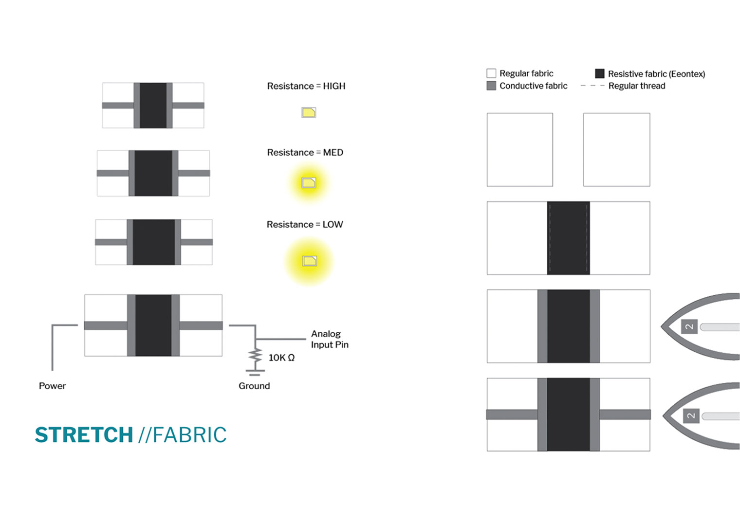
Her website explains it all:
http://thesoftcircuiteer.net/projects/soft-sensors/
Liza's code for the analog sensor (stretch): /* Fabric Sensors October 2018 http://thesoftcircuiteer.net/soft-sensors/ Liza Stark This sketch uses smoothing, constrain, and mapping to read a fabric pressure sensor built with pressure sensitve fabric (such as Eeontex or Velostat) and conductive fabric. Use this for pressure, stretch, bend, and potentiometer sensors. It uses the smoothing example that reads repeatedly from an analog input, calculating a running average and printing it to the computer. Keeps ten readings in an array and continually averages them. It then constrains that value, then maps it to a usable range, and writes the new value to an LED. Smoothing example http://www.arduino.cc/en/Tutorial/Smoothing constrain(value, min, max);
map(value, fromLow, fromHigh, toLow, toHigh) https://www.arduino.cc/en/Reference/Map */
// Define the number of samples to keep track of. The higher the number, the // more the readings will be smoothed, but the slower the output will respond to // the input. Using a constant rather than a normal variable lets us use this // value to determine the size of the readings array. const int numReadings = 10;
int readings[numReadings]; // the readings from the analog input int readIndex = 0; // the index of the current reading int total = 0; // the running total int average = 0; // the average
int inputPin = A1; int ledPin = 9; // select the pin for the LED int ledPin2 = 10; // select the pin for the LED int ledPin3 = 11; // select the pin for the LED
void setup() { // initialize serial communication with computer: Serial.begin(9600); // initialize all the readings to 0: for (int thisReading = 0; thisReading < numReadings; thisReading++) { readings[thisReading] = 0; } pinMode(ledPin, OUTPUT); pinMode(ledPin2, OUTPUT); pinMode(ledPin3, OUTPUT); }
void loop() { // subtract the last reading: total = total - readings[readIndex]; // read from the sensor: readings[readIndex] = analogRead(inputPin); // add the reading to the total: total = total + readings[readIndex]; // advance to the next position in the array: readIndex = readIndex + 1;
// if we're at the end of the array... if (readIndex >= numReadings) { // ...wrap around to the beginning: readIndex = 0; }
// calculate the average: average = total / numReadings; // send it to the computer as ASCII digits Serial.print("Unmapped readings = "); Serial.print(average);
Serial.print("\t");
//change these numbers to the min and max you want to use average = constrain(average, 600, 1000);
//map the average onto a range the LEDs can use int newAverage = map(average, 600, 1000, 0, 255);
//print it out for debugging Serial.print("Mapped readings = "); Serial.println(newAverage);
//constrain the new average again just in case newAverage = constrain(newAverage, 0, 255);
if (newAverage < 1) { analogWrite(ledPin, 0); analogWrite(ledPin2, 0); analogWrite(ledPin3, 0); } else if (newAverage >= 1) {
//write the new value to the LED
analogWrite(ledPin, newAverage);
analogWrite(ledPin2, newAverage);
analogWrite(ledPin3, newAverage);
} delay(1); // delay in between reads for stability
} © 2021 GitHub, Inc. Terms Privacy Security Status Docs Contact GitHub Pricing API Training Blog About
Press upload.
Tools – Serial Plotter.
The next level was to add the sensor to the circuit.
This is an example of calibration.