Week 10: Wearables II.
What did we do this week?
This module is a continued subject from our experimentation in week 5. Having touched on the basics of electronics it was now our turn to take it a step further. We started off by making a power supply for the actuator. Also, we left the diode on purpose seeing as Emma told us that there is no extra safety needed for this circuit.
The three important parts to this circuit (MOSFET): Gate, Drain and Source. At the end of this week will have learnt about actuators and built two of our own as well. These could then later be powered by Arduino or an AtTiny.
Inspiration - Liza:
Sound:
What you need to build a speaker:
- Calico (Cotton/Canvas fabric).
- The conductive thread: Karl Grimm S. Thread or similar regarding conductivity. Form into a type of coil.
- 4 small neodymium magnets.
- ADA fruit mono 2.5W
- Class D audio amplifier.
How to form your speaker:
- Start by sewing a coil from your conductive material. This could be done by laser cutting conductive fabric for example, or simply just wrapping conductive thread around your index finger. You may also embroider on your non-conductive material using conductive thread. When you do embroider however, be aware to monitor the change in voltage. ALso be sure to use the right conductive thread. Some are weaker in strength than others and are therefore at risk of breaking when you start sewing.
Example:
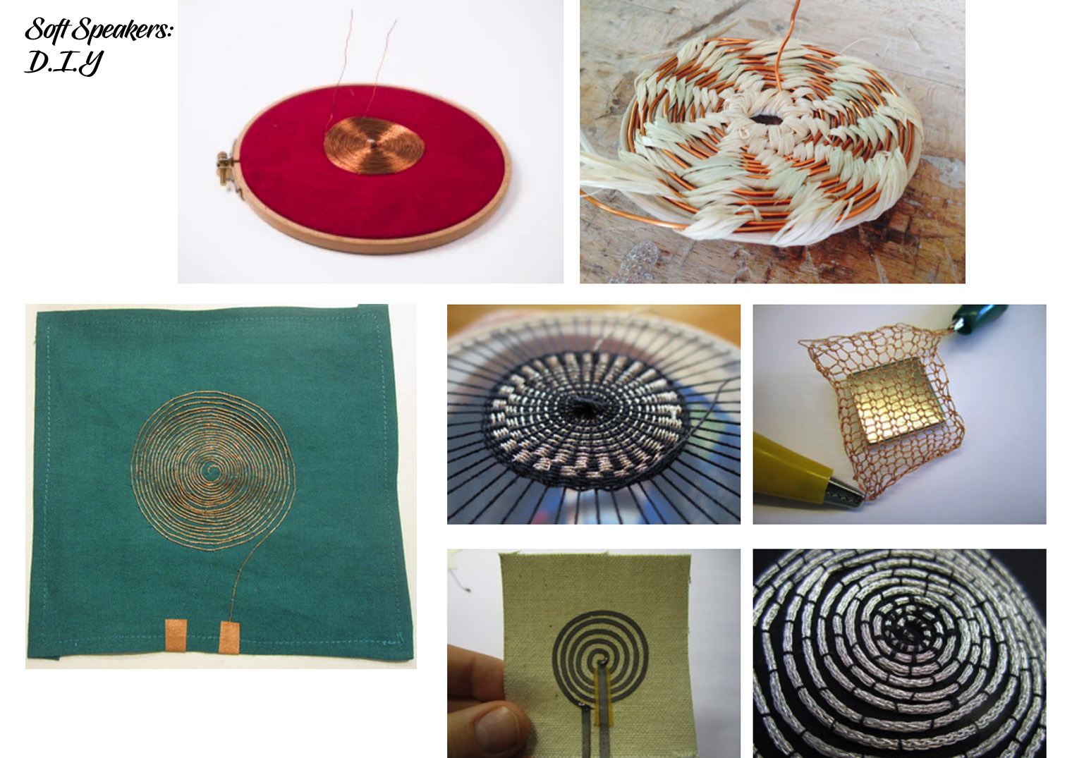
sourced from: https://www.kobakant.at/DIY/?p=5935
It almost seems as if you can make a speaker out of everything. Let's do it.
Programming the Arduino for set functions:
The programming of the Arduino was the first part to the tutorial. The idea was to find out how to drive an output device with the Arduino using a particular code.
Some writing tips in Arduino:
-
Every line in Arduino is a new command.
-
The Arduino speaks in miliseconds ex: 0.5 seconds.
-
Global variables: A variable is a name that holds information.
-
Whenever you put a name after the int. in your code that is the name that your chosen number adopts. Example: 3 = led_pin. So number 3 is named led_pin.
-
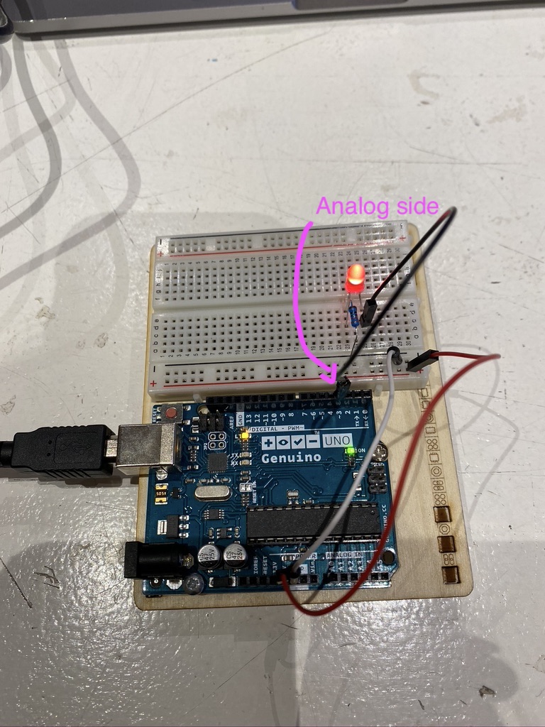
For the analog setting, the Arduino must be plugged into a number on the right side (digital side) of the board. The number must also carry a wavy symbol next to it. For example 3
- After writing each command close off with a ;
First lesson: LEDs.
01 Led – Blink:
Led + switch. Setting the intensity of the LED.
-
Open up the 01 blink LED file in Arduino.
-
Spot the code for the setup () and loop () configuration.
-
Plug the Arduino into your laptop and upload the file.
02_led_analogwrite:
This code explains the analog way of coding. This means that the blinking of the LED can be manipulated by time as well as other factors.
A circuit with a switch sensor:

03 read_ digital sensor:
The first variable for the sensor is the pinmode in the code. Called (Digital_sensor_pin, INPUT).
For your circuit: You don’t need a resistor if you change this exact INPUT code. The positive thing about having to lose the resistor is that you have one less component to worry about. However, changing the INPUT_PULLUP code also means that you will have to change the rest of your code as well. As is explained by Emma.
04Button_led code:
In this code setting we were taught to use this IF value. Example: If such and such then such and such. The “else” means = otherwise. In order to make your If function useful = when you are regulating numbers check the comparison operators table. Check the number for how often you press your switch..
Sketch05:
We were counting our own interaction with our sensor. The example was: We set the function so that If we pressed the sensor up to 5 times, the value would reset to zero.
(Search for a yellow block in the screenshot of 05 counter sketch)
Once we had set the code – open the serialmonitor – If we would press up to 3 – the value would change back to zero again.
06 sketch:
This sketch served as a away to view the different interactions between the input and the output.
The example we used was: Powering an Arduino + 3 LEDS. In this case we powered a Load and a driver.
The MOSFET that we created in class is also a circuit driver.
What is a power load:
According to Emma:
There isn’t a general answer. According to the Arduino application, a Power loads is an output that can’t be supplied by the Arduino I/O pin.
The max current that a 10 pin Arduino can source is 20 mA.
Even without a multimeter you are able to test the energy of your loads. You can calculate the resistivity using the multimeter and then calculate the conditions for your device in which it will operate in. This can be done by powering the device with something other than an Arduino.
Insert slide about how to calculate the Ohms law and power the device. Emmas slide

Transistor:
In our case it was a MOSFET that we built.
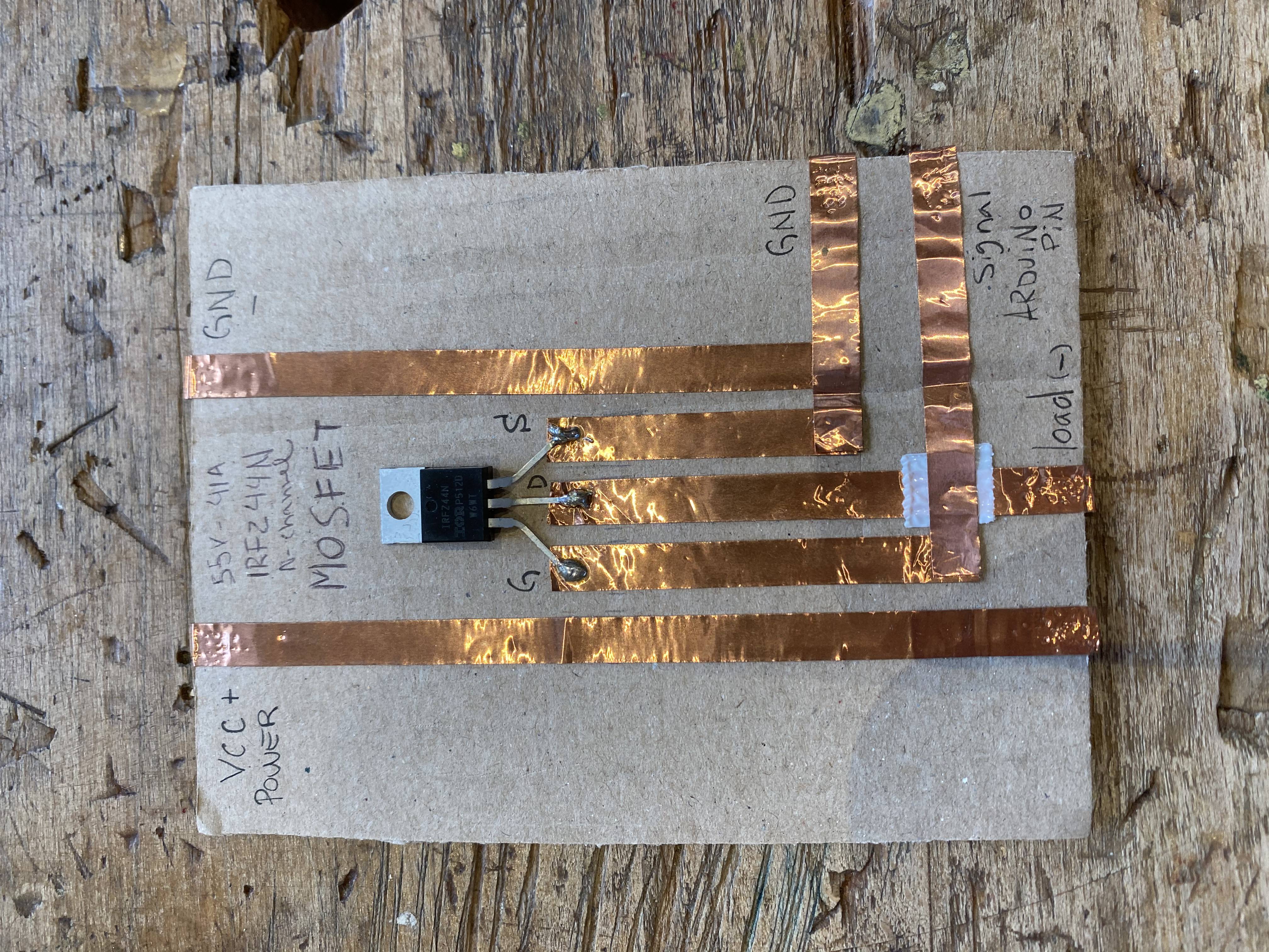
We had to solder the corners because the glue wasn’t allowing for the current to pass from one copper tape to another.) ATtiny: No lessons on this particular dvicee in this module. This will be a self taught topic as I continue to explore the world of electronics.
Electro magnetism:
This concept is handy if you were to work with speakers.
Insert simple diagram from the presentation.
Also flapping win g example and flipping dot example photos.
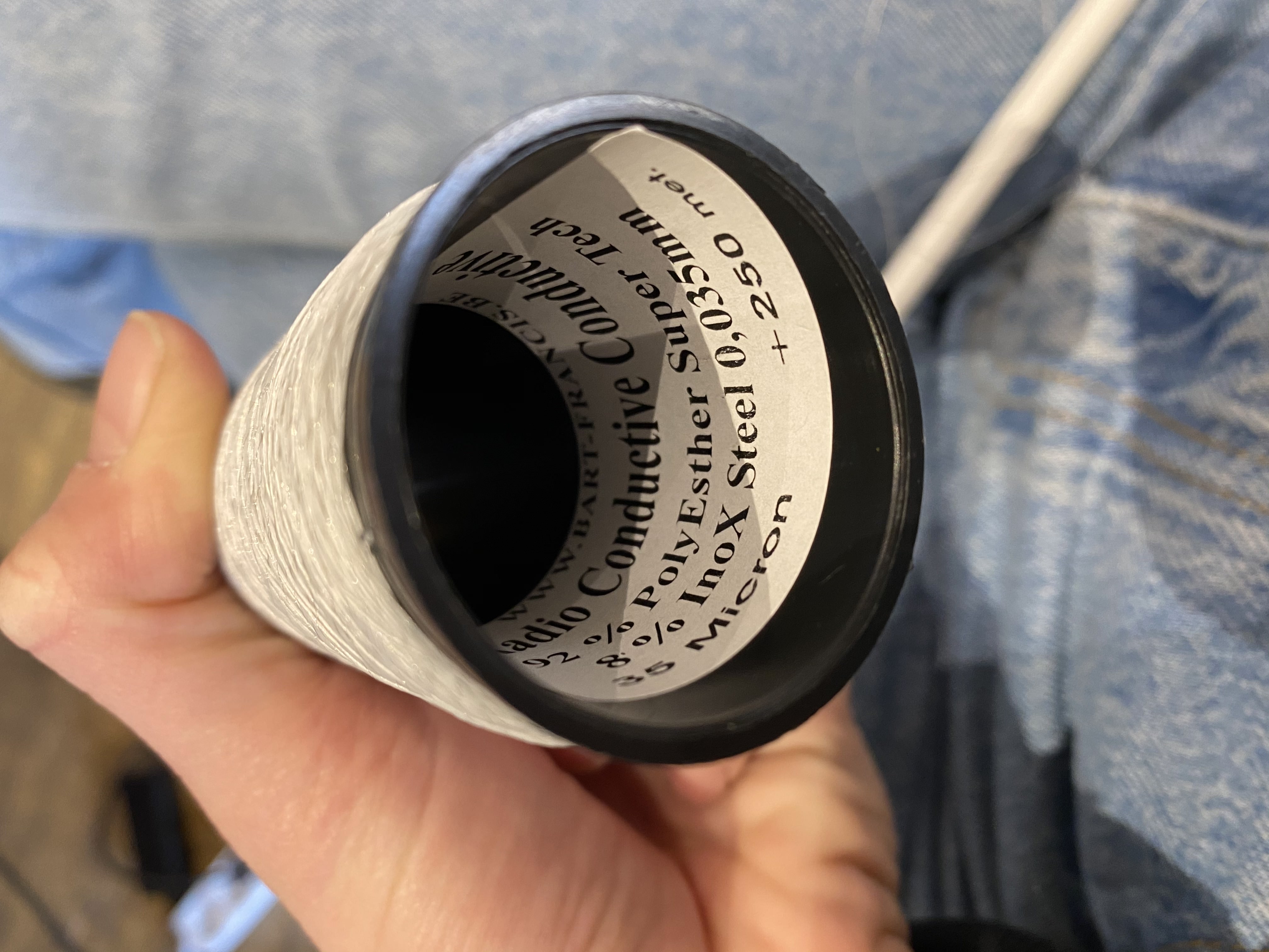
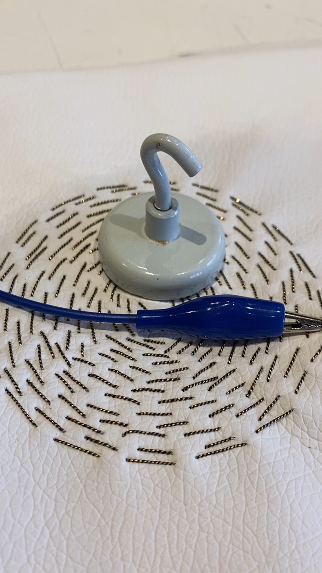
When we worked with electromagnetism, we had realised the copper thread used (image below) would be covered in some kind of insulation coating. A good way to remove this coating from such a material is either by heating up the corners for a few seconds with a lighter, or as Henk said use sanding paper to scratch off the top layer.
Conductive thread:
A good way to power a project is by hacking a power bank to supply you with power.
It is always good to check if you are using the right resistors for the circuits because it may result in a short circuit.
Day 2 Emmas teachings:
On the second day of the tutorials it was our turn to learn the findamentals of programming Neopixels as well as a speaker.
Macrame stretch sensor:
Kobakant had a useful example on their site for a demo piece. The stretch knits sensor.
 the blue stretch sensor.
Neopixel + Arduino: (Smart light)
Sewable Neopixels
https://learn.adafruit.com/flora-rgb-smart-pixels/overview
The Neopixel consists of three LEDS. There are different types such as: Strips, Rings, Matrices and sewable individuals. In order to light upa. Strip of LEDS you just need one Digital pin from the Arduino. Every LED serves for 20 mA, therefore the Neopixel holds a total of 60 mA.
The following slides were from Liza's presentation, a few things to keep in mind when you are ready to work with neopixels.
![]()
About the power: The Arduino can hold no more than 10 neoPixels at a time. If the idea is to power more than 10, check Emmas slide on power slide
![]()
The code:
![]()
Another tip is that you must always check the orientation of the capacitor, if you place it wrongly the circuit might explode.
For this lesson: we needed to download libraries. We downloaded the ADAfruit library Strand test.
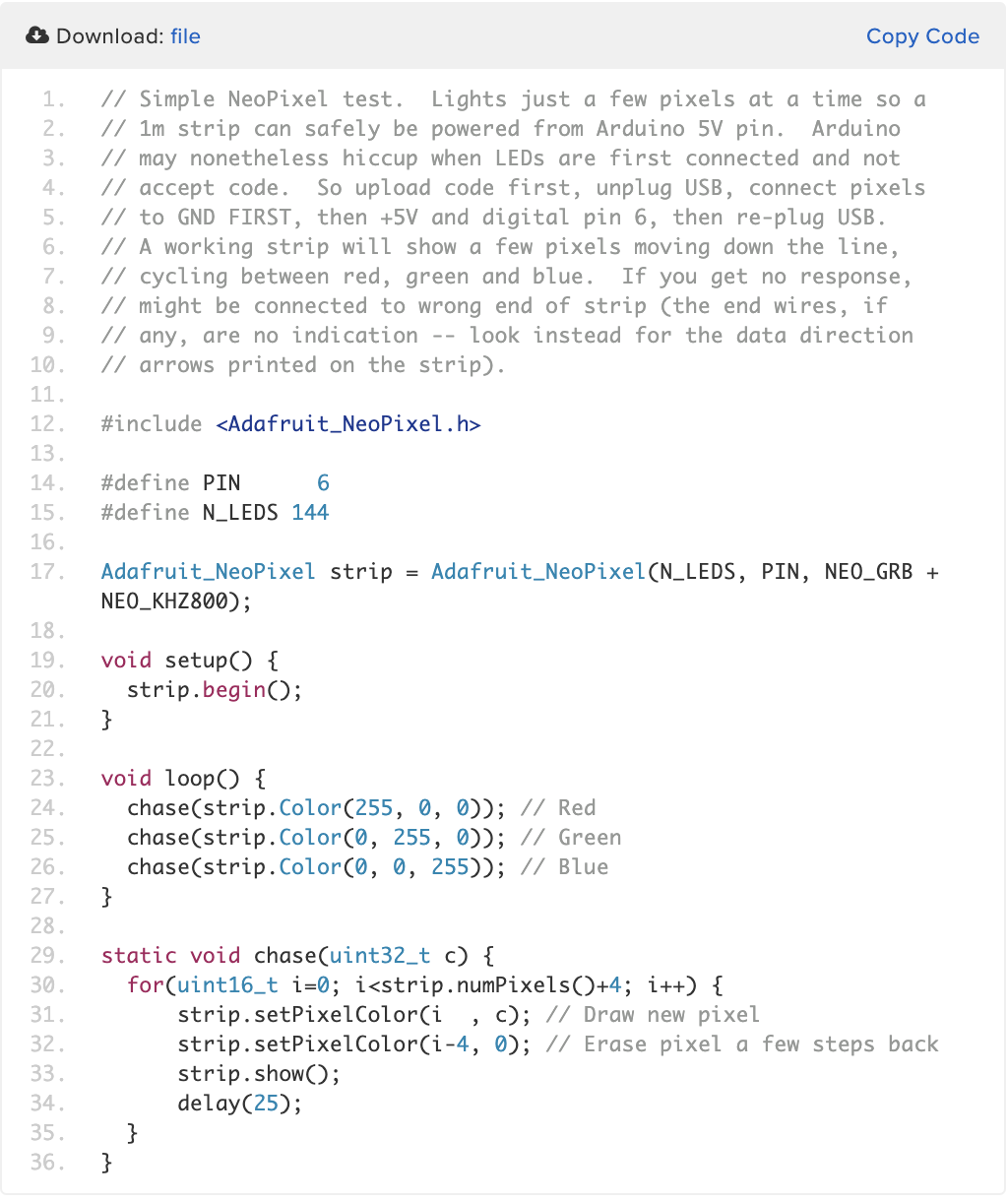
01_NEopixel_Analysin:
Open file. In this example our object was named PIXELS in this file. PIXELS = ADAFRUIT_NEOPIXEL (NUNPIXELS, PIN, NEO_GRB + ENO+KH2800) this is a normal configuration for this code.
Example:
VOID_SETUP:
Pixels.begin();
Brightness.
Voidloop();
Pixels.SETpixelcolor (0,255,0,0,) These are the order of the colours: the first light LED, R,G,B) This to define the colour of the Neopixel.
The task here was to try edit the UNIT32+, 4 different commands for 4 different colours.
02_Neopixel_full:
Take the variables and place this in the text.
03 sketch file:
This function doesn’t come from the library that we were using before.
Example:
Void loop()
Voidcolorwipe(unit32_t,color,int wait){ This is the written function.
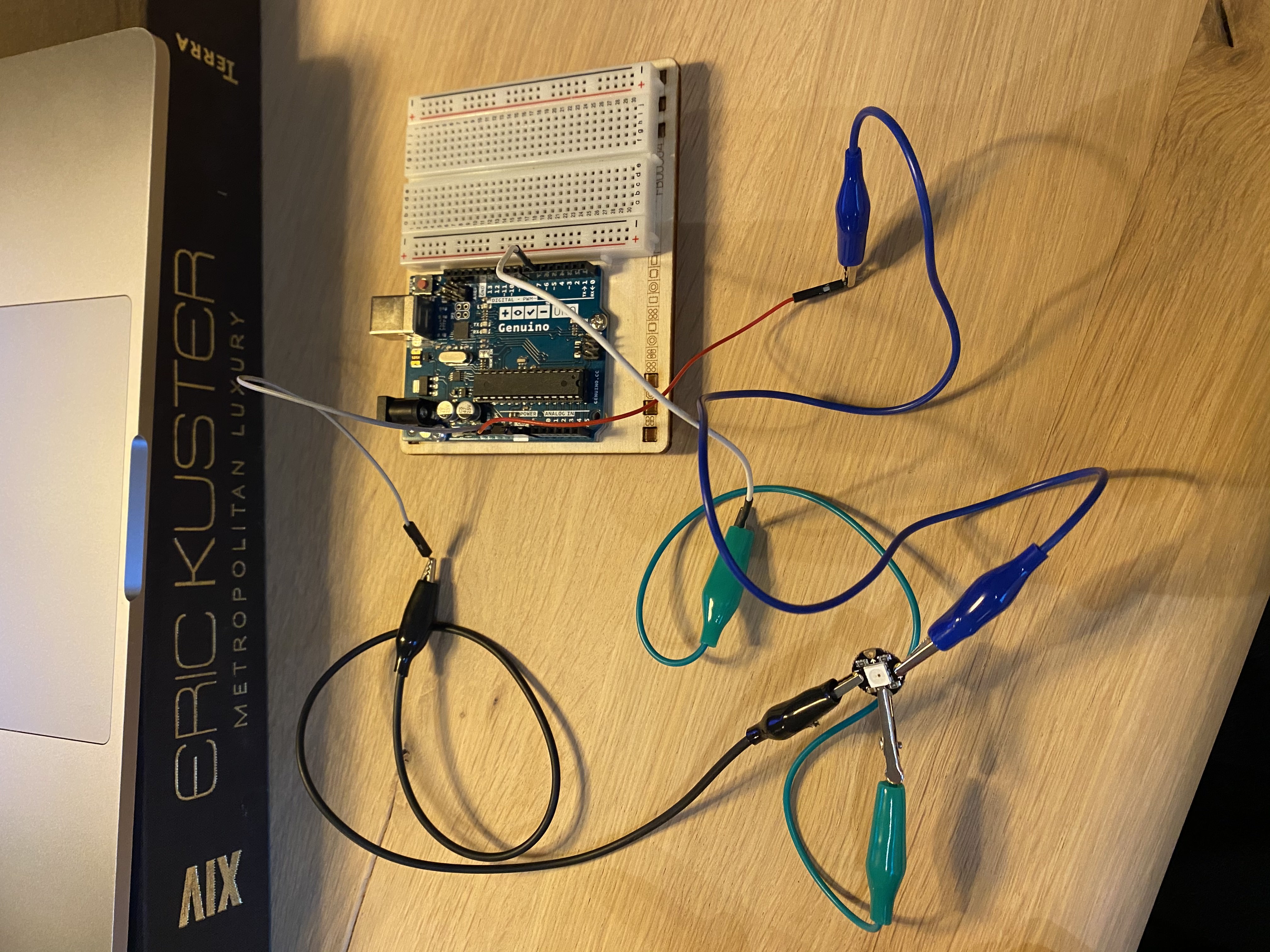
Adding the switch to this circuit:
Rainbow switch was the mission. The difficulty here is that my Neopixels are separate components. This meant that I had to use several alligator clips to hold the circuit in place and connected. I wasn’t able to connect more than one neopixel to my switch.
05 analog sensor:
This code drew my attention. Perhaps this will be used in a future project of mine.
The setup:
A little disco show with the lights:
Sound workshop:
Follow Lizas slide on page 65 for more information about this topic. The focus laid on electromagnets and how they were activated through the use of a softspeaker.
The three ways to generate sound were as follows:
-
Generate a sound with an Arduino speaker.
-
Play the music of your device (iphone/computer) on the speaker.
-
Play tracks from an SD card on the speaker.
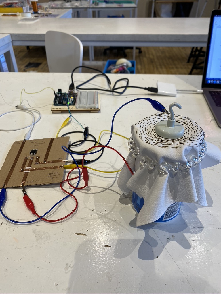
07 sound sketch – exercise for the soft speaker test.
In the code you should define with pin no. connects to the speaker. In this case it is pin no.3. Then we insert the text: //tone(pin, frequency). When we connected our circuit and test the softspeaker we make sure that the conductive threads for the terminal weren’t touching eachother.
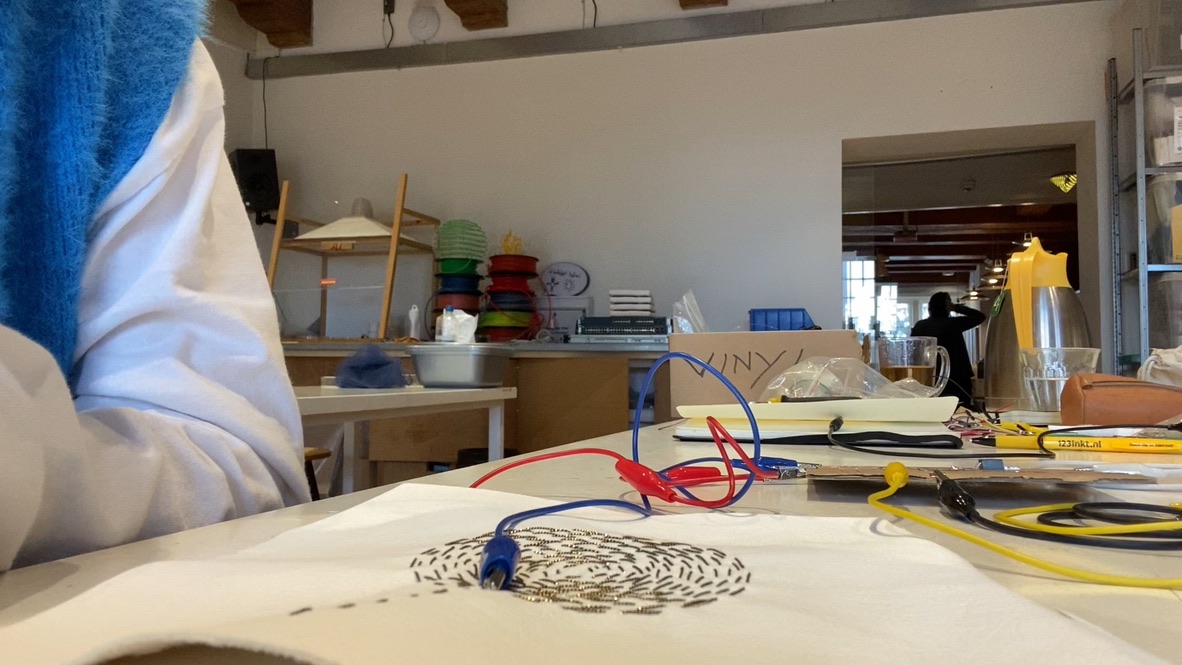
Here is what I created: The Result of my soft speaker on a yoghurt cup.
Closeup:
This week I was very limited to my experimentation therefore I advise you to check our Rebecca Brauers or Pailinas page for her amazing flippermagnet. This actuator can be found following lizas Starks presentation page 101.
For the flip dot actuator you must first get rid of the enamel. Either burn off the tips or scratch it of with sanding paper. Show the process of sewing this one and also the battery pocket.
The problems I faced during this exercise:
-The MOSFET board wasn’t functioning properly.
- The magnet that I was using to activate the softspeaker wasn’t strong enough and therefore it had to be replaced by a bigger one.
- The conductive thread did break a few times when embroidering. If the copper thread is broken the connections are also lost.
Useful/Interesting links:
- https://vimeo.com/483202970: Lisas presentation on wearbles.
- https://www.kobakant.at/DIY/?p=2936: How to make a softspeaker, Kobakant.
- http://thesoftcircuiteer.net/projects/fabric-speakers/: Lisas explanation about the basics behind building the circuits.
- https://www.nature.com/articles/s41598-020-65003-2. Nice article.