Week 7: Computational Couture
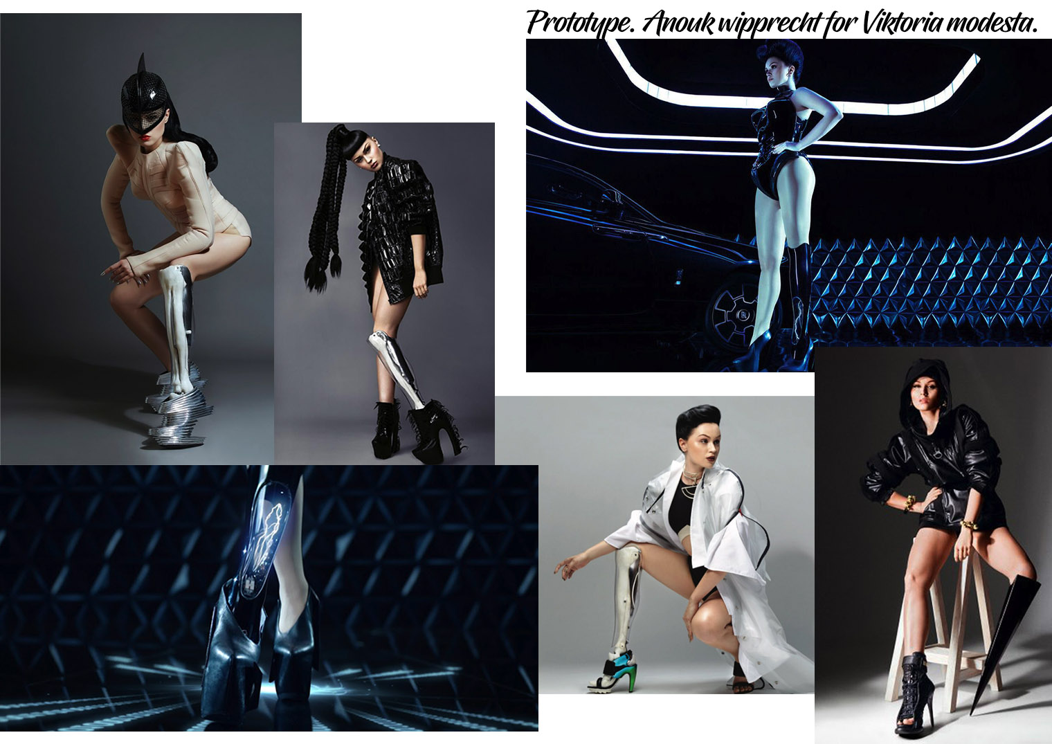
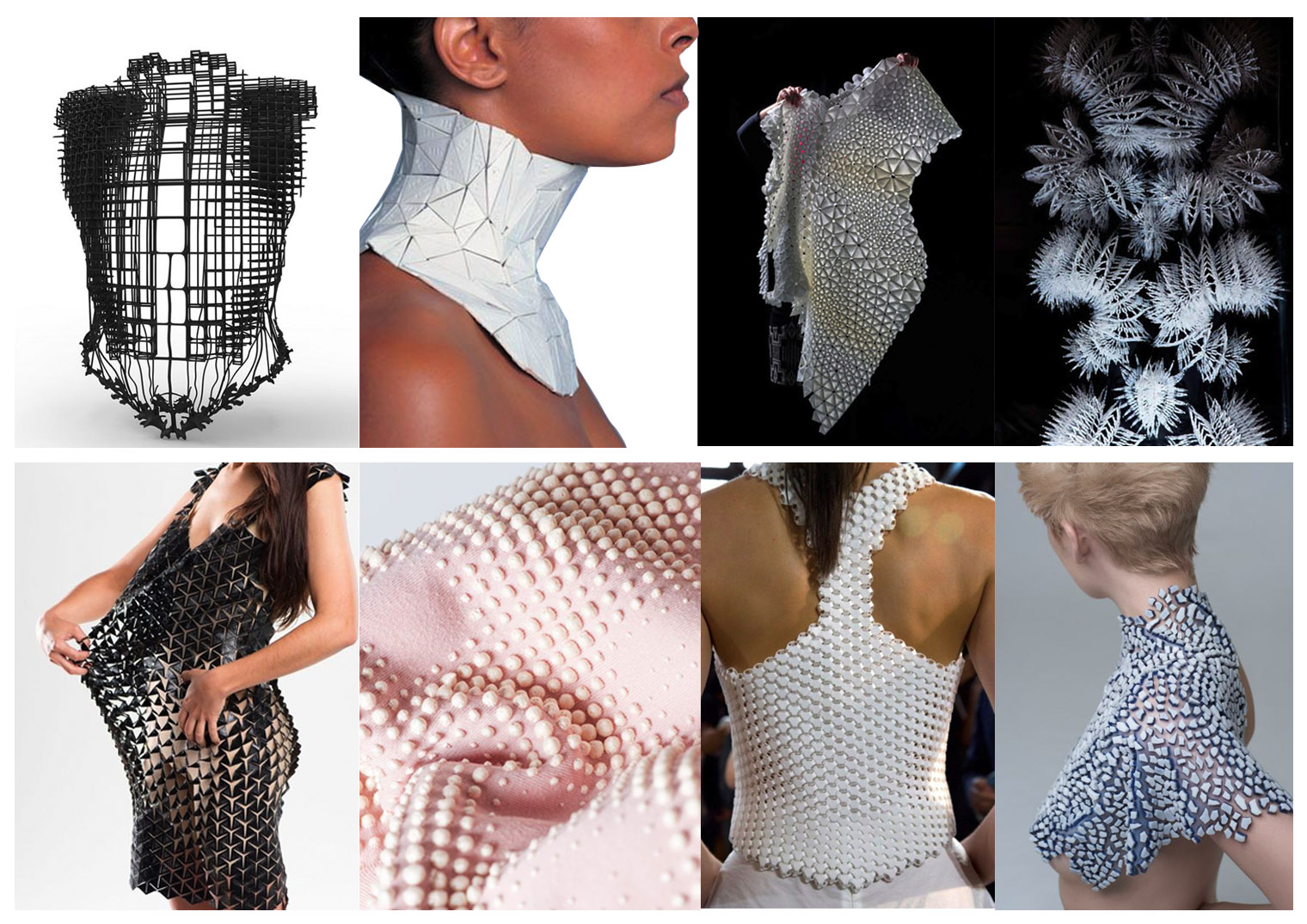
Inspiration for designing in the future:
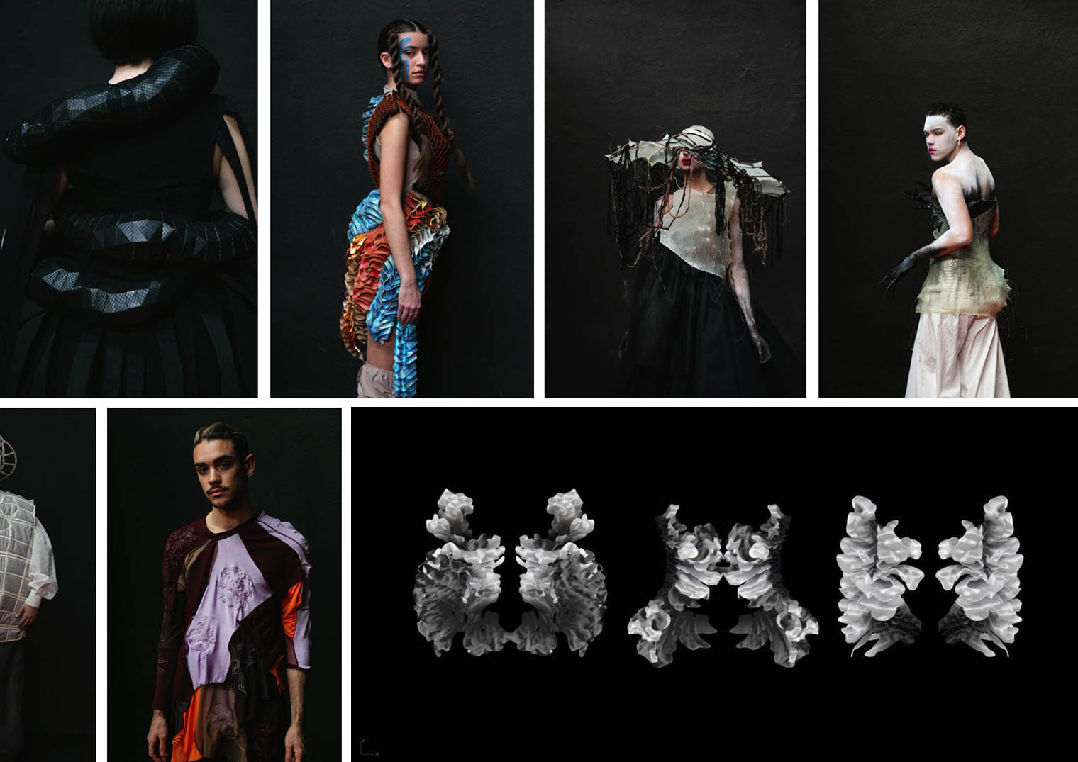
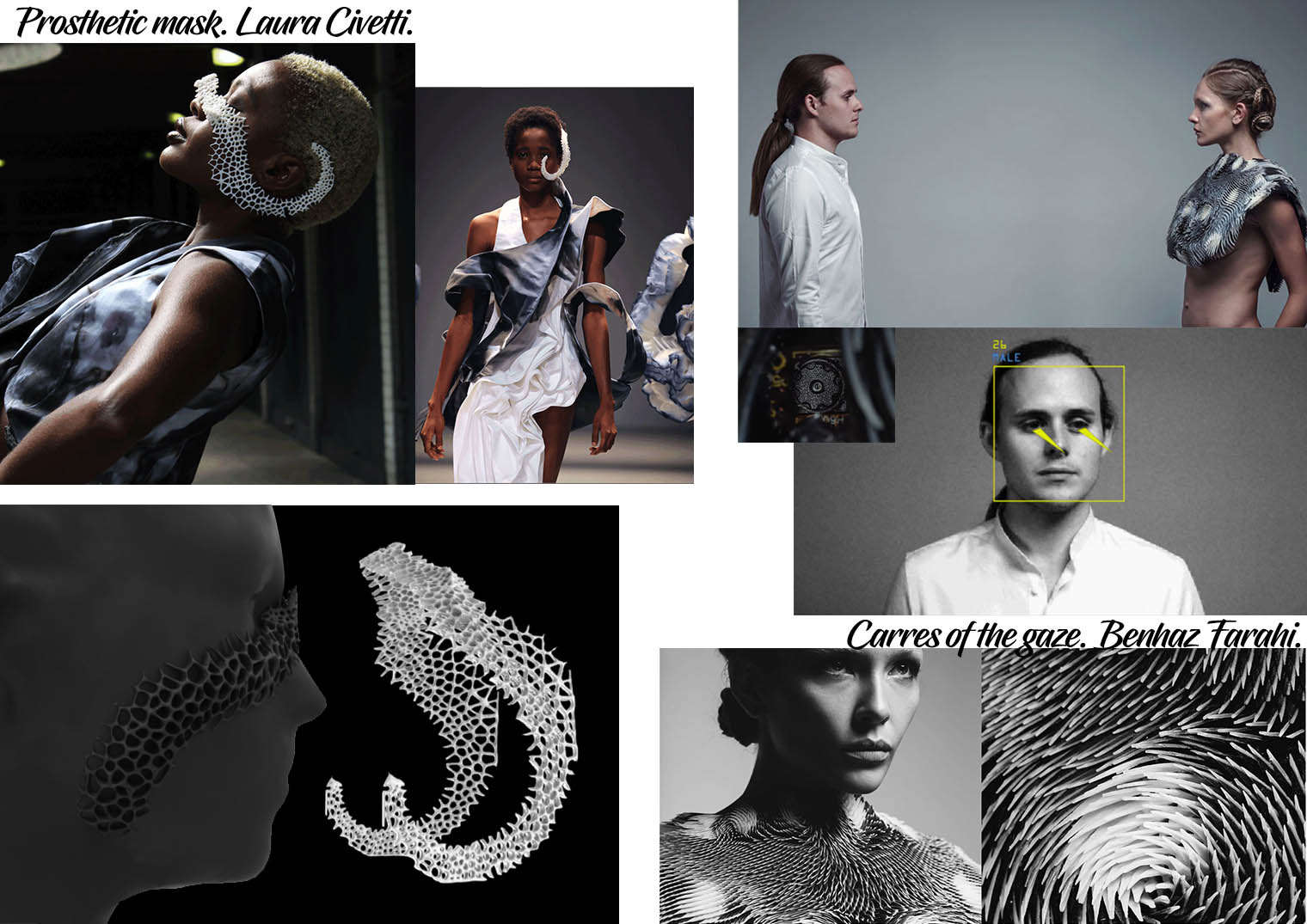
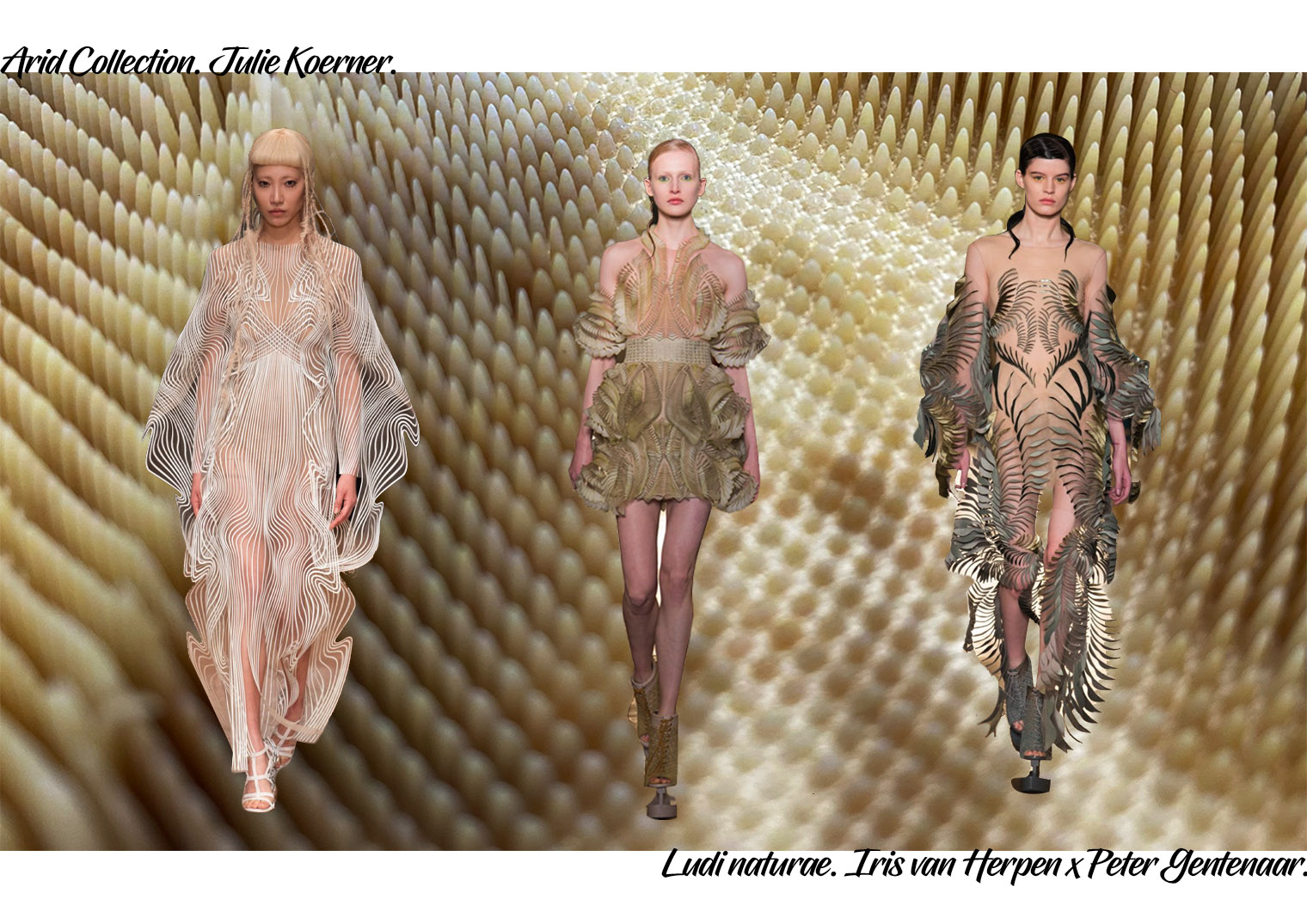
Artist inspiration:
Research
Disciplines as programming and electronics become highly interconnected, blurring old boundaries and merging different fields of knowledge. Fashion has been already affected by this radical change. Therefore, clothes, shoes and other accessories can now incorporate elements of hardware and software, generating a peculiar mix between fashion and computation that is incredibly fertile and inspiring. Data becomes Beauty, Interaction becomes Emotion. As a result, a new aesthetic is emerging.
In this class participants will explore computational design methods towards a new reinterpretation of cloths, garments and accessories for fashion design, inspired by a new digital design methodology.
This class requires basic knowledge of Rhinoceros, Grasshopper. Participants should bring their own laptop with a pre-installed software. The software package needed has no additional cost for the participant (Rhino can be downloaded as evaluation version, Grasshopper and plugins are free). These softwares are subject to frequent updates, so a download link to the version used in the workshop will be sent to the participants a few days before the workshop.
source: Our lecturer Aldo Sollazo.
Useful links: Beginner tutorials:
-
Parametric modelling in Rhino using grasshopper: https://www.youtube.com/watch?v=uX4ueZ_cYnI
-
Getting started with Grasshopper: http://wiki.bk.tudelft.nl/toi-pedia/Getting_Started_with_Grasshopper
Basic grasshopper:
Brief definitions:
Parameters: Variables in the components.
Components: Functions, different operations.
Connections: Flow.
In grasshopper there is a left to right logic. Colour system:
Grey: The component has information – Good to go.
Dark grey: Data or geometry that is in the component is hidden and not showing.
Green: The component has been selected.
Soft grey: This is a disabled component.
Orange: There is nothing on the component.
Red: Something is wrong with the component.
Basic elements in grasshopper:
Symbol of man with blinded with a cloth – Hidden preview. This command is super handy if you are making more complex designs. It can get super messy once you start connecting each component.
Baking (egg symbol): Is when you convert your grasshopper visualization into actual rhino geometry. Select Sfr… hit bake. Go to rhino – hit shaded view.
Saving files: Always save both your rhino and grasshopper files individually. .GH is the file name.
source: https://www.youtube.com/watch?v=XHqiD-qXGA0
Tutorial steps:
-
Insert Param (Insert icon) These store information. Parameters and components are two different things. Parameters don’t have either inputs nor outputs. Insert sketch of diagram in your sketchbook. For your to disconnect your lines: Hover over an output, press your control key and drag you connection backwards.
-
Match your component to your 4 rhino points. How does grasshopper work? You can create relationships on the grasshopper canvas but the preview is on Rhino. Any change that you make in the change of geommetries, will form your definition in real time and automatically update it. (check if this is what he said in the video).
-
Dividing your component into several points is done by adding divide surface component. Connect this to your component via points.
-
To move up: Type move command. Connect the geometries on move component to the points of Sdivide (right side).
-
Also type the z vector command.
-
Add number slider using command. This is to control the distance between your two layers on the z vector. Set the maximum value to 9. Slide to increase or decrease the height.
-
To connect the points from the bottom layer to the top one, insert a line component. (Insert symbol).
-
Plug the start point (Left A) of the line into Sdivide. Plug the end points in the move component (geometry).
Insert photos of your process here: collage perhaps.
Design a parametric model using Grasshopper3D and uploadthe rhino file + grasshopper files. Design files and code must be present in the archive in generically readable forms such as DXFs, STLs, etc. Since rhino, illustrator and other programs are not opensource, use these formats for global compatibility.
Second attempt Basic grasshopper:
Version 2: Grasshopper hexagonal shapes. “Easy grasshopper Tutorial – Basic of grasshopper – GS03: - youtube
-
Open Rhinoceros and Grasshopper programme. Open new documents. All in grasshopper:
-
Enter the hexagonal command on the grasshopper canvas.
-
Enter a number slider command on the grasshopper canvas. Enter 20 as a value.
-
Connect the number slider component to the hexagonal size (S) input. Set the size number to 5 on the number slider.
-
Enter another number slider command. Enter 20 as a value.
-
Connect the second number slider to extent X (Ex) input and the Extent Y (Ey) input. Set the size number 7 on the number slider. You may always adjust the number later on .
-
Enter Area command. Connect the Cells( C ) output from the hexagonal to the geometry (G) input from AREA.
-
Enter Circle (orange colour) command, connect the centroid ( C ) output from AREA to the plane (P) input from circle.
-
Enter Boundary surfaces command. Connect the circle ( C ) output from CIRCLE to the Edges ( E ) input from the Boundary S.
-
Connect the Edges ( E ) from Boundary S. to the Hexagon cells ( C ) output.
-
Enter Distance command, connect Point (P) from Hexagon output, to the Point A (A) from the Distance input.
-
Enter Division, connect Distance (D) output from Distance command to Division (A) input.
-
Connect Result ( R) From Division output, to Radius ( R) from the CIRCLE command.
-
Enter Construct point, connect Point (P+) output to point B from Division.
-
Enter a new number slider with a value of 50. Connect this to Point B (B) in divisor input. Set number to 17.
-
Enter EXTRUDE, connect surfaces (S) output from BOUNDARY to Base (B) from EXTRUDE.
-
Enter UNIT Z , connect Vector(V) output to Direction(D).
-
Enter New number slider and set value to 0.5. Connect this to Factor (F) input from UNIT Z. Set number to (0.3).
-
Play around with the different number sliders to increase or decrease the design size/shape/number or density.
-
Once satisfied with the settings, right click on selected area and click on egg icon (Bake). Bake your grasshopper file and check to see if the all went well by selecting your piece in Rhino and changing its perspective. Click on toolbar – view – shadow. If this works you have baked successfully.
-
Save both files: grasshopper and rhinoceros. With the filename …gh.
-
Export your Rhino file as a .stl.
-
Import file into ultimaker cura programme ready to be “sliced” and altered for the 3d printing process.
Insert photos of your process here: collage perhaps. Also images of your failures.
The ULTIMAKER (3D hardware machine):
Insert photos:
Image of 3D printer place in documentation.
Basically the concept is a 2D Layer forming a 3D shape.
Cool documentary to watch on Netflix:
The Ultimaker Cura software programme:
Instructions:
-
New document. Download your .STL file.
-
Click on settings. Recommended settings to simplify the actions.
-
Click on prepare and select at the right 3D printer on the top toolbar next tot the folder. Add your printer. Once you have set this, any object that you place inside of your box will be printed.
-
Next to the printer settings select the material you are using as well as the thickness of the material that will leave the nozzle of your machine.
-
Click on preview. Click on the toolbar on the left side.
-
Axis tool, scaling tool, Rotation tool, different model settings.
-
The preview is a setting to check what the object looks like when it is 3D printed.
-
Tick the support box if you have an unstable object. Something that cant support itself without any support. You can see that an object need support when parts of it are shaded in red. If there are too many bits in red you may want to rotate the object until you see less support areas.
-
The adhesion box is ticked if you wish to have a layer beneath the object , also serves as support.
-
Click slice if you wish to see your object as a preview. After the conversion at the bottom of the page it will say how long it will take for that object to be 3D printed as well as its weight.
-
Once you are done editing your object in the programme, the finished product can be saved onto an external SD card. Save your filename and eject your SD card ready for the 3D printer.
Instructions:
-
Find a filament of your liking: We used PLA type. Also a material that can work with that filament type. It is important that the polymers are the same because if not the materials wont stick to eachtother. We chose a nylon (because it stretches).
-
Take your glass plate out of the ultimaker and clean it. It should contain no grease whatsoever. Place your piece of nylon over the edges of the glass plate by stretching the material. Fasten the material on the back of the glassplate using a strong type, preferably not plastic based because the glass place will heat up to a 60 degree celcius temperature.
-
To change the filament on the back: Click material on the menu option. Then use the wheel to select this. The filament tube will first be cleaned so it is put into treverse to extract the material. Once you’ve placed your chosen filament wheel on the back, grab the filament and insert into the back. Adjust the new material option and with a little force push it up the insert hole on the back of the machine. The filament will tug a little at a point that is when you know it has entered the filament tube and is now making it’s way to the nozzle.
-
The nozzle needs to heat up to a temperature of 195 – 240 degrees celcius to melt the plastic filament and create the 3d shapes. DO NOT TOUCH THE NOZZLE! You may take away any extract filament that is being pushed out before the actual 3D process.
-
Callibration of the glass plate: Click Callibration main maintenance – Build plate – continue – to move up and down turn the wheel and set your height under the nozzle.Use a piece of paper with the thickness of a 0.1 mm height to calibrate all corners of the glass plate. Follow the instructions on your display screen, just as the ultimaker says. A but of resistance between the glass plate or material and then nozzle is a good sign.
-
Ready to go: Click print- select material: PLA – click on your file name – while the machine is heating up and getting ready you can always click on tune to change the preferences of your speed and heat (both bed and nozzle).
-
To abort your print you simply click abort.
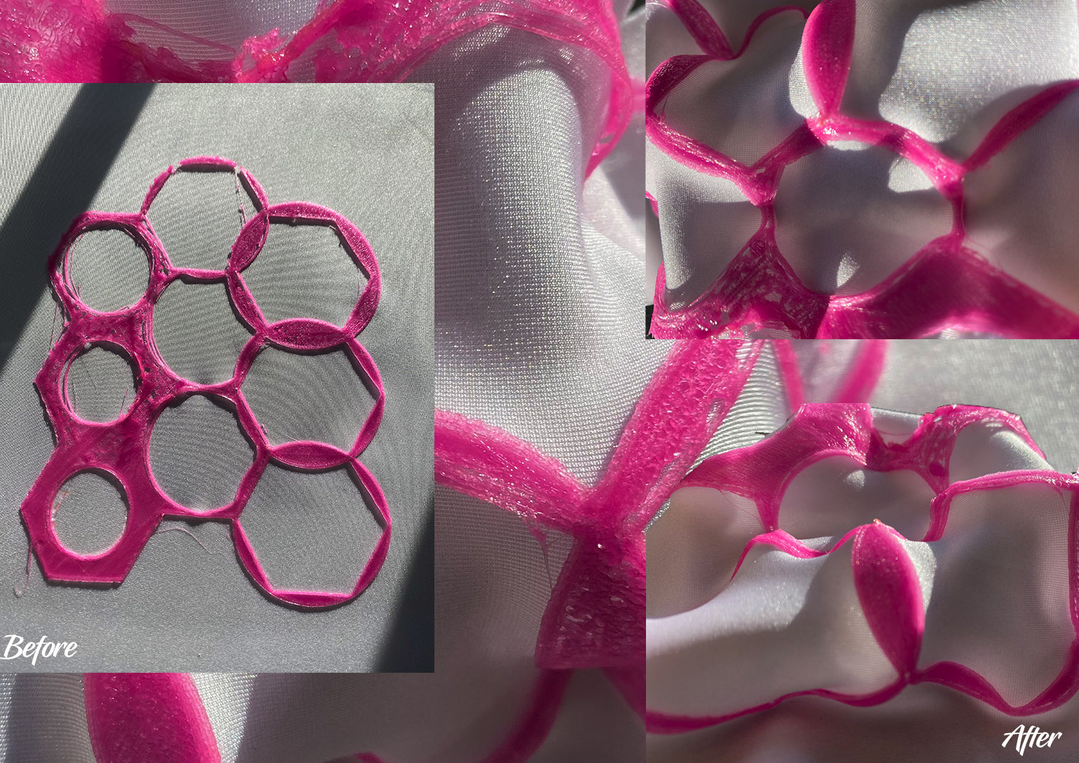
3D printed result: