13. Skin Electronics
For this assignment i’m literally face to face to electronics again, but this time, it was not so bad as i expected.
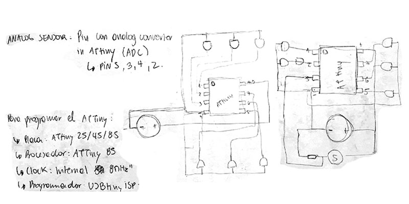
As always, the first step of any project for me it’s to make a little sketch,
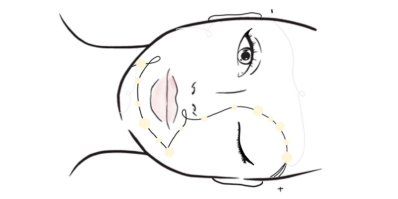
The idea it’s to make a GLOWING PEARL MAKE UP, where the pearls consist in half silicon sphere and inside there’s a LED to add this special glow that we need.
Materials
- EcoFlex Silicone
- 6 LED lights
- Black and White wires
- ATtiny
- Battery
- Digital Sensor (Same that i made for e-textiles)
- Resistance
Let’s made our pearls!
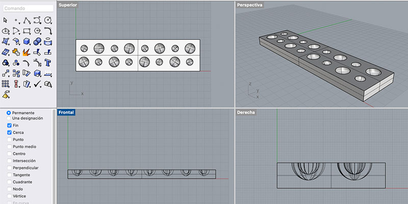
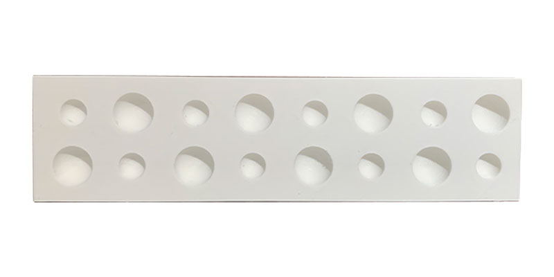
For the half silicon spheres, i printed a mold where to pour the silicon and put the LEDs on it, so they get encapsulated into the silicon and create “the pearls fantasy”
Flo v/s Electronics PT.03
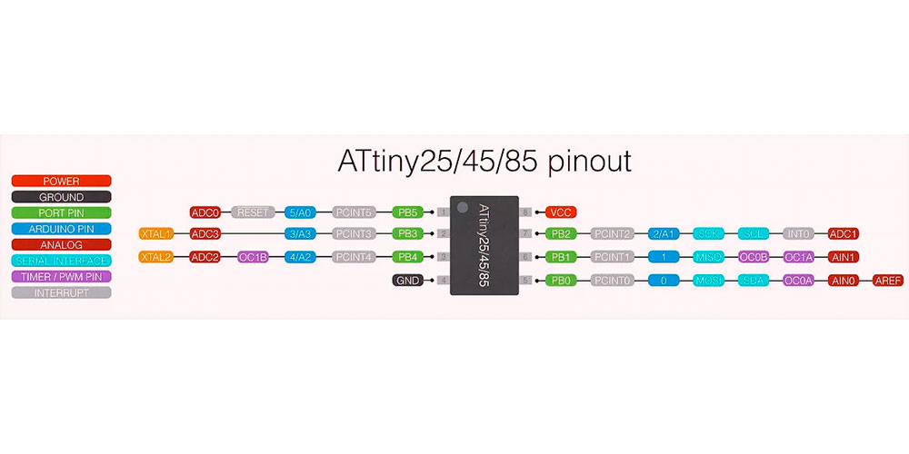
This time, we use Attiny to bring this project to life. The Attiny, a small microcontroller, with which we can carry out small projects, in which we do not need a large amount of memory or inputs or outputs. Programming of this micro can be done with Arduino.
So let the magic happen!
STEP 01: First things first, as always, to understand the process, i decided to made a connections sketch.
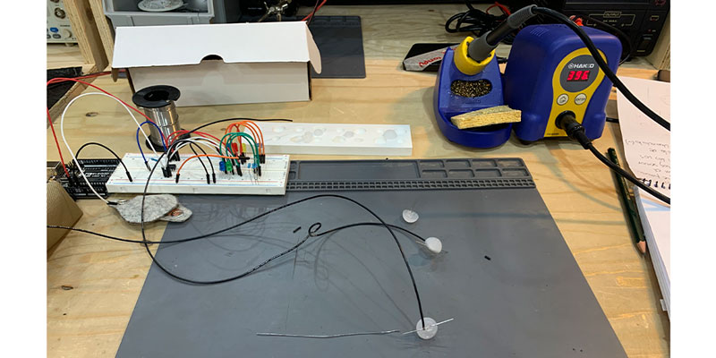
STEP 02: Once we have the idea, let’s start building the circuit!
Part 01:
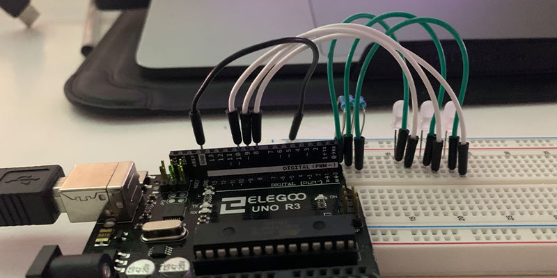
First I started with the AnalogReadSerial example in Arduino, just to make me comfortable with the circuits.
It works!!
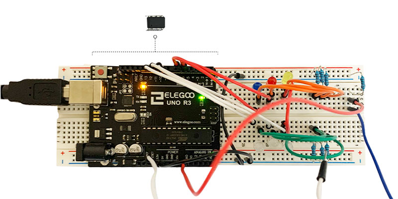
Part 02:
I decided to be daring (haha) and add more LEDs to the circuit (The six leds that i finally need for the make up)
The idea is to have the LEDs connected in a parallel circuit to turn on each of the lights in different times, some of them with faded and the others not.
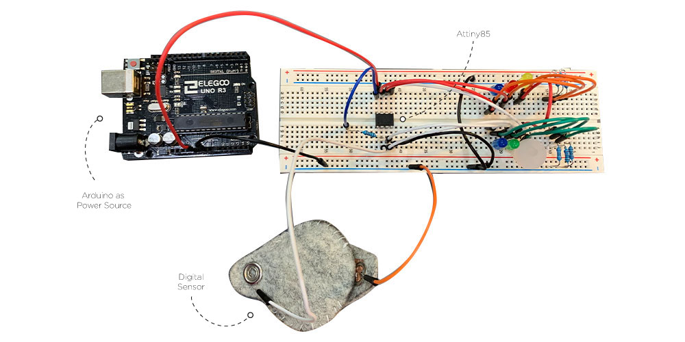
Part 03: Let's try the Faded
For this part, i need a analog sensor for the faded to make it work, so i use a peace of Velostate that we have in the lab.
STEP 03: So, now that i have my circuit working in Arduino with this code,
int lecture;

int pinLED1 = 11;
int pinLED2 = 10;
int pinLED3 = 9;
int pinLED4 = 9;
int pinLED5 = 6;
int pinLED6 = 5;

void setup() {

  pinMode(A0, INPUT);
  pinMode(pinLED1, OUTPUT);
  pinMode(pinLED2, OUTPUT);
  pinMode(pinLED3, OUTPUT);
  pinMode(pinLED4, OUTPUT);
  pinMode(pinLED5, OUTPUT);
  pinMode(pinLED6, OUTPUT);

}

void loop() {

  lecture = analogRead(A0);
  map(lecture, 0, 1023, 0, 255);

  analogWrite(pinLED1, lecture); // enciende
  analogWrite(pinLED2, LOW); // apaga
  analogWrite(pinLED3, LOW); // apaga
  analogWrite(pinLED4, LOW);
  analogWrite(pinLED5, LOW);
  analogWrite(pinLED6, LOW);

  analogWrite(pinLED1, lecture); // enciende
  analogWrite(pinLED2, LOW); // apaga
  analogWrite(pinLED3, LOW); // apaga
  analogWrite(pinLED4, LOW);
  analogWrite(pinLED5, LOW);
  analogWrite(pinLED6, LOW);

  delay(1000);

  analogWrite(pinLED1, LOW);
  analogWrite(pinLED2, lecture);
  analogWrite(pinLED3, LOW);
  analogWrite(pinLED4, LOW);
  analogWrite(pinLED5, LOW);
  analogWrite(pinLED6, LOW);

  delay(1000);

  analogWrite(pinLED1, LOW);
  analogWrite(pinLED2, LOW);
  analogWrite(pinLED3, lecture);
  //analogWrite(pinLED4, lecture);
  analogWrite(pinLED5, LOW);
  analogWrite(pinLED6, LOW);

  delay(1000);

  analogWrite(pinLED1, LOW);
  analogWrite(pinLED2, LOW);
  analogWrite(pinLED3, LOW);
  analogWrite(pinLED4, LOW);
  analogWrite(pinLED5, lecture);
  analogWrite(pinLED6, LOW);

  delay(1000);

  analogWrite(pinLED1, LOW);
  analogWrite(pinLED2, LOW);
  analogWrite(pinLED3, LOW);
  analogWrite(pinLED4, LOW);
  analogWrite(pinLED5, LOW);
  analogWrite(pinLED6, lecture);

  delay(1000);
}
i have to put all of this information in an Attiny format code.
STEP 04: Turn the Arduino code into an Attiny code, for this i need the for this I had to ask our guardian angel Josep for help, finally we figured out how to make the Attiny code.
int lecture;

int state = 1;

int delayTime = 2000;

int fade = 0;
int fadeSpeed = 20;
int fadeDirection = 1;

unsigned long previousTime;

int pinLED12 = 4;
int pinLED34 = 0;
int pinLED5 = 1;
int pinLED6 = 2;

void setup() {

  pinMode(3, INPUT);
  pinMode(pinLED12, OUTPUT);
  pinMode(pinLED34, OUTPUT);
  pinMode(pinLED5, OUTPUT);
  pinMode(pinLED6, OUTPUT);

}

void loop() {

  unsigned long startTime = millis();

  if (startTime - previousTime > delayTime){
    state = state + 1;
    previousTime = startTime;
  }


  if (state == 0){
    analogWrite(pinLED12, LOW); // enciende
    analogWrite(pinLED34, LOW); // apaga
    analogWrite(pinLED5, LOW);
    analogWrite(pinLED6, LOW);
  }
  else if (state == 1){
    analogWrite(pinLED12, fade); // enciende
    analogWrite(pinLED34, LOW); // apaga
    analogWrite(pinLED5, LOW);
    analogWrite(pinLED6, LOW);
  }
  else if (state == 2){
    analogWrite(pinLED12, LOW); // enciende
    analogWrite(pinLED34, fade); // apaga
    analogWrite(pinLED5, LOW);
    analogWrite(pinLED6, LOW);
  }
  else if (state == 3){
    analogWrite(pinLED12, LOW); // enciende
    analogWrite(pinLED34, LOW); // apaga
    analogWrite(pinLED5, fade);
    analogWrite(pinLED6, LOW);
  }
  else if (state == 4){
    analogWrite(pinLED12, LOW); // enciende
    analogWrite(pinLED34, LOW); // apaga
    analogWrite(pinLED5, LOW);
    analogWrite(pinLED6, fade);
  }
  else {
    state = 0;
  }

  if (digitalRead(3)) {
    fadeSpeed = 10 * fadeDirection;
  }
  else{
    fadeSpeed = 50 * fadeDirection;
  }

  delay(100);

  fade = fade + fadeSpeed;
  if (fade > 255) {
    fade = 255;
    fadeDirection = -1;
  }
  else if (fade < 0) {
    fade = 0;
    fadeDirection = 1;
  }

}
STEP 05: Once we have the electronics part working, i need to pass the circuit from the breadboard to the wires that i supposed to put into my face.
And as always, i have some problems with taking photos of the process when i'm deep concentrate on something, so i forgot to take pics of the circuits process, so sorry :(
Final Results
Thanks for reading! :)