XIII. | SKIN ELECTRONICS

| INSPIRATION |

WHY WE BLUSH?
Blushing is understood to be universal among humans, as well as exclusive to our species. Described by Charles Darwin as “the most peculiar and most human of all expressions,” in 1872, the phenomenon of blushing is still not fully understood by scientists. In his paper titled ‘The Puzzle of Blushing,’ Professor Ray Crozier, a Fellow of the British Psychological Society, called blushing a “ubiquitous yet little-understood phenomenon” that is both involuntary and uncontrollable. “An actor might simulate a smile, laughter or a frown, but not a blush,” he said.

Many psychologists believe that this suggests that blushing is a defense mechanism, a response we developed to help avoid a potential fight-or-flight confrontation. I have violated a social code.
- Devrupa Rakshit, The Science Behind Why We Blush, 2020
- Lisa Feldman Barett, How Emotions Are Made, 2017
- Fabtextiles, Thermochromic research, 2018
- Filipe Magalhaes, Chromatact, 2021
| ELECTRONICS - COMPONENTS |
ATtiny
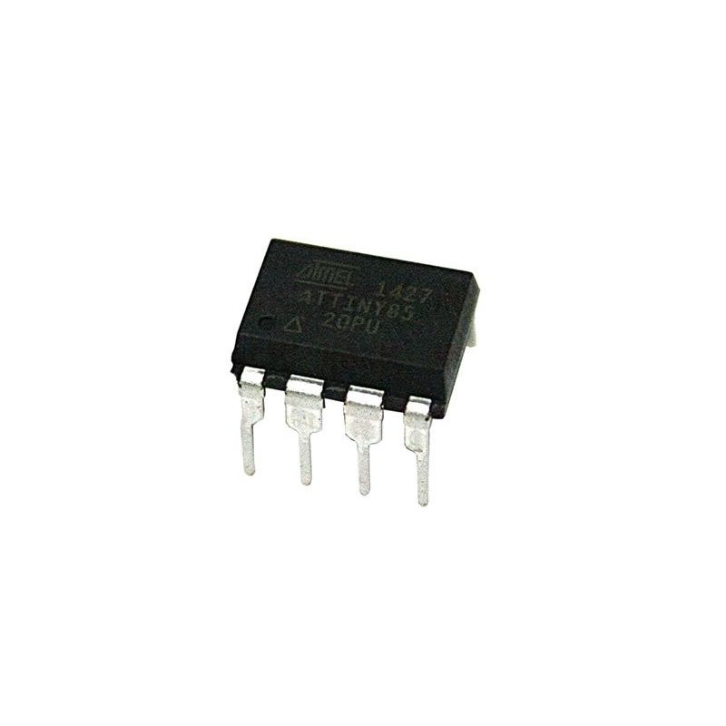
- Microcontroller ATtiny85
ATtiny85 microcontroller is one of the small and high-performance AVR microcontroller, which is based on RISC CPU. It is one of the 8-pin microcontrollers that comes in two packages, used to control and interfacing between different devices and sensors.
REFERENCES
- Arduino - Attiny installation
- Arduino - code
- Mark Olson's Lab & Tutorial Repo
- Tracking Watch
- Tracking Watch
- Filipe Magalhaes, Chromatact, 2021
ATtiny85 Breakout Board
- ATtiny85 Breakout Board
This ATtiny85 Breakout Board is THE SMALLEST Arduino-compatible board measuring less that 1 square inch.
FIBER OPTICS

LUMINOUS FIBER OPTICS FABRIC
-
Description: The Fiber Optics Fabric is made of ultra-thin optical fibers, directly woven with synthetic fibers. The optical fibers are specially processed in order to allow the light to be emitted along the full length of the fibers (side emitting fibers). The optical fibers are then connected to ultra-bright LEDs (embedded in borders at the edge of the fabric), which inject light into the fabric. The Fiber Optics Fabric is available in a dozen of colors. It is water resistant and can be washed.
- Wearable Fiber Optic Technology Based on Smart Textile
REFERENCES
- Fiber Optic Poetry
- Color Changing Fiber Optic Fabric
- Fabricademy, Recommended
- How to Connect Optical Fibers to LEDs
| ANALOG SENSOR / PRESSURE |
- You can use a soft sensor from Week 05 - E-Textiles
- Or you will need velostat, tape and conductive thread - easy and dirty version to test your prototype.
REFERENCES
| PROGRAMMING |
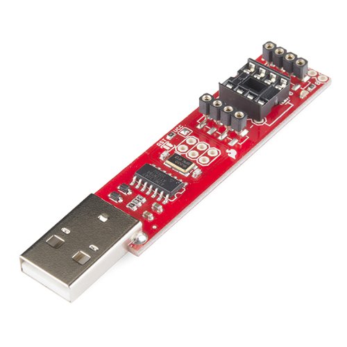
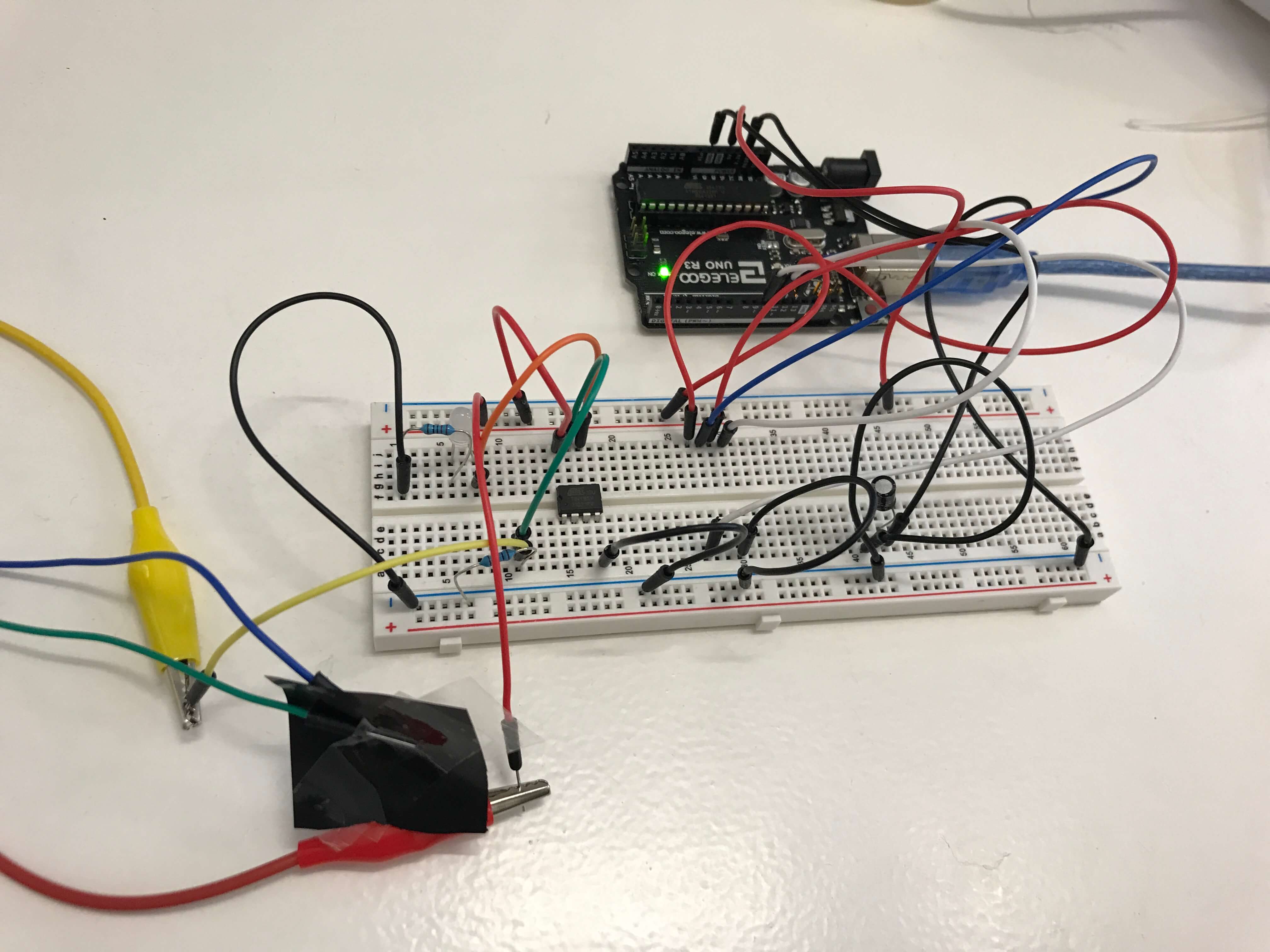
You can use the Arduino UNO or Tiny AVR Programmer (picture below)) which should be easier to program your ATtiny.
HOW TO PROGRAM ATtiny using ARDUINO
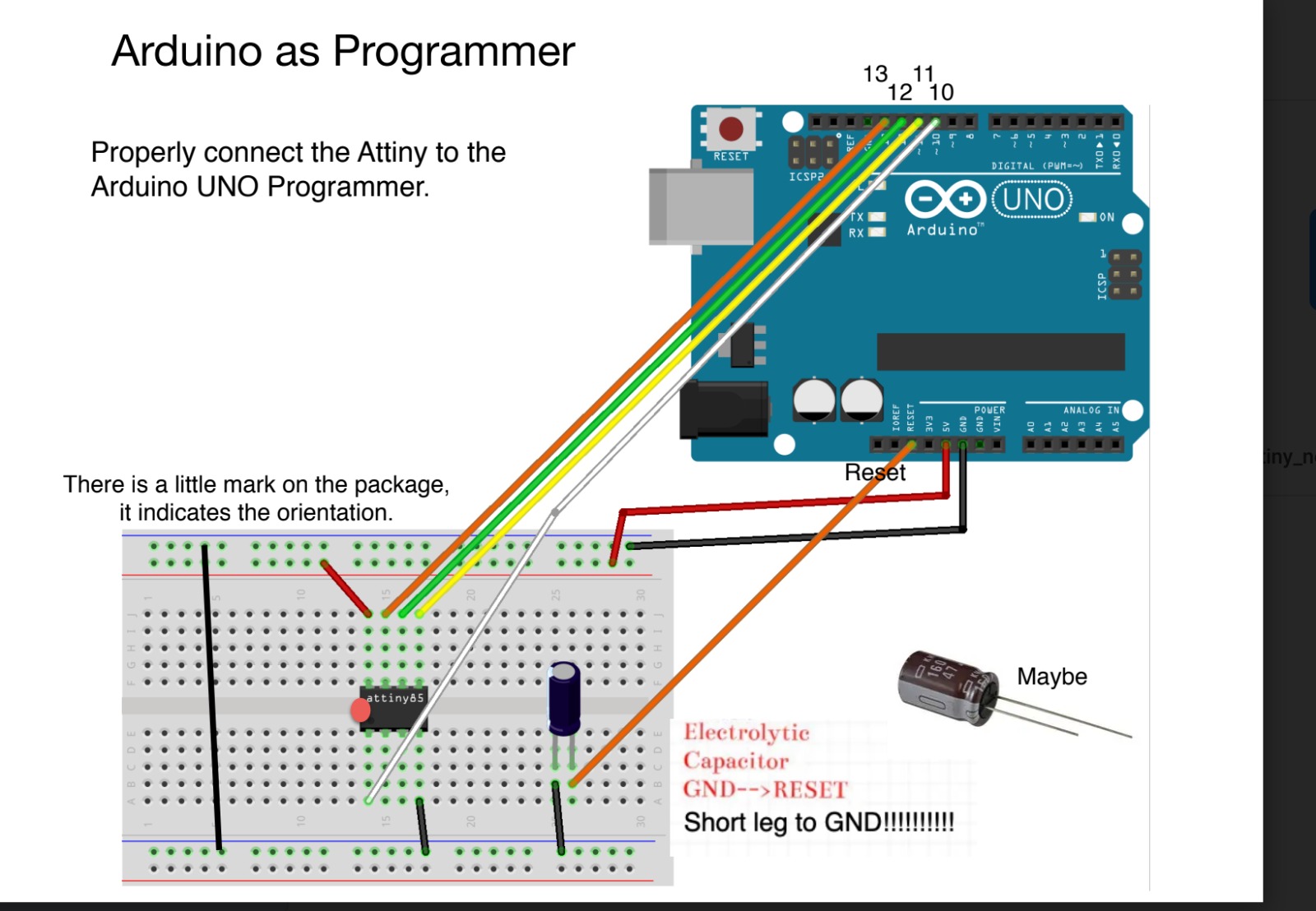
-
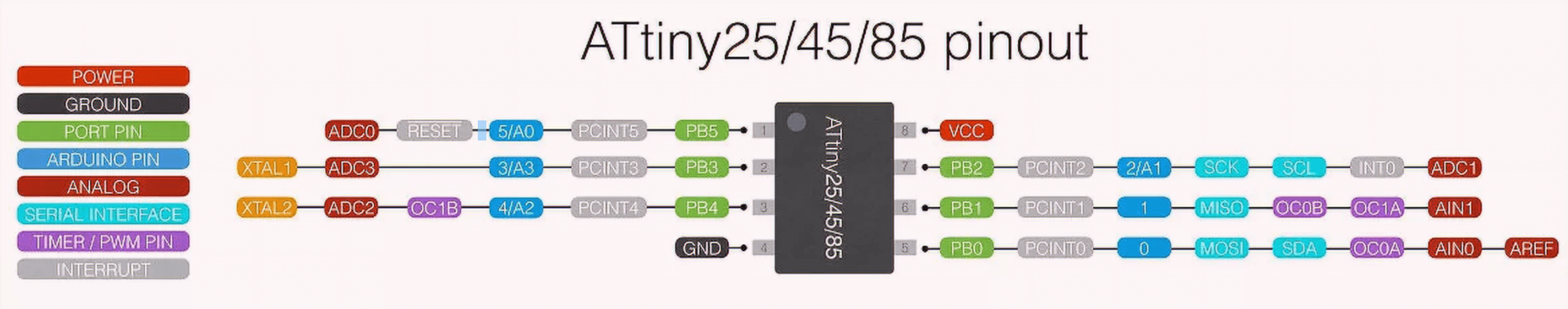
In the picture above you can see 8 pins of ATtiny, which are different from the pins of Arduino - in this case they must be written differently in the code. For this reason, we need to program ATtiny using Arduino as a programmer.
- How to Program an ATtiny with Arduino
- Programming ATtiny85 with Arduino Uno
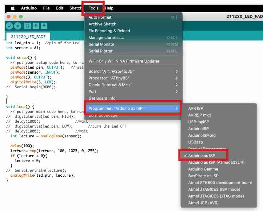
TOOLS SET UP
Arduino programming
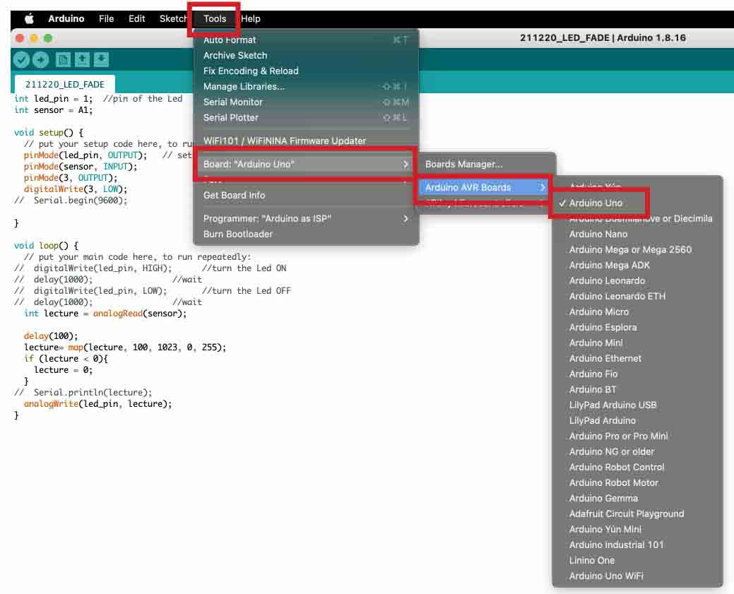
- TOOLS -> Programmer: Arduino as ISP
- TOOLS -> Board: Arduino UNO
- TOOLS -> Clock: Internal 8 Mhz
- TOOLS -> Burn Bootloader - Use this option you can check out if your code is correct before you will burn your ATtiny.
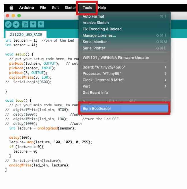
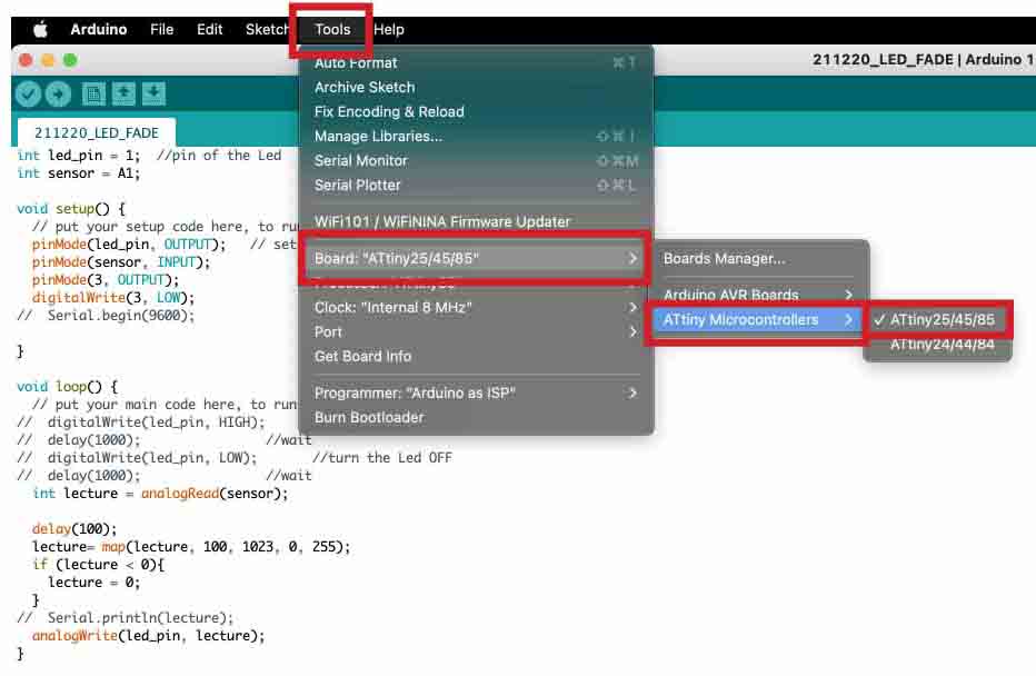
Sending the code to ATtiny
- TOOLS -> Programmer: Arduino as ISP
- TOOLS -> Board: ATtiny 25/45/85
- TOOLS -> Processor: ATtiny 85
- TOOLS -> Clock: Internal 8 Mhz
LED FADING
- First, we used Blink code as a test to program ATtiny.
/* Emma Pareschi, Nov 2019
 *
 *  the led connected to pin 1. it blinks
*/

int led_pin = 1;  //pin of the Led

void setup() {
  // put your setup code here, to run once:
  pinMode(led_pin, OUTPUT);   // set the pin 3 as OUTPUT

}

void loop() {
  // put your main code here, to run repeatedly:
  digitalWrite(led_pin, HIGH);      //turn the Led ON
  delay(1000);                //wait
  digitalWrite(led_pin, LOW);       //turn the Led OFF
  delay(1000);                //wait
}
ARDUINO - LED FADING + SENSOR
- Then we added a pressure sensor and a fiber optic LED.
int led_pin = 1;  //pin of the Led
int sensor = A1;

void setup() {
  // put your setup code here, to run once:
  pinMode(led_pin, OUTPUT);   // set the pin 3 as OUTPUT
  pinMode(sensor, INPUT);
  pinMode(3, OUTPUT);
  digitalWrite(3, LOW);
//  Serial.begin(9600);

}

void loop() {
  // put your main code here, to run repeatedly:
//  digitalWrite(led_pin, HIGH);      //turn the Led ON
//  delay(1000);                //wait
//  digitalWrite(led_pin, LOW);       //turn the Led OFF
//  delay(1000);                //wait
  int lecture = analogRead(sensor);

  delay(100);
  lecture= map(lecture, 100, 1023, 0, 255);
  if (lecture < 0){
    lecture = 0;
  }
//  Serial.println(lecture);
  analogWrite(led_pin, lecture);
}
PROCESS
SKIN ELECTRONICS WEEK 13 from PETRA GARAJOVÁ on Vimeo.
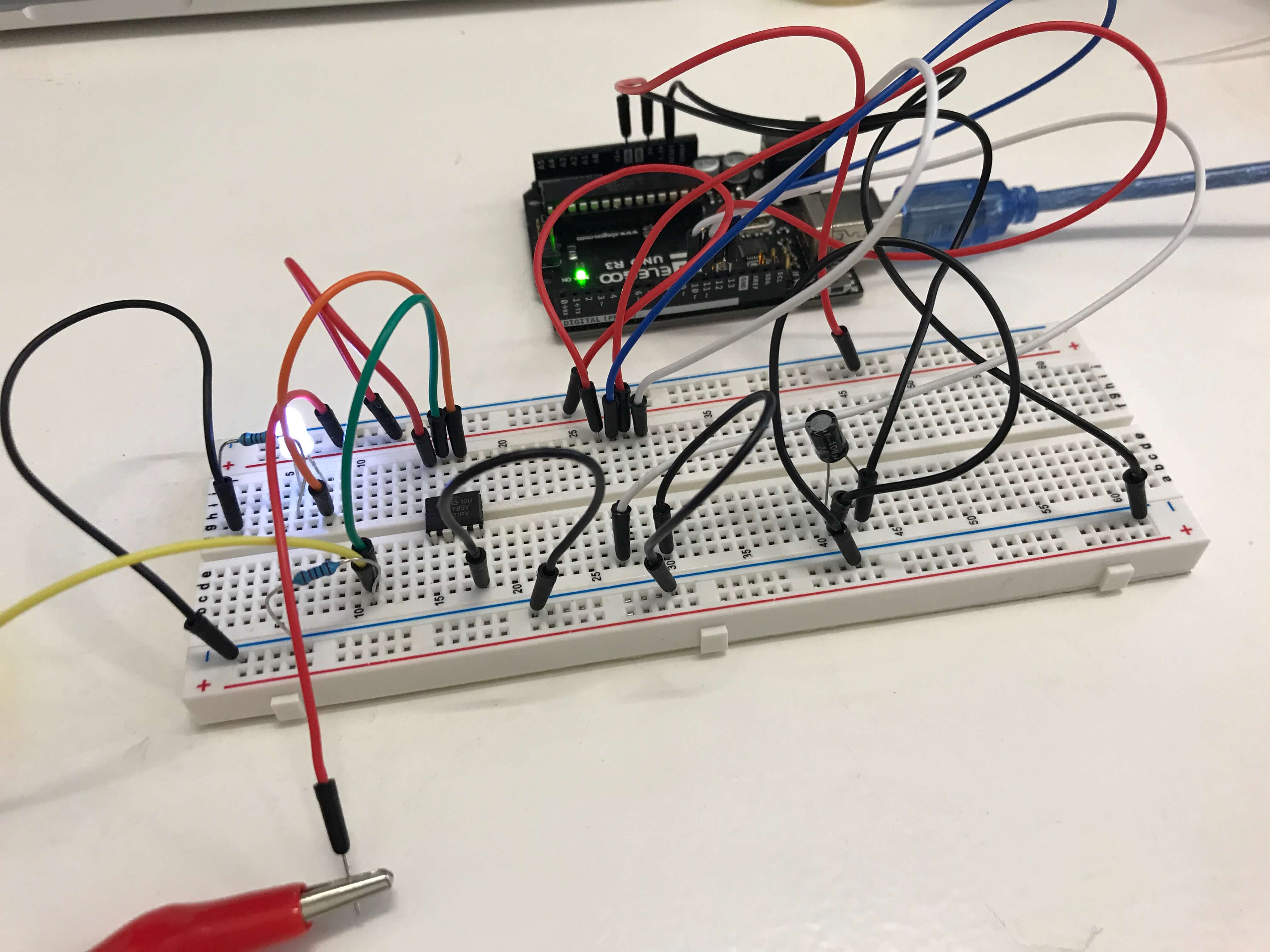
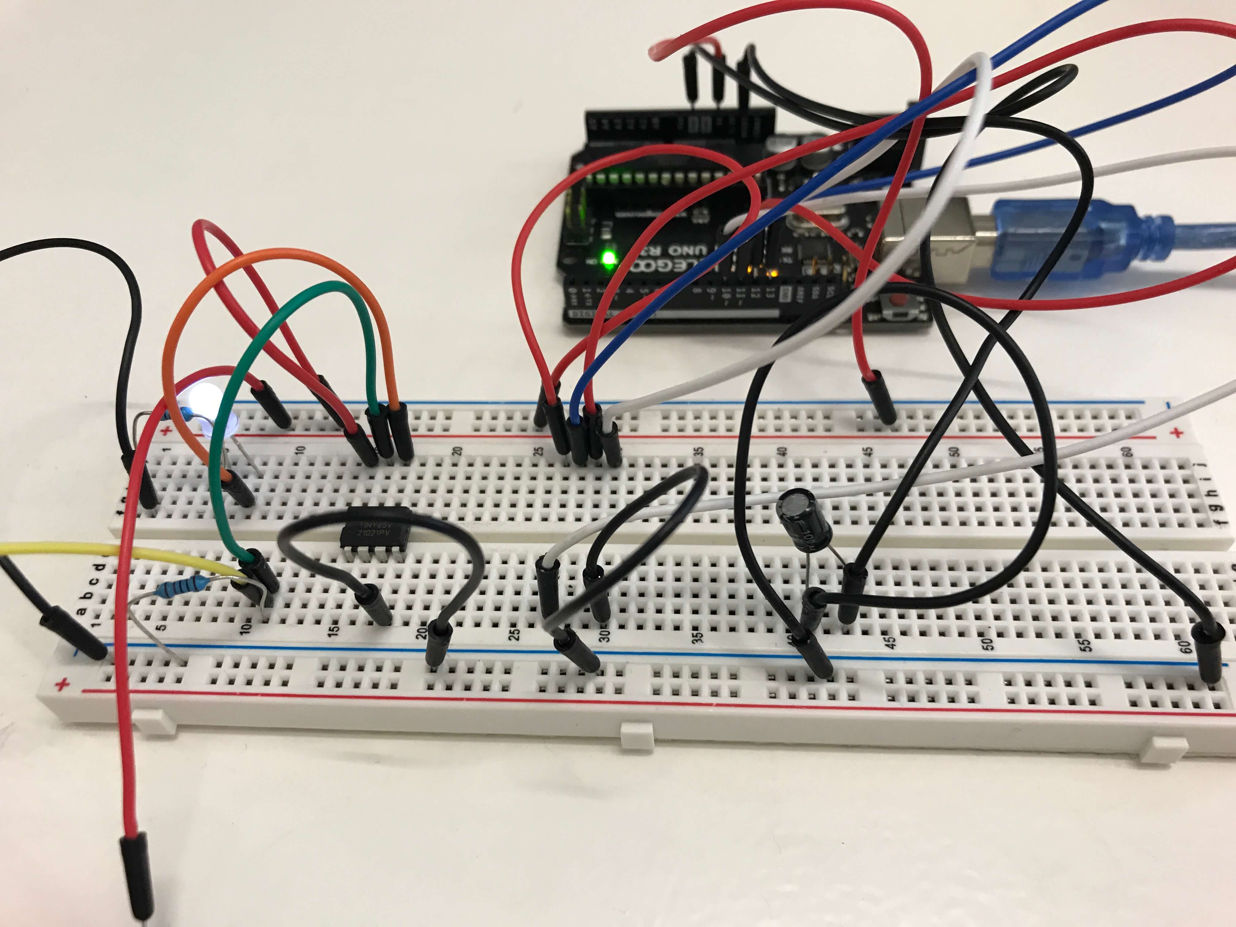
ATtiny & SENSOR
ATtiny85 Breakout Board - LED FADING + SENSOR
COMPONENTS
| N. | Material name | Quantity | Source |
|---|---|---|---|
| 1. | Arduino UNO | 1 | UNO R3 Kit |
| 2. | ATtiny Microcontroller 85 | 1 | Fab Lab BCN |
| 3. | ATtiny 85 Breakout Board | 1 | Fab Lab BCN |
| 4. | Battery 3 V | 1 | Fab Lab BCN |
| 5. | Battery holder | 1 | Fab Lab BCN |
| 6. | Capacitor | 1 | UNO R3 Kit |
| 7. | Breadboard | 1 | UNO R3 Kit |
| 8. | LED light | 1 | UNO R3 Kit |
| 9. | Optic fiber 4 mm | 1 | Fab Lab BCN |
| 10. | Velostat | small piece | Fab Lab BCN |
| 11. | Resistor 220Ω | 1 | UNO R3 Kit |
| 12. | Resistor 10KΩ | 1 | UNO R3 Kit |
| 13. | Crocodiles | 2 | Fab Lab BCN |
| 14. | Plastic tape | - | Fab Lab BCN |
| 15. | USB cable | 1 | UNO R3 Kit |
| 16. | Jumpers | 30 | UNO R3 Kit |
PROCESS
- Our ATtiny Breakout Board has different types of pins, so we had to change regarding to the new disposition.
- The LED light also needs to be prepared and glued or connected to the optical fiber using a plastic tube for example.
- Connect 3V battery to the battery holder and solder it with the red and black wire.
- You will have to solder the sensor wires as well with the correct Attiny pins.
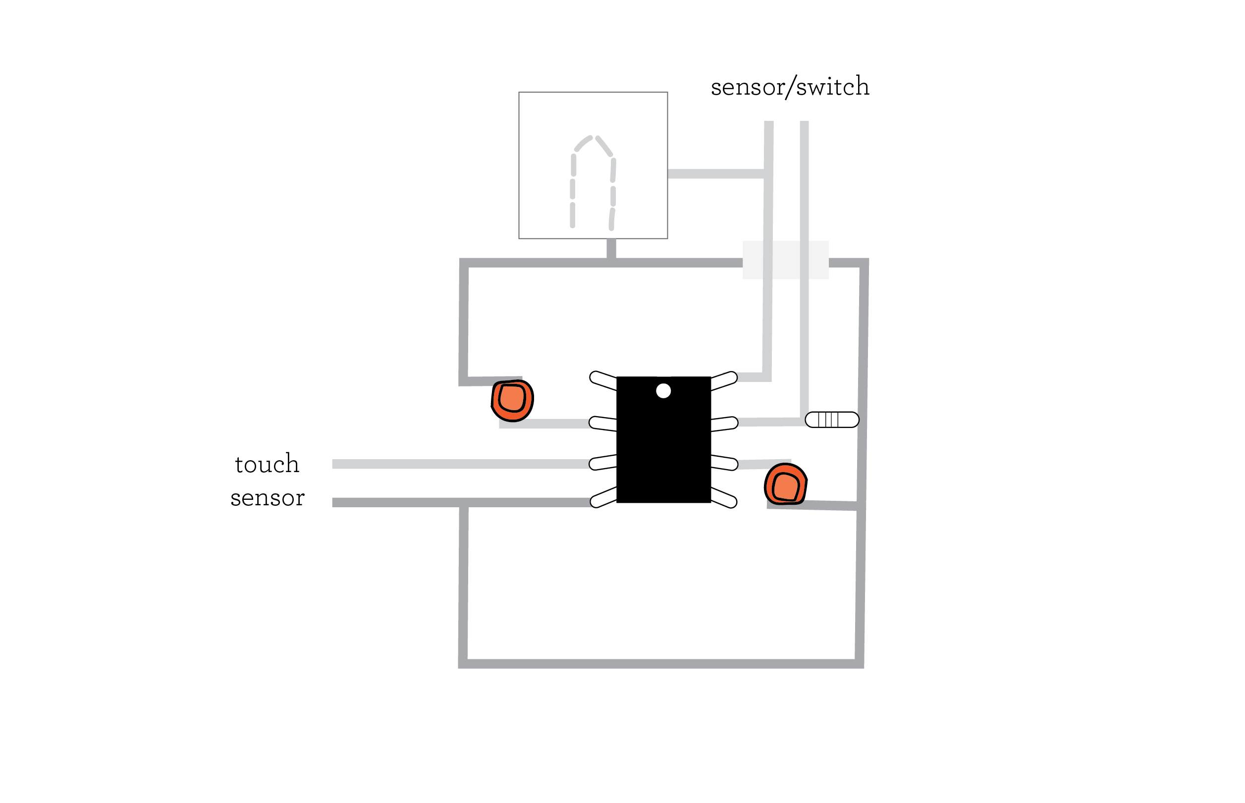
CODE
- GND - Pin 3 and 4
- LED - Pin 1
- SENSOR - Pin 2
int led_pin = 1;  //pin of the Led
int sensor = A1;

void setup() {
  // put your setup code here, to run once:
  pinMode(led_pin, OUTPUT);   // set the pin 3 as OUTPUT
  pinMode(sensor, INPUT);
  pinMode(3, OUTPUT);
  digitalWrite(3, LOW);
  pinMode(4, OUTPUT);
  digitalWrite(4, LOW);
//  Serial.begin(9600);

}

void loop() {
  // put your main code here, to run repeatedly:
//  digitalWrite(led_pin, HIGH);      //turn the Led ON
//  delay(1000);                //wait
//  digitalWrite(led_pin, LOW);       //turn the Led OFF
//  delay(1000);                //wait
  int lecture = analogRead(sensor);

  delay(100);
  lecture= map(lecture, 100, 1023, 0, 255);
  if (lecture < 0){
    lecture = 0;
  }
//  Serial.println(lecture);
  analogWrite(led_pin, lecture);
}
RESULT
SKIN ELECTRONICS WEEK 13 from PETRA GARAJOVÁ on Vimeo.
SKIN ELECTRONICS WEEK 13 from PETRA GARAJOVÁ on Vimeo.
REFERENCES
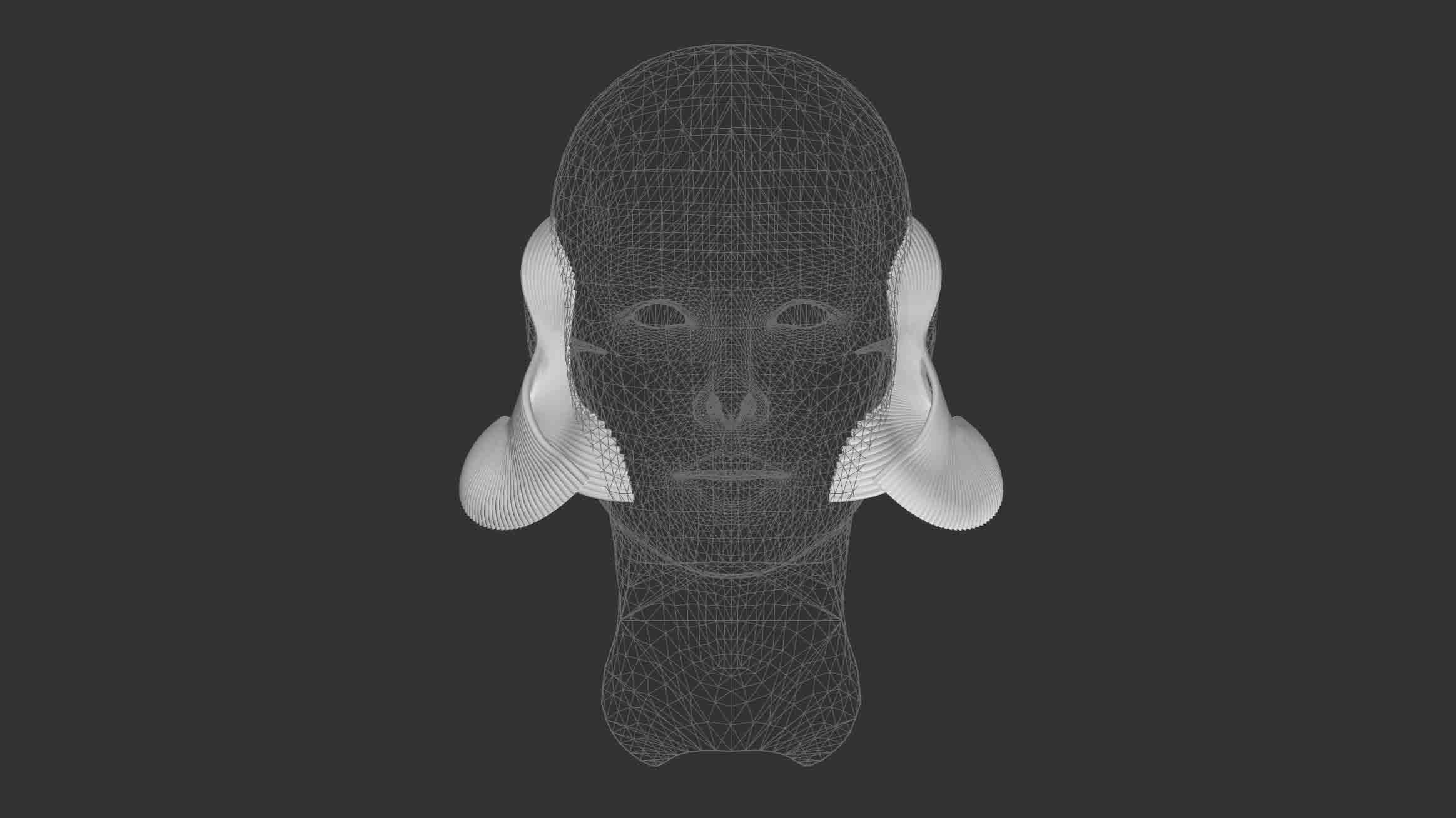
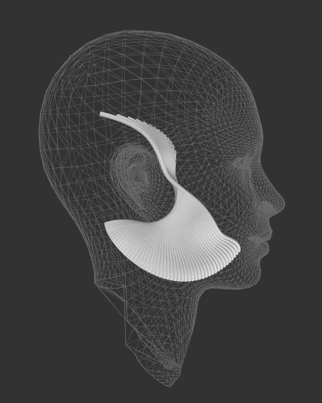
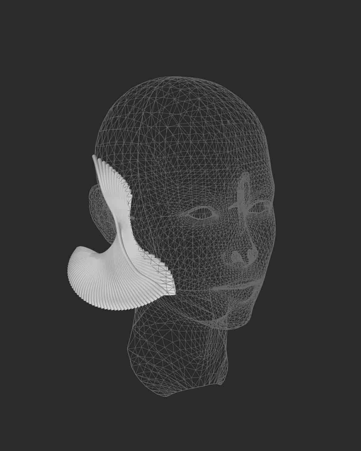
| DISPLAY OF EMOTION |
3D PRINTED PROPOSAL - FLEX
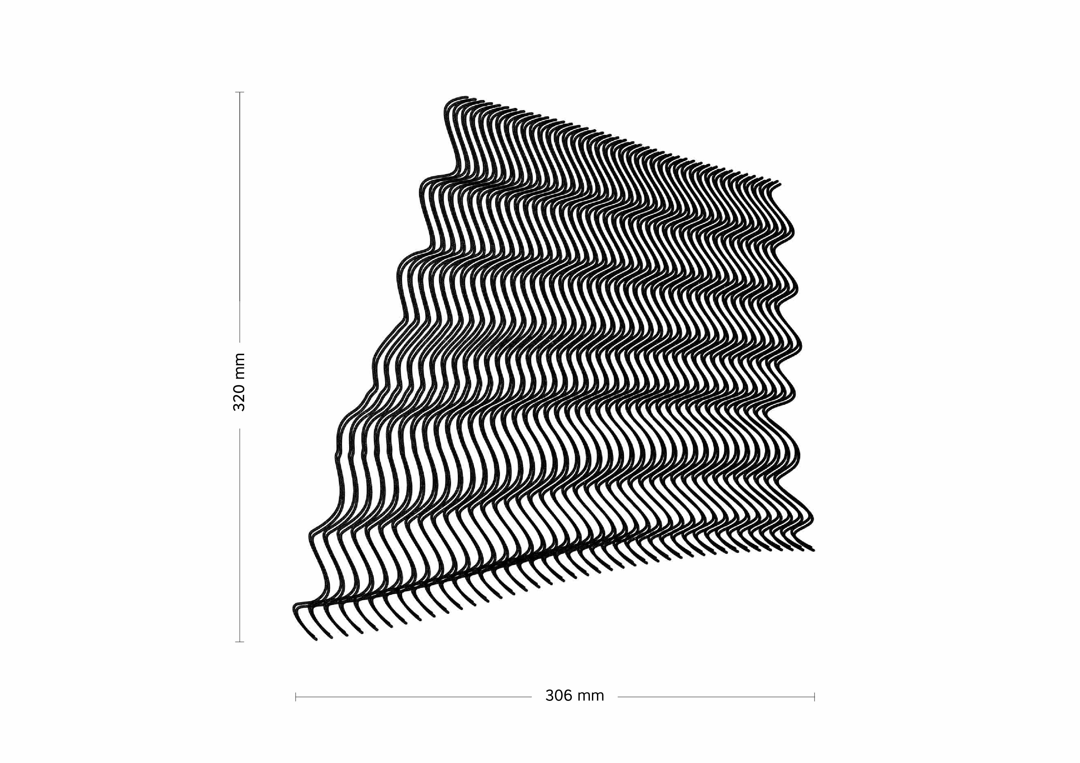
RESULT
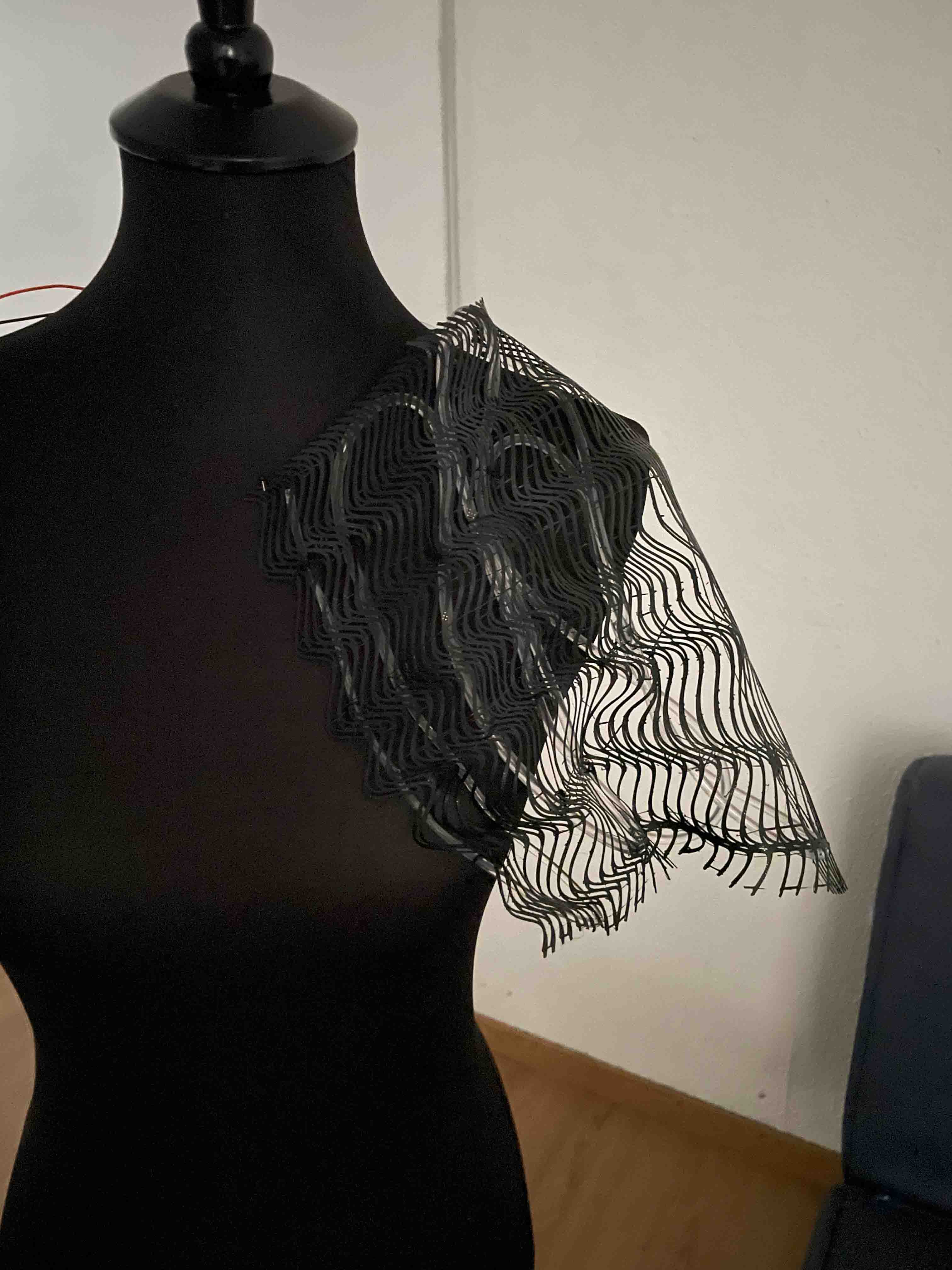
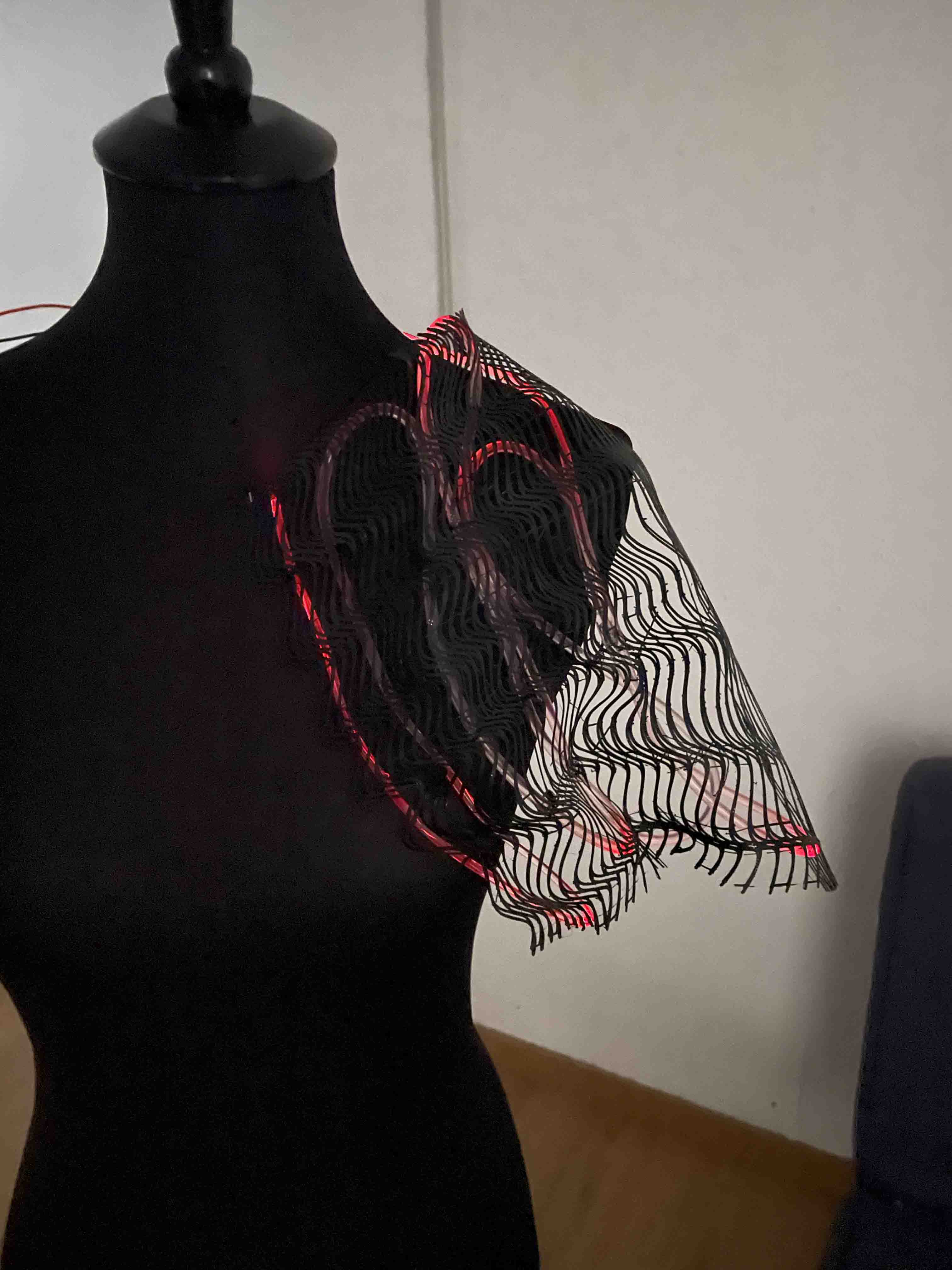
CONCLUSION
The 3D printed object (flex filament) was not strong enough for this type of fiber optics (4 mm thick) and slightly deformed the shape. Thinner optical fibers will better follow the curves of 3D printing.
3D PRINTED PROPOSAL - PLA