Week 13 | Skin Electronics
Inspiration
My inspiration for this week isn't about a direct skin electronic application, but the self-powering abilities of Electric Skin, a material research project that is about crafting a new self-powering biomaterials with bacteria. Catherine Euale, who came to visit us for biochomes and biomaterials week is the material specialist in this research. Below is a beatiful video highlighting the project goals and current proof of concept.
ATtiny
An ATtiny is a mini Aurdino that can be programed and connected with a small battery to power different circuits and systems. To set up using an ATtiny with Arudino this Instructables explains it pretty well as does Emma's lecture. Once set up you'll have a micro controller to program.
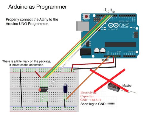
Setup
- Connect the Attiny to your Programmer: - AVR programmer - Arduino UNO (make sure that the Arduino is uploaded with the ARduinoISP sketch)
- In Arduino IDE: Select board (attiny85 (internal 8MHz)) and port
- In Arduino IDE: Select programmer, Arduino as ISP or USBtinyISP
- In Arduino IDE: For first time set up of the Attiny =>Burn the bootloader
- On Breadboard: connect the Attiny to your input/output devices
- In Arduino IDE: Upload the code to the Attiny through Arduino
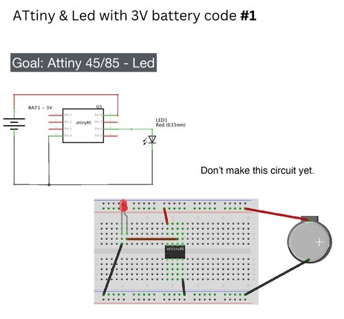
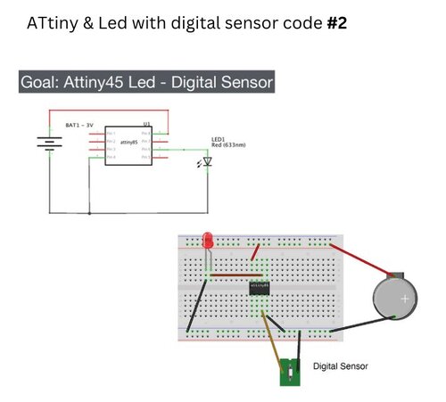
To practice and understand how to get an LED and Nano pixel set up with the ATtiny we did these exercises and cicuits below:
Digital Sensor & LED 1
    /* Emma Pareschi, Nov 2019
    *
    *  the led connected to pin 1. it blinks
    */

    int led_pin = 1;  //pin of the Led

    void setup() {
    // put your setup code here, to run once:
    pinMode(led_pin, OUTPUT);   // set the pin 1 as OUTPUT

    }

    void loop() {
    // put your main code here, to run repeatedly:
    digitalWrite(led_pin, HIGH);      //turn the Led ON
    delay(1000);                //wait
    digitalWrite(led_pin, LOW);       //turn the Led OFF
    delay(1000);                //wait
    }
Digital Sensor & LED 2
    /*
    Emma Pareschi 2020
    the Led turns on when the digital sensor is triggered
    */

    // this constant won't change:
    int sw_pin = 4;    // the pin that the pushbutton is attached to

    int led_pin = 1; //pin of the led

    // Variables will change:
    int sw_status = 0;         // current state of the button

    void setup() {
    // initialize input and output pins:
    pinMode(sw_pin, INPUT_PULLUP);
    pinMode(led_pin, OUTPUT);

    }

    void loop() {

    // read the pushbutton input pin:
    sw_status = digitalRead(sw_pin);

    // compare the switch status to its previous state
    if (sw_status == LOW) {   //if the sw is pressed
        digitalWrite(led_pin, HIGH);   //turn on the led (5V)
    } else {        //if the sw is not pressed
        digitalWrite(led_pin, LOW);   //turn off the Led (0V)
    }

    }
Digital Sensor & NanoPixel
    #include <Adafruit_NeoPixel.h>
    // A basic everyday NeoPixel strip test program.

    // NEOPIXEL BEST PRACTICES for most reliable operation:
    // - Add 1000 uF CAPACITOR between NeoPixel strip's + and - connections.
    // - MINIMIZE WIRING LENGTH between microcontroller board and first pixel.
    // - NeoPixel strip's DATA-IN should pass through a 300-500 OHM RESISTOR.
    // - AVOID connecting NeoPixels on a LIVE CIRCUIT. If you must, ALWAYS
    //   connect GROUND (-) first, then +, then data.
    // - When using a 3.3V microcontroller with a 5V-powered NeoPixel strip,
    //   a LOGIC-LEVEL CONVERTER on the data line is STRONGLY RECOMMENDED.
    // (Skipping these may work OK on your workbench but can fail in the field)

    // Which pin on the Arduino is connected to the NeoPixels?
    // On a Trinket or Gemma we suggest changing this to 1:
    #define LED_PIN    1

    // How many NeoPixels are attached to the Arduino?
    #define LED_COUNT 8

    // Declare our NeoPixel strip object:
    Adafruit_NeoPixel strip(LED_COUNT, LED_PIN, NEO_GRB + NEO_KHZ800);
    // Argument 1 = Number of pixels in NeoPixel strip
    // Argument 2 = Arduino pin number (most are valid)
    // Argument 3 = Pixel type flags, add together as needed:
    //   NEO_KHZ800  800 KHz bitstream (most NeoPixel products w/WS2812 LEDs)
    //   NEO_KHZ400  400 KHz (classic 'v1' (not v2) FLORA pixels, WS2811 drivers)
    //   NEO_GRB     Pixels are wired for GRB bitstream (most NeoPixel products)
    //   NEO_RGB     Pixels are wired for RGB bitstream (v1 FLORA pixels, not v2)
    //   NEO_RGBW    Pixels are wired for RGBW bitstream (NeoPixel RGBW products)

    uint32_t off = strip.Color(0, 0, 0);

    int sw_pin = 2;
    int sw_status = 0;


    // setup() function -- runs once at startup --------------------------------

    void setup() {

    strip.begin();           // INITIALIZE NeoPixel strip object (REQUIRED)
    strip.show();            // Turn OFF all pixels ASAP
    strip.setBrightness(50); // Set BRIGHTNESS to about 1/5 (max = 255)

    pinMode(sw_pin, INPUT_PULLUP);

    }


    // loop() function -- runs repeatedly as long as board is on ---------------

    void loop() {

    sw_status = digitalRead(sw_pin);

    if (sw_status == 0){
        colorWipe(strip.Color(255,   0,   0), 50); // Red
        strip.fill(off, 0, 10);
        strip.show();  //display the color
        }
    }

    // Fill strip pixels one after another with a color. Strip is NOT cleared
    // first; anything there will be covered pixel by pixel. Pass in color
    // (as a single 'packed' 32-bit value, which you can get by calling
    // strip.Color(red, green, blue) as shown in the loop() function above),
    // and a delay time (in milliseconds) between pixels.
    void colorWipe(uint32_t color, int wait) {
    for(int i=0; i<strip.numPixels(); i++) { // For each pixel in strip...
        strip.setPixelColor(i, color);         //  Set pixel's color (in RAM)
        strip.show();                          //  Update strip to match
        delay(wait);                           //  Pause for a moment
    }
    }
BioMaterial Circuit
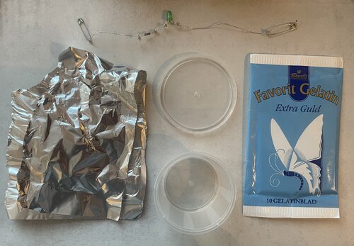
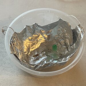
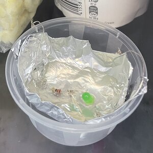
Taking inspiration from Electric Skin I referenced earlier I wanted to see how I could incorrperate a circuit into a bio material and later on a bio-pottery piece that would then be used as hair, nail, or jewelry accessories. Since I didn't have an ATtiny to make my bio-material I have made a circuit below of a digital sensor and LED that is embeded in gelatin with Aurdino. If I had had an ATtiny I would have made a sample with the circuit from Digital Sensor and LED 1 above.
Prototype
Materials
- 4g Gelatin
- 20ml H20
- Conductive thread
- Arduino Uno
- 1 220 Om resistor
- 1 LED
- 2 Safety Pins
- 2 Pin wires
- 2 Alligator Clips
- Stove top
- Freezer
Process
- Curl ends of LED and 220 Resistor making sure to take note as to which side leg of the LED is the long one
- Use conductive thread to sew the safety pin, leave a tail and then sew the resistor, leave another tail and sew/tie off to the long leg of the LED
- Use another piece of conductive thread to sew the safety pin, leave a tail and then sew/tie off to the short leg of the LED
- Test circuit with code below
- Melt gelatin in H20 in a pot on a stove top
- Prepare a mold to lay to the circuit into
- Pour the dissolved gelatin into the mold
- Put the mold into the freezer for 10 min
- Remove from freezer
- Test circuit
        void setup() {
    pinMode(12, OUTPUT);
    }

        void loop() {
    digitalWrite(12, HIGH);
    delay(2000);
    digitalWrite(12, LOW);
    delay(1000);

    }
So it worked to embed a circuit into a biomaterial! This give me a lot of ideas of how to incorperate circuits into my BioPottery forms. My main concerns are of how can the circuits be removed to be recycled and if they get hot at all if it will impact the biomaterial. But more to explore when I can get my hands on an ATtiny again to test and cast another form. It would also be fun to figure out what type of metal beads or other potential conductors could be incorperated.
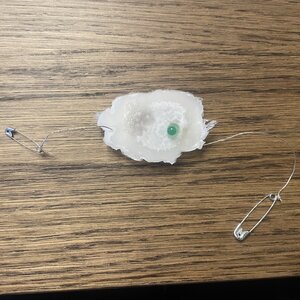
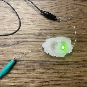
Circuit Dried Up
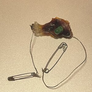
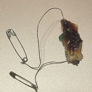
I was not expecting the circuit to become all rusted. It makes sense that it did. I just didn't think about it. Below is a video testing if it is still conductive.
As I said above about incorperating a circuit into biomaterials/bio-pottery would be interesting, however after seeing how this test dried I'll have to go back to the drawing board for multiple reason. It's great that it's still conductive even though it got rusty. However, the rust is problematic for doing next to skin wearables or pieces in general. However to get around the rusting could be testing it with different biomaterials that use less water. It would be interesting to see with an ATtiny or an even smaller microcontoller if sophisticated and small jewlery circuits could be designed in a bio material. But also to just have it incorperated into a bio-pottery sculpture would be super interesting and add another dimension to the function and/or interaction with a sculptural piece. Esspecially if the circuit is triggered by ceratin parameters like light, sound, humidity to name a few. I only worry though that the heat of the circuit could effect the biomaterial. And that it also makes the biomaterial not be recyclable. So there might need to be a design that allows main componets of the circuit to be protected so they don't rust and leach into the biomaterial so the overall piece can be dismanteled at some point.