5∙ E-textiles
18th to 25th October 2022
Update
- October, 2022
- Avril, 2023
Assignments
- Build at least one digital and one analogue soft sensor, using different materials and techniques.
- Document the sensor project as well as the readings got using the AnalogRead of Arduino
- Integrate the two soft sensors into one or two textile swatches using hard soft connections
- Document the circuit and its schematic
- Document your swatches / samples
- Upload your arduino code as text
- Upload a small video of the swatches functioning
- Integrate the swatch into a project (extra credit)
Ressources of the week
Research & Ideation
For this week our instructor is Liza Stark.
I'm really excited about this E-textiles week, I'm little bit obsessed about how is possible to make like a synthetizer with textile. And how is possible to ad some electronic with knitting and aswell how is possible make a ink for textile being connected. After the week of colors we saw some recipe with iron. Some idea I would like to make pieces of clothes in knitting with the possibilities to listening field record of the nature. And having a pattern transform in binary using this field.
References & Inspiration
My inspiration was floating arround electronic music, nature, knitting, conductive inks.
Irene Posh and Ebru Kurbak
Drapery FM project
Zoe Romano
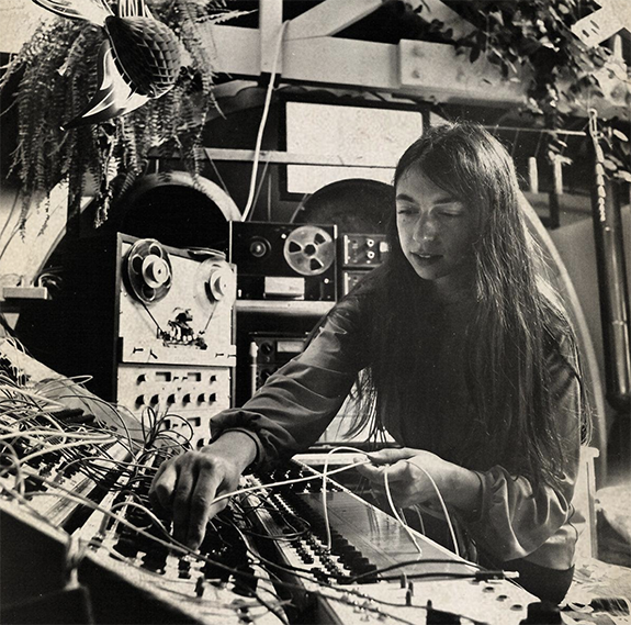
Suzanne Ciani
is an American musician, sound designer, composer, and record label executive who found early success in the 1970s with her electronic music and sound effects for films and television commercials. Her career has included works with quadraphonic sound. She almost use a Buchla, modular synthesizer.
The movie : Sisters with transistors
is a story of electronic music’s female pioneers, composers who embraced machines and their liberating technologies to utterly transform how we produce and listen to music today.
SISTERS WITH TRANSISTORS from Monoduo Films on Vimeo.
Neuro Knitting
The research of Maurin Donneaud
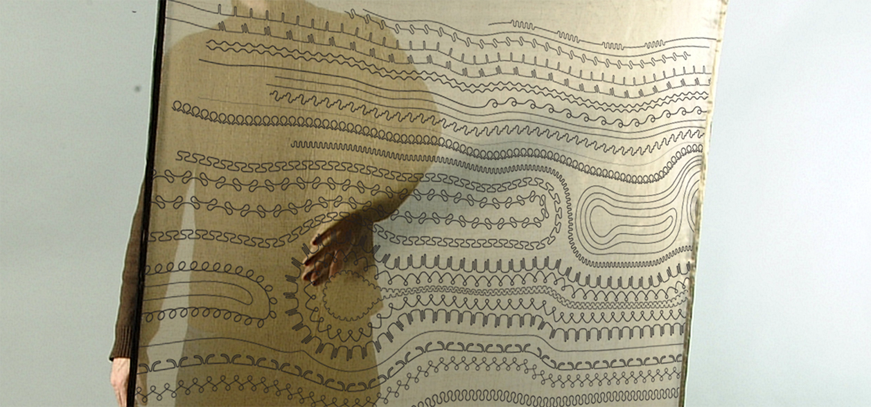
XY Textile image in the left
The XY-textile is a large textile interface use to compose and play electronic music. By its size, its texture, its flexibility and its transparency, this textile interface involves the whole body in the musical interpretation. Like a music score, the graphics represented on the fabric, give to the composer the ability to locate and play every sounds and sound controls. Source github
Synth on the right Source github
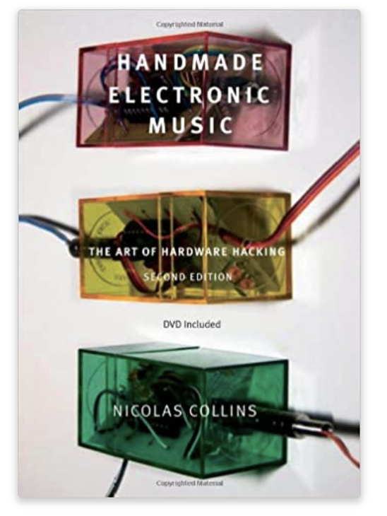
Nicolas Collins
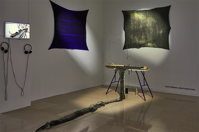
Claire Williams
Process and workflow
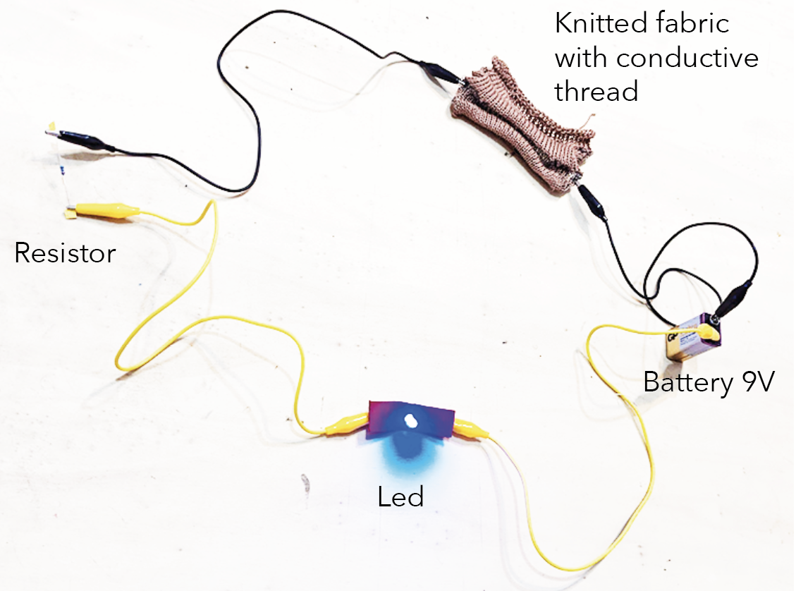
Wednesday, We had tutorial about how we made a first connection!
The longest leg of your led is the + After try to not break it - I broke it
We made embroidery with conductor thread. Big finger child trying to be focusing = bad embroidery but understanding.
Finally the led is brighting! I didn't feel ok with my sewing. And decided to start again with another pieces of fabric.
In parallel I start to understand how is important to document here, day after day and not doing all in the same time... After I'm being stress and in the rush. Maybe little by little will be better. I'm already late of yesterday.
Thursday,
We made a samples of Digital and Analog. In parallel we started Kombucha. And we did knitting in the lab.
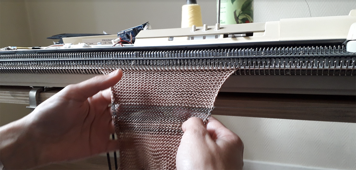
Friday, We went in the Textile lab for learning how to use the numeric embroidery and integrate electronic.
Some differents test of the week
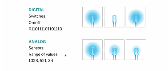
Digital sensor,
Digital = 1 or 0 / on off
Analog sensor,
Analog = multinumber / different values
For making analog sensor we use velostat.
Velostat also known as Linqstat, is a packaging material made of a polymeric foil (polyolefins) impregnated with carbon black to make it electrically conductive. It is used for the protection of items or devices that are susceptible to damage from electrostatic discharge. Source
Velostat is a piezoresistive material, meaning it’s electrical resistance decreases when pressured. When sandwiched between two conductive layers, it has a wonderful range for making pressure and bend sensors. It can also be used for resistive sensing over distance, position sensing. Source

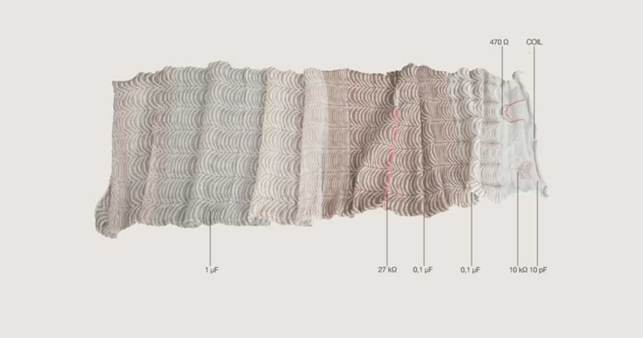
Conductive inks
We trying to make different inks with Laora Guillerm and Lauriane Beaumont:
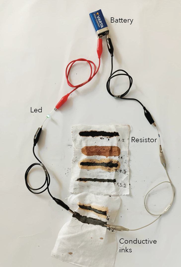
Some test with conductor ink dry :
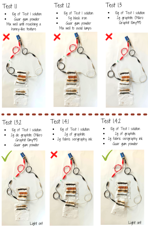
The others one was working before drying but after just this one. We discover when we make more contact it's working like a Analog sensor.
The lower the Ω, the more current flows
Arduino
It's : Hardware, Software, Community
- control a led
- read a sensor
- to control a led based on the interaction with the sensor
We do we need :
- make a circuit ( with Arduino)
- write the code for the circuit
1- Blink a led
/*Emma Pareschi - Fabricademy 2022/2023
 * I turn on a led and I turn it off
 * The Led is connected to pin 3
 */

int led_pin = 3; //defin the pin where the Led is connected in the digital part.

void setup() {

  pinMode(led_pin, OUTPUT); //define pin of the Led as an output

}

void loop() {

  digitalWrite(led_pin, HIGH); //turn the Led on
  delay(10);                 //wait 1000millisecond
  digitalWrite(led_pin, LOW);  //turn the Led off
  delay(900);                 //wait 1000millisecond

}
Int = where we define the led in the arduino.
Void loop = loop of the action we want.
The line delay is for changing the vitesse of animation of the led.
2- Digital Sensor
/*Emma Pareschi - Fabricademy 2022/2023
 * we read the value of a digital sensor connected to pin digital_sensor_pin and
 * we print it on the Serial Monitor
 */

int digital_sensor_pin = 8;     //change the pin, where the sensor is connected
int digital_sensor_value = 0;   //variable in which we save the sensor voltage

void setup() {
  // put your setup code here, to run once:

  //pinMode(digital_sensor_pin, INPUT);
  pinMode(digital_sensor_pin, INPUT); //define the pin as INPUT PULLUP
  Serial.begin(9600); //open communication

}

void loop() {
  // put your main code here, to run repeatedly:
  // digitalRead(pin);
  digital_sensor_value = digitalRead(digital_sensor_pin); // read the sensor

  Serial.print("the status of the sensor is: ");
  Serial.println(digital_sensor_value); //print the value
  delay(100);

}
💡 **For opening the windows with : The status of the sensor.
Go in Arduino > Tool > Monitor series**
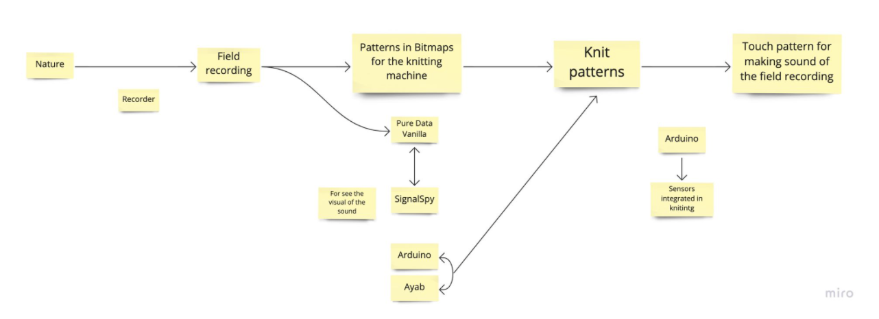
SOUNDKNIT Project
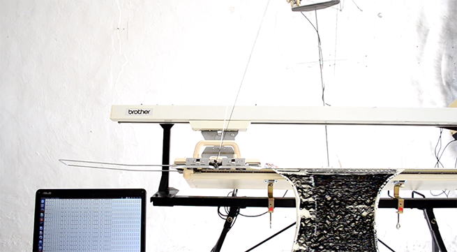
At the same time I'm still stuck on my idea to make a visual sound representation on knitting and then to be able to listen to it again. It's such a long time now I have this idea in my brain. I start knitting machine two years ago during my master degree in textile industry. I feel completely passionate about it and obsess about it. I was looking of projects and discover the projects of Claire Williams, which are exposed above. My choice was directly going for a Brother KH910 with 2 beds.
I didn't really have time before to continue exploring my idea of mixing knitting patterns and music. This week of E-textile gave me the motivation to get back into it and move forward in my research and understand how this was possible.
The SOUNDKNIT project is a great help to get started.
I started with a small diagram that is not finished I am bloqued on the continuation and to see the elements which they miss for that it functions.
References
Miller Smith Puckette (born 1959)
is the associate director of the Center for Research in Computing and the Arts as well as a professor of music at the University of California, San Diego, where he has been since 1994. Puckette is known for authoring Max, a graphical development environment for music and multimedia synthesis, which he developed while working at IRCAM in the late 1980s. He is also the author of Pure Data (Pd), a real-time performing platform for audio, video and graphical programming language for the creation of interactive computer music and multimedia works, written in the 1990s with input from many others in the computer music and free software communities.

PDF : The Theory and Technique of Electronic Music
Process and workflow
I try to follow the instruction of this project SoundKnit project in Github But It's not easy when your are not programer or familiar of this. Aswell this it's create for the Brother KH940 and i have a KH910. But let'see...
Tools
- Pure Data Vanilla
- Github E textiles Soundknit
- Ayab, for the hacking of the knitting machine
- Some tutorial about Pure data Vanilla
1- Arduino
I follow the first instruction of the github.
- Branch the arduino to your laptop
- Open the software
- Add this code in the new sketch :
// Use this sketch to set up the THRESHOLD value in the main Arduino code
// #define THRESHOLD 400 // end lines sensors threshold

int endLineLeftAPin = 1;
int endLineRightAPin = 0;

void setup(){
  Serial.begin(115200);
}

void loop(){
  int valueEndLineLeft = analogRead(endLineLeftAPin);
  int valueEndLineRight = analogRead(endLineRightAPin);
  Serial.print(valueEndLineLeft);
  Serial.print("\t");
  Serial.println(valueEndLineRight);
}
- Validate and make transmission
- Open a new sketch and ad this one
/*
BROTHER KH-940
2022 (c) maurin.box@gmail.com
Used hardwear : AYAB shield V1.0 https://github.com/AllYarnsAreBeautiful/ayab-hardware
*/

#include <Wire.h>

// HARDWARE CONSTANTS
#define BAUDRATE              115200   //
#define STITCHES              200      // Number of stitches
#define PHASE_ENCODER_MIN     0        //
#define PHASE_ENCODER_MAX     24       //
#define STITCHES_BYTES        25       //

//#define STITCHES_PIN        A4       // I2C hardhare / Connected to the IO expander
//#define CLOCK_PIN           A5       // I2C hardhare / Connected to the IO expander

// HARDWARE INPUT SYSTEM
#define ENC_PIN_1             2        // Encoder 1 - stitches encoder (interrupt driven)
#define DIR_ENC_PIN           3        // Encoder 2 - cariageDir encoder
#define ENC_PIN_3             4        // Encoder 3 - phase encoder
#define END_PIN_R             A0       // End Of Line Right for analog in
#define END_PIN_L             A1       // end Of Line Left for analog in
#define PIEZO_PIN             9        // Not used
#define I2C_ADDR_SOL_1_8      0x20     // IO expander chip addres
#define I2C_ADDR_SOL_9_16     0x21     // IO expander chip addres

// SOFTWARE CONSTANTS
#define THRESHOLD             500      // End lines sensors threshold
#define STITCHE_START_L       1        // 1
#define STITCHE_START_R       201      // 199
#define HEADER                64       //
#define FOOTER                255      //

boolean phaseEncoderState = false;     // Phase encoder state
boolean lastPhaseEncoderState = false; // Phase encoder last state
boolean cariageDir = false;            // Carriage direction 0:unknown 1:right 2:left
boolean toggel_right = true;           // boolean to sens the RISING age of the phase encoder when the carriage going RIGHT
boolean toggel_left = true;            // boolean to sens the RISING age of the phase encoder when the carriage going LEFT
boolean startLeft = false;
boolean startRight = false;

uint8_t serialData[STITCHES] = {0};       // One byte per stitch

uint8_t stitchBin[STITCHES_BYTES] = {     // One bit per stitch
  0, 255, 0, 255, 0, 255, 0, 255, 0, 255,
  0, 255, 0, 255, 0, 255, 0, 255, 0, 255,
  0, 255, 0, 255, 0
};

int16_t stitchPos = 0;                  // Carriage stitch position
uint8_t phaseEncoderCount = 0;
uint8_t solenoidesPos = 0;
boolean updateSolenoides = false;

boolean DEBUG = true;                 // boolean for serial DEBUGING

////////////////////////////////////////////////////////////////////////////////
void setup() {
  Serial.begin(BAUDRATE);
  Wire.begin();
  pinMode(ENC_PIN_1, INPUT_PULLUP);
  pinMode(DIR_ENC_PIN, INPUT_PULLUP);
  pinMode(ENC_PIN_3, INPUT_PULLUP);
  attachInterrupt(0, stitches_ISR, RISING); // Interrupt 0 is associated to digital pin 2 (stitches encoder)
}

////////////////////////////////////////////////////////////////////////////////
void loop() {
  // Start from the LEFT and look if LEFT end lignes sensors is passed
  if (cariageDir && analogRead(END_PIN_L) > THRESHOLD && toggel_left == true) {
    toggel_left = false;
    startLeft = true;
    stitchPos = STITCHE_START_L; // Set the stitch count to absolut stitchPosition
    phaseEncoderCount = PHASE_ENCODER_MIN;
    if (DEBUG) Serial.println(), Serial.print(F("START_LEFT = ")), Serial.print(stitchPos);
  }
  // Start from the LEFT and hit the RIGHT end lignes sensors
  // if the sensor is hited then ask to the computer to send the next array of values
  if (cariageDir && analogRead(END_PIN_R) > THRESHOLD && toggel_right == true) {
    toggel_right = false;
    startLeft = false;
    if (DEBUG) Serial.println(), Serial.print(F("STOP_RIGHT = ")), Serial.print(stitchPos);
    if (!DEBUG) Serial.write(HEADER);
  }
  // Start from the RIGHT and look if the RIGHT end lignes sensors is passed
  if (!cariageDir && analogRead(END_PIN_R) > THRESHOLD && toggel_right == false) {
    toggel_right = true;
    startRight = true;
    stitchPos = STITCHE_START_R; // Set the stitch count to absolut stitchPosition
    phaseEncoderCount = PHASE_ENCODER_MAX;
    if (DEBUG) Serial.println(), Serial.print(F("START_RIGHT = ")), Serial.print(stitchPos);
  }
  // Start from the RIGHT and hit the LEFT end lignes sensors
  // if the sensor is hited then ask to the computer to send the next array of values
  if (!cariageDir && analogRead(END_PIN_L) > THRESHOLD && toggel_left == false) {
    toggel_left = true;
    startRight = false;
    if (DEBUG) Serial.println(), Serial.print(F("STOP_LEFT = ")), Serial.print(stitchPos);
    if (!DEBUG) Serial.write(HEADER);
  }
  if (updateSolenoides) {
    updateSolenoides = false;
    if (cariageDir && solenoidesPos == 0) {
      writeSolenoides();
    }
    if (!cariageDir && solenoidesPos == 6) {
      writeSolenoides();
    }
  }
}

//////////////////////////////////////////////////////
void serialEvent() {
  static uint8_t byte_index = 0;                // Index for incomming serial bytes

  uint8_t inputValue = 0;
  uint8_t stitchBin_bitIndex = 0;
  uint8_t stitchBin_byteIndex = 0;

  if (Serial.available() > 0) {
    inputValue = Serial.read();
    if (inputValue != FOOTER) {
      serialData[byte_index] = inputValue;
      byte_index++;
    } else {
      for (uint8_t byteIndex = 0; byteIndex < STITCHES_BYTES; byteIndex++) {
        stitchBin_bitIndex = byteIndex % 8;
        if (serialData[byteIndex] == 1) {
          bitSet(stitchBin[stitchBin_byteIndex], stitchBin_bitIndex);
        } else {
          bitClear(stitchBin[stitchBin_byteIndex], stitchBin_bitIndex);
        }
        if (stitchBin_bitIndex == 7) stitchBin_byteIndex++;
      }
      byte_index = 0;
    }
  }
}

void stitches_ISR() {
  cariageDir = digitalRead(DIR_ENC_PIN);
  lastPhaseEncoderState = phaseEncoderState;
  phaseEncoderState = digitalRead(ENC_PIN_3);
  if (startLeft || startRight) {
    updatephaseEncoderCount();
    updateStitchPos();
    updateSolenoides = true;
    if (DEBUG) printOut();
  }
}

inline void updatephaseEncoderCount () {
  if (phaseEncoderState != lastPhaseEncoderState) {
    // Carriage go LEFT to RIGHT
    if (cariageDir && phaseEncoderCount < PHASE_ENCODER_MAX) {
      phaseEncoderCount++;
    }
    // Carriage go RIHT to LEFT
    else if (!cariageDir && phaseEncoderCount > PHASE_ENCODER_MIN) {
      phaseEncoderCount--;
    }
  }
}

inline void updateStitchPos () {
  // Carriage go LEFT to RIGHT
  if (cariageDir && stitchPos < STITCHE_START_R) {
    stitchPos++; // increase stitch count
  }
  // Carriage go RIHT to LEFT
  else if (!cariageDir && stitchPos > STITCHE_START_L) {
    stitchPos--;
  }
  solenoidesPos = (stitchPos % 8);
}

inline void writeSolenoides() {
  if (cariageDir) {
    if (!phaseEncoderState) {
      Wire.beginTransmission(I2C_ADDR_SOL_1_8);
      Wire.write(stitchBin[phaseEncoderCount]);
      if (DEBUG) Serial.println(), Serial.print(F("WRITE_1_8"));
    } else {
      Wire.beginTransmission(I2C_ADDR_SOL_9_16);
      Wire.write(stitchBin[phaseEncoderCount]);
      if (DEBUG) Serial.println(), Serial.print(F("WRITE_9_16"));
    }
  } else {
    if (!phaseEncoderState) {
      Wire.beginTransmission(I2C_ADDR_SOL_9_16);
      Wire.write(stitchBin[phaseEncoderCount]);
      if (DEBUG) Serial.println(), Serial.print(F("WRITE_9_16"));
    } else {
      Wire.beginTransmission(I2C_ADDR_SOL_1_8);
      Wire.write(stitchBin[phaseEncoderCount]);
      if (DEBUG) Serial.println(), Serial.print(F("WRITE_1_8"));
    }
  }
  Wire.endTransmission();
}

// Print out DEBUGING values
inline void printOut() {
  Serial.println();
  Serial.print(F(" CariageDir: ")), Serial.print(cariageDir);
  Serial.print(F(" PhaseEncoderState: ")), Serial.print(phaseEncoderState);
  Serial.print(F(" phaseEncoderCount: ")), Serial.print(phaseEncoderCount);
  Serial.print(F(" StitchPos: ")), Serial.print(stitchPos);
  Serial.print(F(" SolenoidesPos: ")), Serial.print(solenoidesPos);
}
-
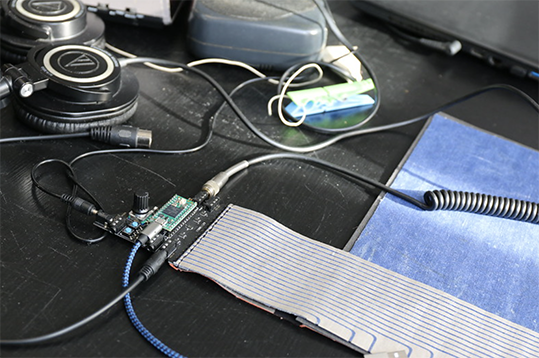
After I went in my knitting machine and Add the Arduino to my Ayab card for see if it's working differently. I didn't really understand this action of Arduino will be changing for after.
-
Try to play with Ayab, but I still have my bug with my machine. She made a stranger lines. Some forum said it's the welds are not correctly fixed it. But anyway this is for another time to correctly fix it.
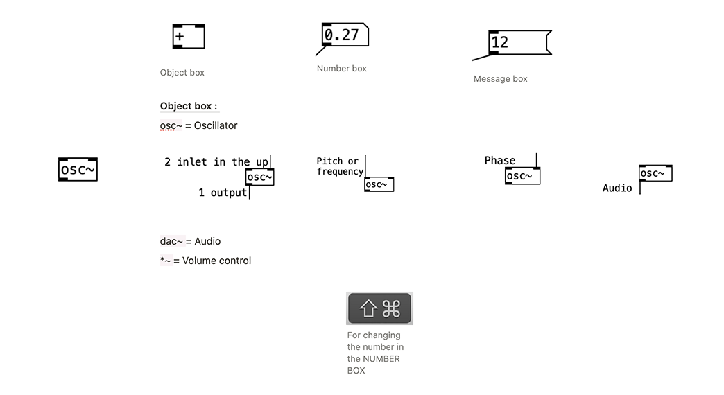
2- Pure Data Vanilla
1- Download it Pure Data Vanilla V0.5.x
http://msp.ucsd.edu/software.html
http://puredata.info/docs/StartHere/
I actually use MAC version.
I watched some tutorials for understanding the interface. And download in the sae time others software for having an oscilloscope.
Some differents one I found on the web. For windows the Multi Channel oscilloscope software: https://www.tiepie.com/en/download
For Mac : Ispectrum free https://macdownload.informer.com/ispectrum-analyzer/download/
or Signal Spy 5€ https://apps.apple.com/us/app/signalspy-audio-oscilloscope-frequency-spectrum-analyzer/id912509512
The basics fonction on Pure Data Vanilla
I'm going back for follow the instruction of the Github SoundKnit
- I Add the plugins
I'm not really sure of myself because one of them talk about windows but the softaware said is Add. Let's see in the future.
- I was lost in this part for arriving to transform the code in Github in the file for Pure Data Vanilla. But finding a solution...
I downloaded an another patch in the website PD.
And open it with text Edit for see the code inside.
I copy in the page page and add it, renomed the file.
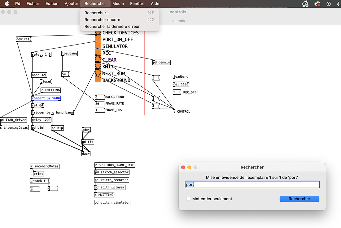
The code for the patch SoundKnit

The file here
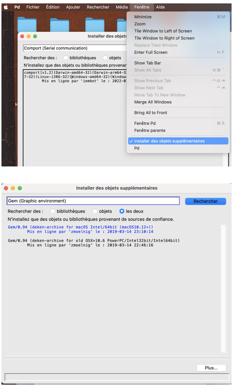
- Branch the Arduino on the laptop
- Go in PD open the file. Normally when we click in CHECK DEVICES something changing but for me nothing. Only in my Arduino card the orange light is flashing.
I try to watch on it for see if I looking on the "port" I will find something.