WEEK 05 : E-textiles
What are E-textiles?
As described in the website of Fibre2Fashion :
"E-textiles have made a computer wearable. These intelligent fabrics have electronics embedded in them and facilitate digital components. Electronic textiles make use of conductive fibres and the electronic parts are innate to the fabric. Hence e-textiles are made up of minuscule conductive fibres, which exist naturally or are specially treated to be conductive. They are used to make clothes, in interior designing, medical care, and safety purposes. E-textiles can function as sensors, data transfer systems, antenna, thermo chromic displays, and heating elements."
E-textiles are very useful in the medical field, since they can give information about one patient's temperature,
Inspirations
Doing researches about E-textiles, I discovered something very interesting:
Tattooed electrical circuits
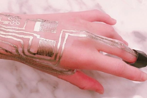
From the website above, I found that:
"Researchers made their new aid layer out of polyvinyl alcohol paste and calcium carbonate. The layer allowed scientists to fuse the ultra-thin layer of metal patterns to the sensor using a hair dyer set on cool. The resulting device is flexible and boasts all the necessary electromechanical characteristics." I will address this during the Week 13 I guess.
Lauren Bowker, The Unseen :

Ted Talks, Lauren Bowker
The Unseen
Beyond sensor experience
"The world is full of unseen magic, we invite you to see the unseen."
She believes in magick and got pagan inspiration.
The pollution absorbent jacket : color changes when the air is polluted, it goes from yellow to black.
Next project
Combines science and aesthetic. feathers are also changing color according to the air.
Audrey Briot
And, of course, the work of Audrey Briot
I was curious to know if printing could be a way to produce conductive paths. It appears that etching work well on conductive fabrics. Have to try this!
- Rice paste resist etching conductive fabrics
Afroditi Psarra
Afroditi Sparra, Fractal Antennae
Conductive plants 
Can plants be conductive?
Actually, mosses, when doing the process of photosynthetis, produce energy that can be converted into electricity. The "Moss Table" was created in this way. Nonetheless, according to the website below, the amount of energy created here is very low (1000joules/day, so O.27Watts approximatly)
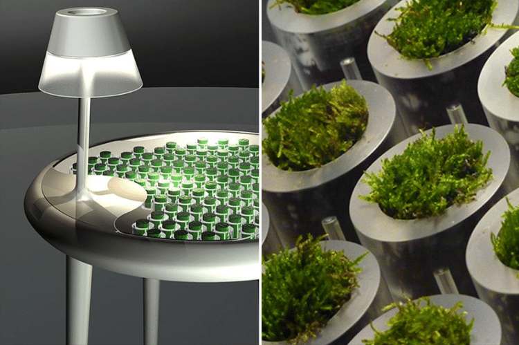
No matter what, this is highly interesting.
The sound of nature, Kobakant
Alright! If plants cannot conduct electricity (except with a conductive gel injected into the stem), we nonetheless can work with plants to create some content in term of data!! The project "The sound of nature" headed in Antananarivo is displaying the possibility to hear from plants!
Annex researches
Bioluminescence

My goal, this week, is to try as many techniques as I can, because these techniques could be part of my final projects. I would like to explore the possibilities in term of programming with Arduino for instance.
Vocabulary and translation if needed
Flexible PCB: Circuit imprimé flexible
---
Electricity basis

The multimeter
When it comes to electricity, one of the most useful device you will need is the multimeter.
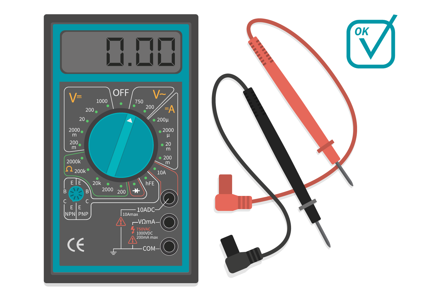
Testing the multimeter
Turn the button on the "Continuity" function, and put it on "Ohms" position (Ω).
You have two threads : one black and one red. Put the red one in the Ohms hole of the multimeter, and the black one in the COM hole of the multimeter.
To test if the multimeter works well, press the endpoints of the black and red threads together. Depending on the type of multimeter, it will make a sound, it will turn on or indicate 0 on the screen. If it does so, your multimeter is working.
Then, put the endpoint of the black thread and the red thread at two extremities of the thread or circuit you are testing the conductivity of.
If the value written on the screen is less than 100 Ohms, the thread/part of the circuit is working.
If it is written "OL", then the electricity is now running through the thread/circuit : maybe the circuit is opened, a conductive thread is cut, etc...
Warning : if the two extremities you want to tests are too far from each other, then the multimeter may not be working well, there are some limits to it.
About resistors
Calculation of your resistors' power (in Ohms)
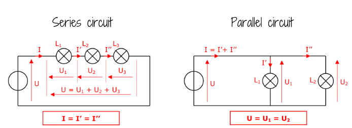
First approach on sensors :
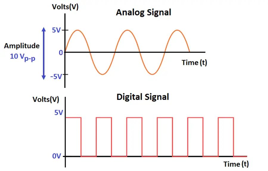
To understand the difference between digital and analog sensors, here is a little schema that helps:
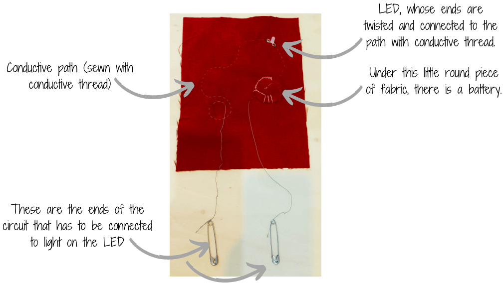
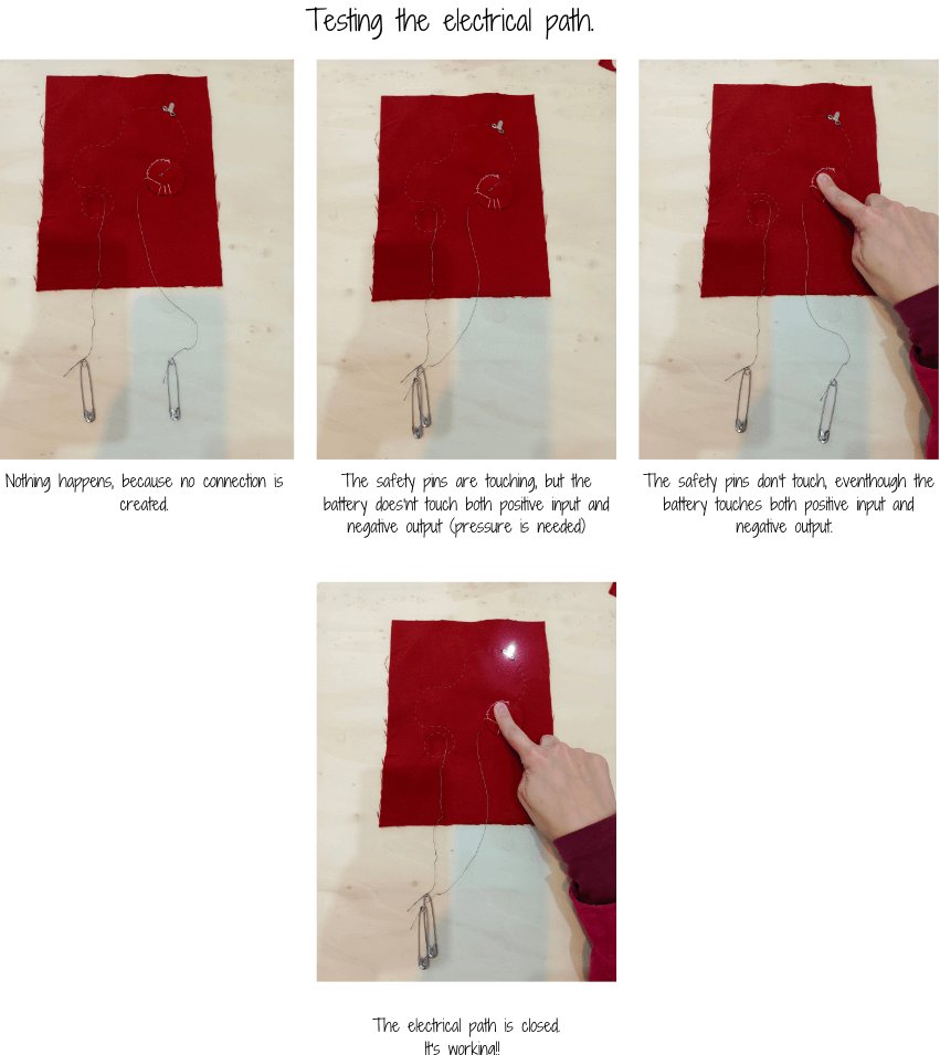
Then we started by doing a sensor (a conductive path) embedded into fabric (here, some wool felt).
Digital sensor
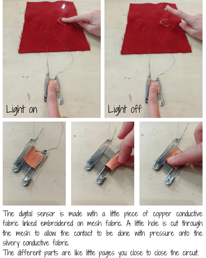
Digital sensor work with 0 and 1. The switch is either ON, either OFF, there is nothing in between.
Analog sensor
On the contrary, the analog sensor works with a range of numbers, depending on the level of pression you apply onto the sensor, that is to say that it produces analog output in correspondence to the quantity being calculated.
What you can see here is the subtle changes in term of intensity in the lightening of the LED. This is due to the Velostat I used as an analog sensor, and that I connected into my electrical circuit you saw above.
---
Arduino
Taking notes on the main concept of Arduino:
Ted Talks, Massimo Banzi, one of the creator of Arduino
Interaction between object and people.
Even kids can use it.
Sketching with electronics.
Mashup of open source technologies that would be hard to individually take in charge.Exemples of projects:
-The Enough Already
-Sign Language Glove, Kendall Lowrey
-Botanicals: well being of plants.
Use of Arduino
With Arduino, we can transfer a range of information in term of pressure for instance (On Velostat) in a range of information concerning the brightness of a light. It helps controlling better the variations of the light depending on the light.
With Velostat, the size of the surface is important. The more surface you press, the brighter the light will be.
Polyethylene-Carbon Composite (Velostat®) Based Tactile Sensor isn't too expensive, and isn't too difficult to find.
About programming in Arduino
The following information were found on the french website of Developpez.com and on the following website.
These sites are french ones, for it helped get some subtle information I couldn't understand easily in English.
Syntaxic colors
Orange: keys words that Arduino recognizes to be existing functions.
When selecting an orange word: right click > "Find in reference" > opens, the documentation of the selected function.
Blue: key words that Arduino recognizes to be a constant.
Grey: comments that won't be executed by the program. It's useful to comment the code to avoid getting lost into it, or to make it understandable for someone else.
2 different ways to make a comment:
-in a line of code, everything after "//" is a comment
-several lines of code that we want to be comments can be circumscribed by "/" and "/"
Ponctuation
Every line of code ends will a semicolon ";"
A function content is delimited by braces "{" and "}"
Parameters of a function are held into brackets "(" and ")"
Function
What is a function?
A function is an instructions sequence that achieves a calculation or a task. It can contain input settings and can also return some output values.
A function must be stated one, and it can be called up at several occurences.
PinMode
pinMode(pin, mode)
-"Pin" being an allusion to the number of the pin on the Arduino board.
-"Mode": either input, output or input-pullup (this last one being an input when an internal resistance added to it)
Arduino Uno board
This board is a programming interface.

Understanding Arduino's language
Right below is a piece of Arduino code to make a LED blink every 500ms.
> const int LED=2;

 void setup()   {
    pinMode(LED, OUTPUT);
 }
 void loop(){
    digitalWrite(LED,HIGH);
    delay(500);
    digitalWrite(LED,LOW);
    delay(500);
 }
The LED is connected to the pin 2.
setup of the program (only occurs once)
The LED will be the output
Loop of the program (that will happen over and over)
The LED goes to its higher power
During 500 ms
The LED goes to its lower power
During 500 ms
Arduino course:
Code example 1 :
I melted 2 exercices by mistake: the Digital sensor one and the blink one. Here is the result in code, and then in video:
int led_pin = 8; //defin the pin where the Led is connected

void setup() {

  pinMode(led_pin, OUTPUT); //define pin of the Led as an output

}

void loop() {

  digitalWrite(led_pin, HIGH); //turn the Led on
  delay(200);                 //wait 1000millisecond
  digitalWrite(led_pin, LOW);  //turn the Led off
  delay(50);                 //wait 1000millisecond

}
Digital switch and Arduino - Serial Monitor
Analog sensor and Arduino - Plotter Monitor
Calculation of the needed resistor:
Resistance measure:
- 31 KOhms when huge pressure (when the current flow is the highest)
- 45 KOhms max (when the current flow is the lowest)
In average: 60.5 KOhms
Here is what you can see when working with an analog sensor in Arduino with the following code:
// Define the number of samples to keep track of. The higher the number, the
// more the readings will be smoothed, but the slower the output will respond to
// the input. Using a constant rather than a normal variable lets us use this
// value to determine the size of the readings array.
const int numReadings = 10;

int readings[numReadings];      // the readings from the analog input
int readIndex = 0;              // the index of the current reading
int total = 0;                  // the running total
int average = 0;                // the average

int inputPin = A0;
int led_pin = 3; //change the pin of the Led

void setup() {
  // initialize serial communication with computer:
  Serial.begin(9600);
  // initialize all the readings to 0:
  for (int thisReading = 0; thisReading < numReadings; thisReading++) {
    readings[thisReading] = 0;
  }

    pinMode(led_pin, OUTPUT);   //initialize led pin
}

void loop() {
  // subtract the last reading:
  total = total - readings[readIndex];
  // read from the sensor:
  readings[readIndex] = analogRead(inputPin);
  // add the reading to the total:
  total = total + readings[readIndex];
  // advance to the next position in the array:
  readIndex = readIndex + 1;

  // if we're at the end of the array...
  if (readIndex >= numReadings) {
    // ...wrap around to the beginning:
    readIndex = 0;
  }

  // calculate the average:
  average = total / numReadings;


  // send it to the computer as ASCII digits
  Serial.println(average);
  average = map(average, 1023, 430, 0, 255); //we change the range
  average = constrain(average, 0, 255); //we apply the limits

  delay(50);        // delay in between reads for stability
  analogWrite(led_pin, average);
}
To get this graph:
Go in Tool
Serial Plotter
Explaining this line : average = map(average, 430, 1023, 0, 255)
0,255 > corresponds to the LED states of lightness
1023, 430 > corresponds to the pressure level of your analog sensor, here a piece of Velostat. The hard you press it, the lower will be the numbers. 1023 is a general number you cannot choose. To find the 430, we had to test our material before.
So: When you don't press the analog sensor, you get 1023 in your plotter monitor, and the light is on 0 (OFF). If you press half the maximum pressure possible, you will get 296 and the light will be half its maximum strengh. If you press it to the maximum, you will get 430 in your plotter monitor and the light will be at its maximum brightness.
---
Conductive inks
About conductive ink
Again conductive ink
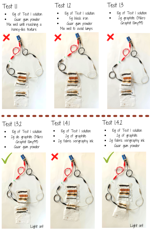
We had the will to test several recipes of inks, in order to see if they are conductive. We know it exists in shops, but we wanted to know if it was possible to produce our own conductive ink.
Test 1 solution: Iron acetate
100ml Vinegar 8%
6g Iron sulfate
5g soda ashes powder
Guar gum powder
Add the vinegar, the iron sulface, mix well until it dissolved, then add the soda ashes powder.
When we tested it the first place, we were so pleased to realize that every inks were working!!
But... actually it appeared that water from the ink hadn't dried enough, and that was the part that was conductive, because we re-tested it in order to take great pictures and it appeared that some of our previous results were fake results.
These are the real ones we obtained:
And... we discovered something quite interesting:
)
---
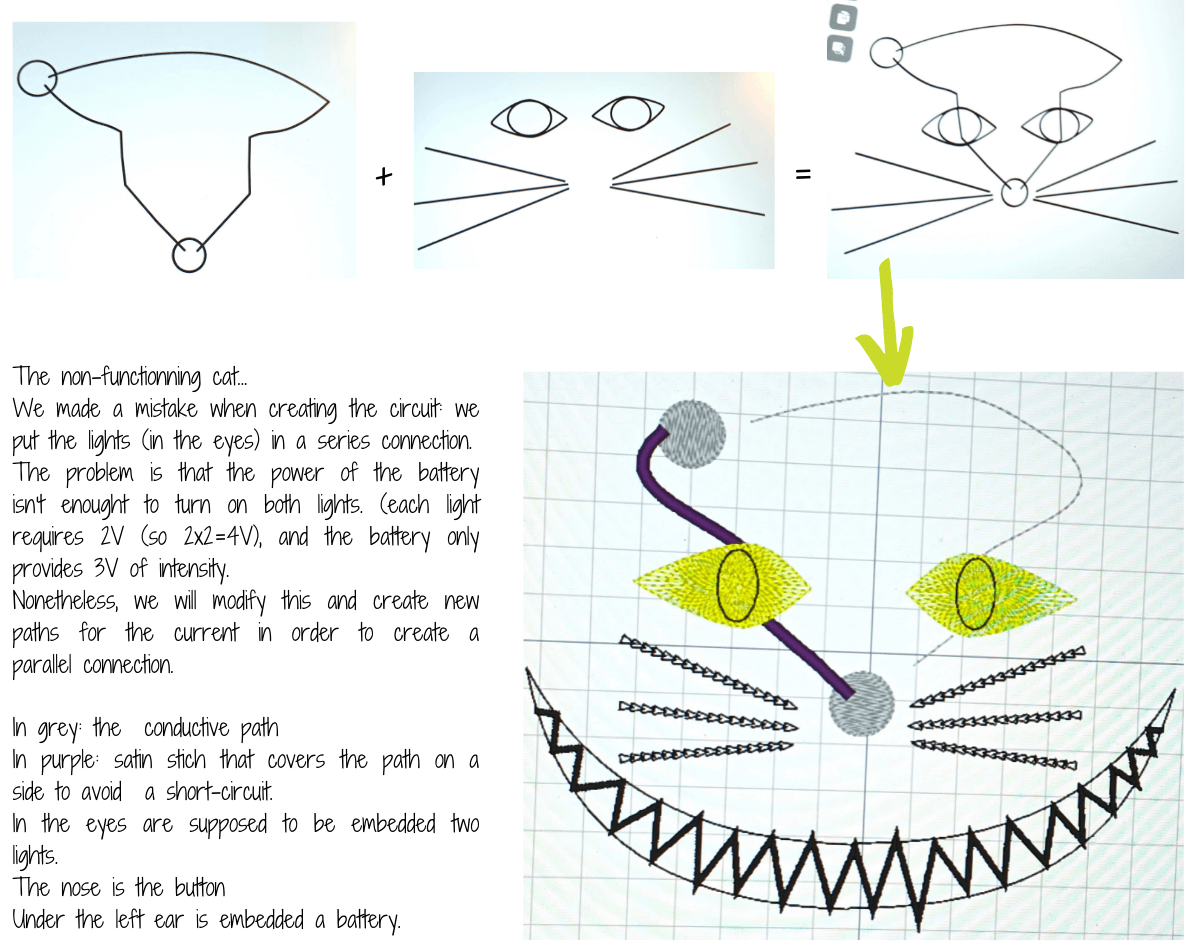
The embroiderer machine
In group, we designed a cat to be embroidered with the embroiderer machine. It is a cat, and when you press its nose, its eyes are lighting up.
Bill Of Material
To make such a Alice in Wonderland's cat, you will need :
1 piece of dark blue felt
2 Felx Maker V1 Wearables LEDs
1 coil of thin conductive thread (it has to be thin enough to be embroidered with the embroiderer machine) : H12 or H40
1 battery of 3V
Here is the testing part of it with the multimeter ! (filmed by Audrey Kalic)
---
The knitting machine
Amandine, one of our colleagues, knows how to use the knitting machine, and she taught some of us the basis of using it.
What we wanted to try was integrating conductive thread into regular knitting. The used wool is the orange-like, and the conductive thread is grey. This was an attempt that allowed us to experiment with the knitting machine : learning how to thread the machine, to start and finish the work.
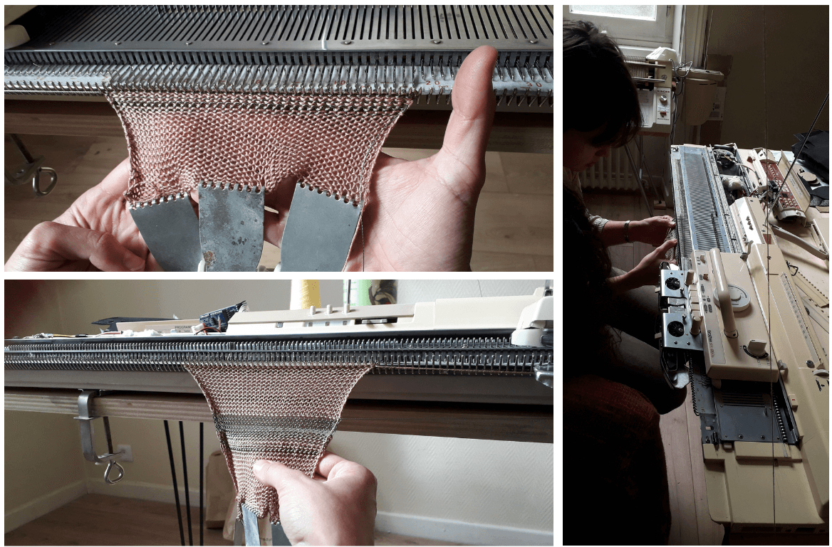
The final experiment was 20 cm x 15 cm test.
---
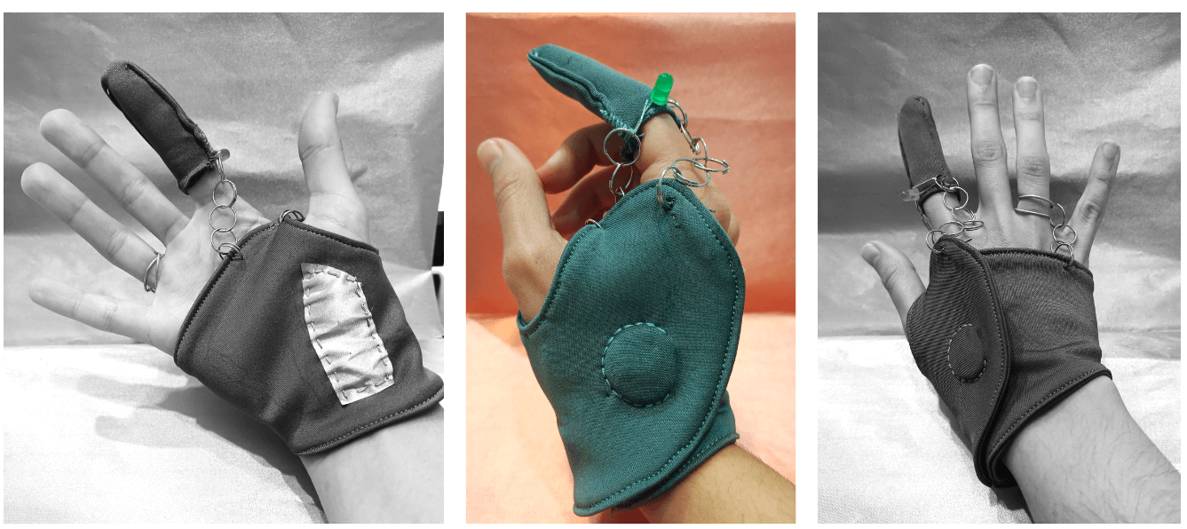
Creating a conductive mitten^1
I wanted to use the topics we had studied during the whole week to create something.
During the week, I had the thought that what we were doing was king of magical: there was some magic in the air.
So, what could be better that creating a glove (or a mitten) that could give some magic powers to anyone?
Inspirations in term of form


1/ Creating a pattern fitting the hand.
2/ Imagining the conductive path (electrical circuit) in it. I wanted to use some metallic circles that are normally meant to be part of jewellery, for I wanted this mitten to be something aesthetical and jewellery-like. These metallic circles are conducting electricity, so they became part of my electrical circuit.
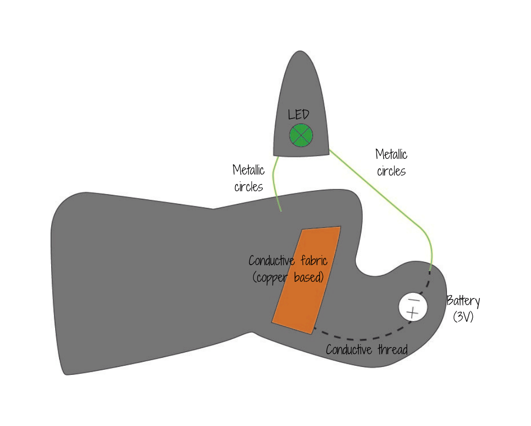
3/ Testing it with conductive fabric
4/ It works, and here it is!
Conclusion of this week
Following the lesson wasn't easy, for new terms and pratices were going too fast for me (and for more of the people who were following the online course with me).
No connection with this week, but I just wanted to add this site