09 Textile Scaffold
The project this week is textiles as scaffold. Theres alot to that can be done within this field so I decided to focus on one material and try to do something with that.
Fish Leather
I actually collected all the offcuts of the fish leather from the projects around the Fabricademy Iceland Bootcamp in 2019 and they have mostly be sitting in my house since then. I have used some to make some earrings but I hate waste so this week I decided to try and find ways of reusing these offcuts. I was actually surprised how little has been done with this material before, its all just tourist purses and earrings. Here are some of the projects that were interesting in a similar way to what I wanted to achieve. At the bootcamp, Ingi Freyr did a workshop on CNC milling and leather moulding. I made a piece moulded around stones at the time, so I plan to use some of this knowledge now I have the time to develop the project.
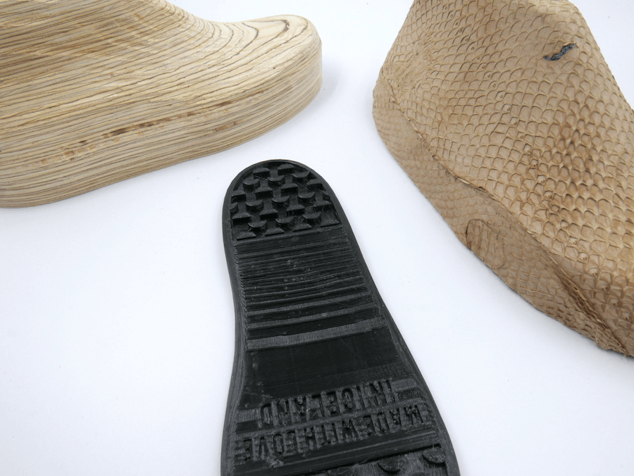 Fish Leather Shoe by Ingi Freyr at the Icelandic Fabricademy Bootcamp via Flickr
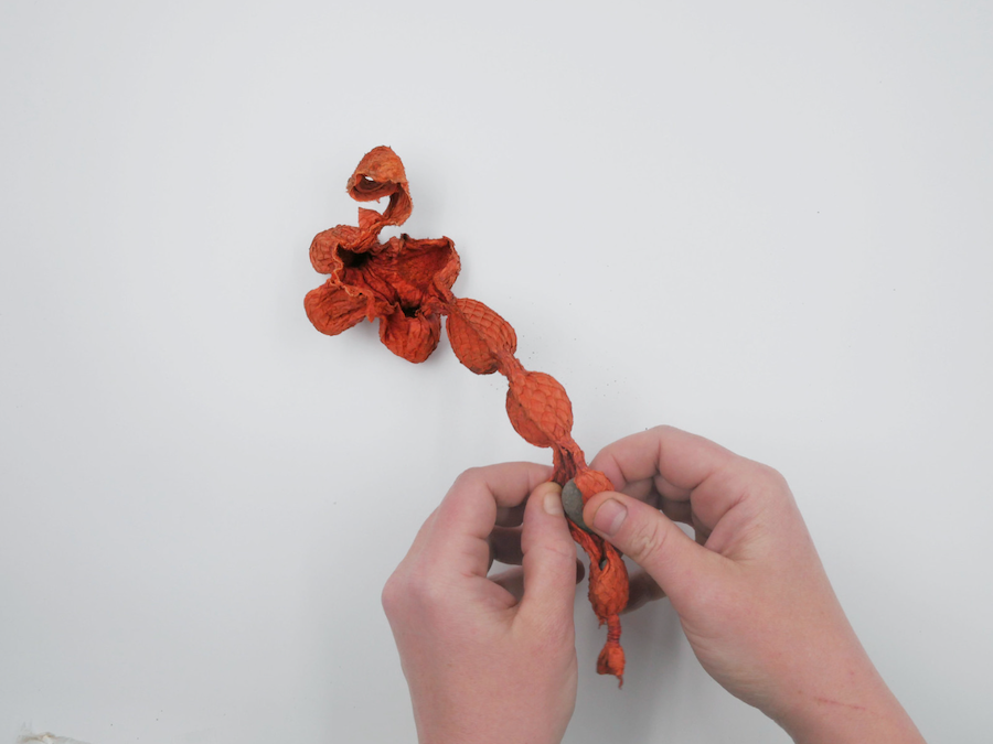 Unwrapping my fish leather moulded by stones via Flickr
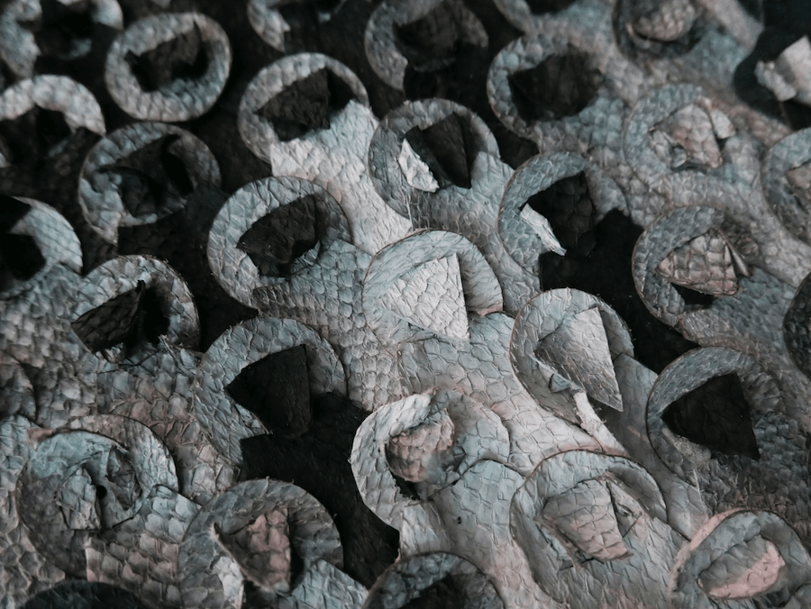 One of The Projects I collected the Fish Leather Waste from via Flickr
Jorge Penadés
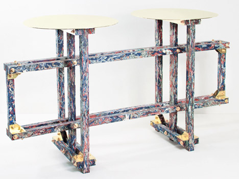
Spanish designer Jorge Penadés has created furniture made from shredded leather moulded together with natural bone glue. I love how you can see the layers of the textiles trapped in the glue. I like the way its been sanded to look almost like a marble.
Formafantasma
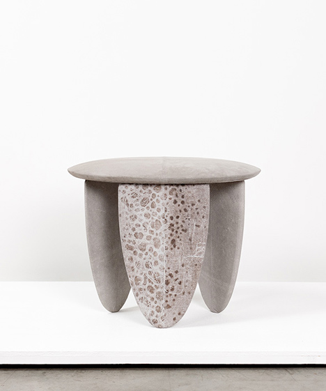
Formafantasma is a research-based design studio investigating the ecological, historical, political and social forces shaping the discipline of design today. In this project Craftica, a collaboration with Fendi they are returning design into a pre industrial era using modern design estectics with old world materials including fish leather. I love the moulding of the perch skin on this stool. It looks like concrete.
Fabien Barrero and Carsenat
[Fabien Barrero and Carsenat] created Pinus Pinaster, a set of cheese cover sets made from moulded pine resin. These are made in a variety of ways from moulds to glass blowing. After seeing Margréts coffee and pine resin project I decided to research pine resign and seeing these gave me the idea that it is strong enough to use pine resin to trap my fish leather in.
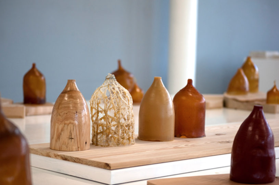 Pine Resin Cheese Covers by Fabien Barrero and Carsenat
Pine Resin
My first adventures started with some tree tears harvested from trees that produce this substance when it they are injured as a protective seal. There really wasn´t alot of info out there for using it as I wanted to, to trap textiles in but I decided to use a recipe that Margret had used in Bioplastics week that had worked quite well with sand and coffee as fillers.
Materials

    * [Pine Resin](https://en.wikipedia.org/wiki/Resin#Rosin) - 45gr
    * [Isopropyl Alcohol](https://en.wikipedia.org/wiki/Isopropyl_alcohol) - 20ml
    * [Carnauba wax](https://en.wikipedia.org/wiki/Carnauba_waxgr) - 5gr
    * [Fish Leather](https://nordicfishleather.com/)  - various amounts
    * [Glycerol](https://en.wikipedia.org/wiki/Glycerol) (one recipe) - 15ml

Tools

    * Pot, Not reusable.
    * Spoon.
    * Scale.
    * Baking Paper.
    * Silcon and Glass Moulds.
    * Cling Film.
    * Scissors.

Process

    * Measure out the ingredients.
    * Combine the resin and the alcohol in a pan, stir til the resin has melted.
    * Add in the Carnauba Wax and stir well until it has disolved.
    * This is the basic recipe with one pour I also added the Glycerol here.
    * Either stir in the chopped up fish leather or pour onto it
    * Mould into poured or manipulated shape.
    * Leave to cool down.
    * Un peel from Mould trim off edges.
Results
Bowls
The first thing I tried to do was to make a small pour test. After making the basic resin mixture I attempted to paint a little on a baking sheet for me to place some fish leather bits on before poring over another layer etc. as it turned out the resin died way to fast to really use this plan so I ended you just sprinking some leather over the area and then pouring the resin over the top of that. My intial thinking was to heat the substance to make it mouldable so I used the heat press to warm the substance. I had the temperature at 110°C for 1.30mins and that was enougth to shape the material over the glass I had prepared by covering it with cling film.
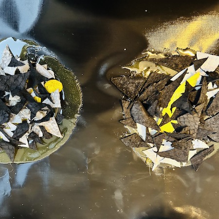
These tests were somewhat suscessful I was able to mould the substance onto the glass but it was difficult to see the pattern of the fish leather I had laid out. It was also very brittle so it just snapped anywhere there was no textile in it. It was than I decided to mix a bunch of grey natural salmon leather into the mix to see how that worked. The structure was much better and less brittle but you still couldn´t really see the fish leather as much as I would of liked.
Spikes
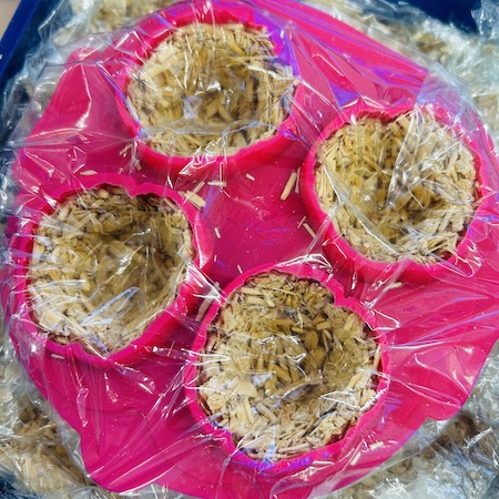
Here I decided that rather than having a free form moulding, I would use a silicon mould I had found in the local store that is actually used to drip fat from fried food (good for the heart). I liked the spikes so I make a small sample where I got some colours of leather and chopped up the triangles very small and placed then in a design in the mould.
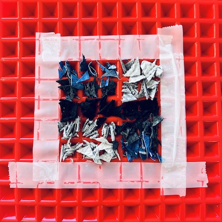
I was very happy with the initial result but after drying it actually broke but here you can see some of the bits.
I tried the same experiment but with a slighly bigger square of material. I also poured the mixture a little deeper. At the time of writing this piece is still flexible for some reason so Im still hoping that it will dry and stiffen at some point.
For my final experiment I decided to play with a couple of the variables. Firstly I tried to blend the fish leather to get smaller pieces. I was quite shocked at how much it didn´t like this at all. I managed to get a little bit of fluff out of it but now I know you would need an actual shreader to blend this further. I glued some larger pieces to the outside of the silicon vase mould I had got in the charity shop hoping to trap these shapes on the inside for a nicer finish but it didn´t really work out.
I also decided to add some glycerol just to see the effect on the material. It turned the resin more cloudy but also suprisingly more rigid when dried but I got a solid form that isnt too brittle. I am fairly happy with the final result.
Subtractive Manufacturing
Design
Substarctive manufacturing processes are based on the controlled removal of materials through cutting, drilling or milling to achieve the form. Here we are going to use the CNC Milling Machine in the FAB LAB Sauðárkrókur. I was quite excited about using the machine and luckiliy I felt I had created some really interesting forms in Grasshopper using the image sampler during week 07. I used one of these shapes for a 3d print so I would also like to use this for a fish leather mould.
So i went back into grasshopper to resize the shape. Due to the constraints of time and drill bits etc it was decided that our work could be roughly A4 size. It was also decided that we could only use 19mm MDF too so that I found to but a bit sad as I had envisioned making a larger differential in shape. I thought this would only give me the very top of the shape but after resizing with some help from Louise I ended up very happy with the resolution on the shape. We also made it a pair so we had a positive and negative side for mouulding. Again thanks to Louise for helping with this definition before going to the Fab Lab.
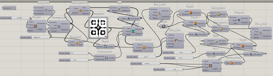 The Grasshopper Definition used to Create the CNC Mould Design.
Now I had the file correct in Grasshopper I baked this into Rhino. The CNC machine works on software called Vetric We Carve Pro and because of the license we had to use the computers at the fab lab to finalise the design that would run on the machine.
Learning By Failing
so of course this wasn´t going to go smoothly. My first problem was in the software. I had stupidly exported my file as export all not export selected so I had all my hidden layers popped up too so don´t do this.
I do not have the file as its not available but I wrote down the steps I took in it.
Vectric VCarve

    * New File for Single Bed.
    * Material (wood) Dimensions (x=90 x y=31 z=19mm) Surface = 0,0
    * Upload Design Checking Position of Model on Grey Surface Line (see below).
    * First Step - 3d Roughing to get most bulk out of it.
    * In Tool Database Select 1/4 Inch Straight Bit.
    * Second Step - Finishing to add Finer Detail.
    * In Tool Database Select 1/4 Inch Ball Nose Bit.
    * Check the Preview.
    * Mould Boundary (see below)
I had to back into grasshopper to make a split in the design to allow for a cutting line though the outside this didn´t work, I had hoped that the program would recognise the vector I drew around the form but I think it didnt work as it was a 3D model and the program didnt see the 2D form in there. Oh well I thought, I´ll just cut it.
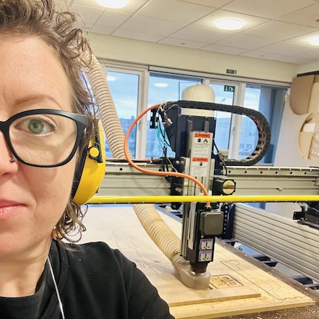
Calibrating
So far so good. I uploaded the file to a USB and then tranfereded that to the CNC comtrolling computer. I moved the drill bit away and figured out that my board should be attached to the spoil board (the board that protected the base of the actual cutting area from being damaged) I drilled 6 holes into the board and then screwed this down.
To set up the machine you just follow the instructions.
- Change the drill bit to the 1/4 Straight bit. Be careful in case it is hot. Make sure maching is off etc.
- Once it is securely attached find a good place to tell the machine what is the 0,0 point of the material so in this case it was the bottom right corner of the wood.
- Using the Alumninium piece attached to the drill bit hold this on the top of the wood and allow the drill bit to callibrate itself to zero on the z plane.
- The computer will prompt all of this instructions. It will ask if everything is calibrated. Once you are sure this is ok you turn on the green button to start the rotation of the drill checking it sounds "OK"
- Only then should you press OK and let the drilling begin.
Attempt 1
The first pass of the machine in 3D roughing seemed totally fine. Everything looked as it should. On the second pass however I was concerned with how much material was being taken. The first mould is actually quite tall compared to the second part and as it was finishing it seemed loose. Also I couldnt really see what was going on with the second mould as it had so much sawdust in it that it was difficult to see. The noise started to sound different in the second mould so I pressed THE SPACE BAR which is to pause the machine rather than THE BIG RED BUTTON which is the EMERGENCY STOP button. This is when we took a look and realised that the drill was cutting all the way into the spoil board. This was clearly not OK so I pressed the red button to reset the machine.
After a good think, I realised that I had been told to center the design under the grey line in the software so that the base board was underneath. It turns out this was completely wrong and the grey surface line needed to be below the base of the mould itself so I went back to the software, uploaded the design again, reset the depth and reuploaded the file again. Lucky the board I had selected had a extra space the was gonna be Birdies (Sorry Birdie.)
Even though one side of the design had been drilled away completely I did manage to save a piece of the other side that was fairly rough round the edges due to it only going through the 3D Roughing process but importantly it was still usuable.
Attempt 2
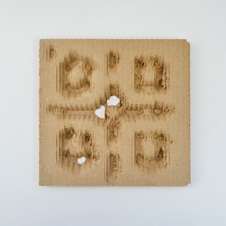
So we go back the the beginning again. Exactly the same as before but now the machine is cutting way less. It actually weant 3 passes over the 2 forms in 3D roughing but so far so good.
So far so good. It completed the 3D roughing and stopped and asked to change bit. We had selected a 1/4 ball nose bit which gives you a more rounded and smoother finish in the finishing process than the straight bit we used for roughing. We changed the bit as directed making sure calibrated again and it was in properly, or so I thought.
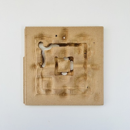
Initally the sound was ok on the first few passes as it went in the round rather than up and down as before but then the sound got really loud and really sharp so I preesed the pause button to check it. It seemed it had cut a very deep trench in the mould. It was suggested that the machine had maybe not calibrated the z axis properly and so if it was started again from the 0,0 point after being recalibrated then it should be fine. This particular mould at this point had some damage but I was quite fond of it so yes off we went again. The drill bit was overing over the parts it was supposed to cut away before so you can actually see how far away it was from the proper depth.
So far so good then as it started to cut again the noise was actually even worse so I paused it again. This time the drill bit was totally loose and really dangerous. I´d had enough at this point. I had one mould that was pretty functional for my needs and the rescue one from before plus this weird damaged one so I called it a day.
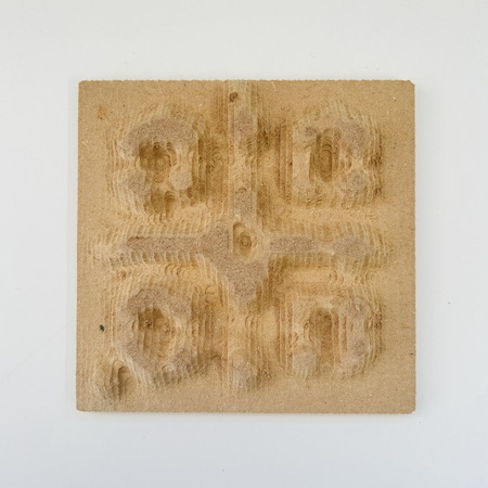
Finishing
At the end once they had been removed from the base wood, I sanded down the pieces a little to remove and lumpy parts.
Fish Leather Moulding
After working with the resin I decided just to go back to basics and test the fish leather with some simple flour glue. I cooked a pot with 1 part flour to 2 parts water and got to work.
Test
In this example i started by laying a layer of "lumpy" glue on some cling film and laying pieces of fish leather on it. As I was working, I noticed that the lumps of the flour glue I made looked pretty gross so I started rubbing the flour glue into the pieces. Then i realized that dipping the leather into the flour and rubbing it in gave a much better initial adhesion than the placing the pieces onto glue. so I started to layer the pieces up. Once I had a thin layer trapped between 2 pieces of cling film i decided to form this between the moulds i had made. Obviously the moulds dont fit together perfectly but the leather pressed easily between the 2 pieces of wood. I kept it drying with 2 clamps while I worked on the next test but after drying I was very plesantly surprised with how well it worked and took shape on.
Fish Leather Bowl
After testing the previous piece I decided to use some pieces to make a kind of Papier-mâché form that I could build onto the vase form. I started by placing some of the white fish leather pieces, scale side down, randomly onto the form after rubbing the flour glue into them. I then did the same over the top of that using the black and blue pieces behind. using the larger pieces first and building it up in layers. When I was happy that the whole base was covered I started to build a layer on top that had the scale side facing outwards. I then made sure everything was properly stuck down by massaging some additional flour glue onto the outside. I was very happy when I removed the bowl from the form and saw the pattern I had created. I think its very striking. I placed the bowl in the dryer with the test piece at 50°C until it felt completely dry.
Composite Moulding
Once I had finished the bowl I had a load of small pieces left that were not probably good for layering as I had done with the bowl so I mixed all of it well together with some flour glue. Using the same technique as the test piece I formed a thicker layer this time, between 2 cling film sheets making it as smooth as possible. I them formed this over the mould by massaging and pushing the pieces onto the shapes finally pushing the smaller mould onto the top and clamping it together. As with before I left it a little while before placing it in the dryer for 50°C until dry. Again this was strong, retained its shape and looked pretty good in my opinion compared with the pine resin composites.
Woven Moulded
For my final test I decided to use some of this pinkish salmon skin I had to try to use the technique I used for the bowl but using whole strips of leather draped directly onto the form and sculpted. I took the damaged mould and coated it in the carnauba wax which I heated and paited onto the wood. I them cut the fish leather into strips and layered it on top each piece in 2 directions while sculpting it to the form at the same time. this meant the piece is two laters thick throughout and crossed too. I am extremely happy with the resilt. It took to shape very well indeed, held its form and looks great on the back.
Conclusion
I think the potential for sculpted fish leather is great as opposed to the pine resin composite. I feel the moulding works better with this particular material but I do plan to melt the waste pieces of resin over a mould to see what happens. I also will do one more moulded piece with 2 pieces of fish leather that has been sewn together and stretched to see how that works out. I would also like to make a small 3D printed mould that can be used for earings and its lightweight and fun.
Crystals
My experimentation in crystal growing started so brightly. I decided to start working on tubes inspired by my stents. I would like to also make conductive circuits with it. I made some tubes with different properties. The pink ones are just wool for the copper sulphate. Then I made a silk stainless steel crochet chain tube and a cotton, conductive thread tube for the alum. I added nucleation sites on the tubes and prepared the solutions as described in the lecture by Petra. I also glued some crystals onto some RGB LEDs to see if if could encourage growth. Basically nothing grew initally except the LEDs which grew amazingly well. I poked the holes through a plastic lid and dipped them into the alum solution upside down into a yogurt pot. I got some nice mushroom shaped crystals on them although they did get a bit rusty on the pins so the next batch I do will be a bit more precise.
- You can see one on the LEDs in action below.
I have more crystals growing on fabrics under my bed currently so thats a work in progress and this is something I would like to explore more when I have more time so expect updates to this.
Mycelium
Another update involves growing mycelium. Iceland being Iceland the grow kit we ordered took months to clear customs so as a liitle treat we got some to play with. We took similar precautions as we did with the bacterial dying in creating a sterile surface and environment using isoprol to sterilise. We also wore gloves and masks while dealing with the substrate. I decided to use the brain moulds I used in soft robotics for these for fun. After sterilising the moulds I took some of the kinda sawdusty substrate into a mixing bowl and broke it apart with my fingers (in gloves and sterilised.) I was careful to break the chunks down into very small pieces as my mould was quite small. I had 70g of sustrate and I added 10% flour so 7g to the mixture and then popped this into the brains pushing it well into the sides. To finish I covered in cling film and poked a few air holes in it with a fork. Next we stuck all of the moulds in a box and in the back room for a couple of weeks.
I was so happy when the brains popped out. It was incredible how much detail they had picked up from the form. We baked them in the incubator for 4 hours and voila.... Mushroom brains.... I´m gonna make a few more of these for my pals cause they are so much fun.
Fabrication files
CNC Mould Rhino File
CNC Mould Grasshopper File
CNC Mould STL