05 E-Textiles
Research

Human Circuit Tester
So this week was one of the ones I was most looking forward too getting into. It also is the week I had to go back to Reykjavik for the first time in 5 weeks. I had visitors from Scotland here but I still managed to follow the tutorials. I had a little heart scare too unfortunately so I went to the hospital to become an actual human sensor for my research. Don´t worry though not dead yet but I did manage to collect many more EKG electrodes to play with.
This week was about trying to get your head around the basics of electronics so after the wonderful lectures from liza Stark and Emma Pareschi, I also found a very useful video on youtube that explained the basics of electronics with very easy to understand graphics.
Looking at basic components for electronics I really enjoyed this youtube video from this very enthusiastic Scottish man bigclivedotcom
Inspiration
The internet is full of medical e textiles and advances in the digital monitoring of patients as it seems to be the main field of research. I found it a bit disheartening to realise just how much of it is out there tbh. I looked at a few projects using basic electronics that I could achieve with my super beginner level.
- Here is a heart rate monitor from a website I found called AdaFruit which is similar to Arduino.
I also liked looking at this mechanical 3D beating heart also found in Adafruit
It was also AMAZING to have a chance to see Jessica Stanley as her project Stitch Synth is one of my favourite allumni pieces.
Continuity Tester
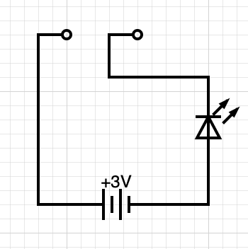
Our first lecture with Liza ended with a challenge to make a simple Continuity sensor. We were provided with some basic materials.
Materials
- Waste Neoprene Fabric.
- Safety Pins for Connectors.
- An LED.
- Conductive Thread.
- Basic Sewing Kit.
I thought it would be a nice idea to make this in the shape of my heart. I grew a very quick outline of a human heart and designed the circuit to flow within the shape. I initially got my positive and negatives mixed up and also I kinda misunderstood the way the batery was connected to the safety pin. I had the bottom (negative) connected twice sewn underneath where the battery was connected instead of connecting the underneath to the negative and the pin to the positive. When I figurged that out and fixed the connections it worked perfectly. I am super happy with the result.
Digital and Analogue Sensors
Firstly there is a difference between an analog and a digital sensor. It seems like its the other way round as it should be to me cause of the way we talk about analog and digtal in the modern world but of course it makes sense.
Digital = Binary / 1 0 1 0 1 0 / On or Off Analog = A range of values between 2 points
For this project we were tasked with making both. I had just left to go to Reykjavik when I was told that we needed one of each for the lecture on Friday, so this was the point I realised I hadn´t been given the Velostat fabric that I could make an analog switch.
I tried various ways of making some form of potentiometer in the house using various verisions of knitting my conductive thread on its own, with retro reflective, with thick wool, stuffing it with felt etc.... The values always came out digital. On or Off.
At this point a had a load oF tiny knitted conductive bits and not alot of materials left so I just decided to frankenstein something together digitally to try and make something interesting.
5 Tone Digital Switch and Voltage Divider
Materials
- Old Machine Embroidery Sample from 2005
- Waste Pleather from my re-upholstered kitchen chairs
- Conductive Fabric
- Conductive Tape
- Conductive Thread
- A Buzzer
- 3 Resistors of different resistance values
- A Light Dependant Resistor
- 9V Batery and connector
- A Bread Board
- A Voltmeter
- Basic Sewing Kit
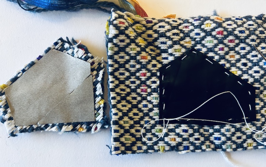
Base Material
For the base of my sensor I looked through some old samples that were just lying around my house with no purpose for years. I found this embroidery that I had made on an old sample I made from the inner facing of a mans tailored suit jacket. It had obvious places that look like keys or buttons. The fabric was pretty old and worn in the parts that were not embroidered so for ease I found some off cut pleather traced the shape of the fabric and hand stitched it underneath to strenghen the piece. I decided to but the softer side down for a grippier hold.
Connector
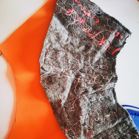
Using all the little bits of kniited and crochet conductive materials I had made trying to make an analog sensor I sewed then to together to look like a kinda weird pink finger. it was then I figure that I would use this as a connecting piece to close the circuit I was trying to make.
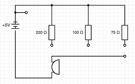
Circuit Design
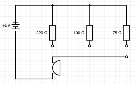
Firstly I needed to see if I could make a circuit. My partner had some bits in the house for making basic electonics as he likes to construct Modular Synths as a hobby. So I had a bread board and made a very basic circuit with an LED and a resistor. I then found a box of weird sensors and tried to get those working but in tyipcal me style I was running before walking. I decided to test out a simple horible screachy buzzer. This works in a similar way to an LED but instead of a light output its a sound output. As I was trying to play with the notion of being able to make a "kinda" analogue system I figured if you play with the resistance values of the current flowing into the buzzer then you should get different tones. I tested the circuit below on the breadboard and it worked.
Now how do you make it soft....
Circuit Construction
Having limited conductive materials available was actually an interesting problem. It informed my construction choices as I knew I needed to keep the positive side away from the negative so using the conductive fabric that was only conductive on one side on the bottom face of the piece would decrease the chances of an accidental short circuit when using the piece. As I only had a limited amount and I knew I needed 3 pieces for the "finger" to "touch" I cut the remaining amount into long strips to connect the finger, sown with conductive thread to the bottom side to the bottom of the buzzer. I actually had a problem here for a while getting the buzzer to connect. I had just poked the short connector through the fabric and underneath the conductive fabric which was only touching the adhesive side. I had to sew the conductive fabric back onto the top side to connect it instead so my design feature actually became a bit of a problem.
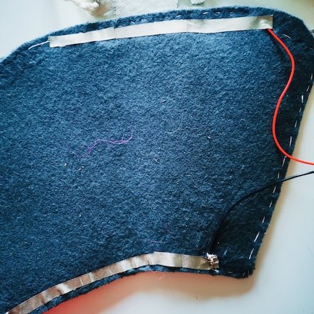
I stiched most of the design in conductive thread starting at the battery along the bottom edge with the resistors attached between the botton line and the touch pad where the finger would connect the circuit. I started out with 3 points using the 3 different resistance values. It took a wee while to get everything working (thank you small buzzer connection wires) but eventually it almost always gave 3 different tones.
The 4th Tone
I then realised I could create a 4th tone from having no resistance at all. I stiched an extra line from the bottom of the last connection and ran it up to a place where the finger could connect to it. As I had no more conductive fabric left I used the conductive foil for the connection and that worked like a charm.
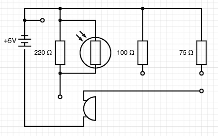
Analog 5th Tones
As I had tried and failed to make an analog sensor without the Velostat material I thought about how I could make something with this set up that would vary the values without it. I found a LDR, Light Dependant Resistor in my box of random bits so I started to play with is on the bread board using a buzzer and different resistors to see if I could get and noticable change in tone. It was very faint but it worked. I found that the best resistor that worked with it was the 220 I had already inbedded to get my highest tone so all I would need to do was to stitch this LDR in parallel to the resistor and in theory if the finger was touched down on the connector attached you could vary the tone slightly. This also worked albeit very slightly but TBH I was estatic with the outcome.
Arduino
Due to my hospital admission I stayed an extra day in Reykjavik so I followed as much as I could and actually cause I had started to figure out the bread board with the 5 tones I followed most of it. I feel that there is so much more I need to learn with Arduino but I was happy to use the codes that Emma provided to follow the first part of the tutorial. I had also tried to hook up a variable sensor on it but that didn´t work properly.
The Hardware
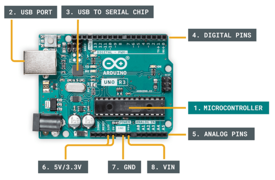
- Microcontroller - A tiny computer that acts like the brain of the operation.
- USB Port - Connects the computer to the board.
- USB to Serial Chip - Translates data. Makes it possible to program the board.
- Digital Pins - Use digital logic (0,1 or LOW/HIGH).
- Analog Pins - Can read analog values in 10bit (0-1023).
- 5V/3.3V - Used to power components.
- GND - Ground or negative.
- VIN - To connect to external power supplies.
The Software
The Arduino Integrated Development Environment (IDE) is the main text editing program used for Arduino programming. It is where you imput code before uploading it to the board you want to program. Arduino code is referred to as sketches. After downloading I connected the board via USB and opened the sketch blink.io that can be found in the file menu under examples and 01. basics. This sketch allows you to check everything is working by making the on board LED near pin 13 blink. It blinked so I know it read the code.
Next we set up a very simple LED circuit with a 220ohm resistor and tested two sketches from Emma Pareschi just to turn on an LED and to make it blink. by varying the delays in the software we were able to control the timings of the blink.
Analog Sensor
I finally got my hands on some velostat so I made a very simple analog sensor by placing it between two pieces of conductive fabric and stitching it all together.
Analog Read
Finally using the code 05_read_AnalogSensor from Emma Pareschi I was able to see the varying values created from the pressure on the sensor in the serial monitor. The serial monitor alows you to monitor whats going on inside the board.
The Code
Emma Pareschi - Fabricademy 2022/2023.
int analog_sensor_pin = A0;
int analog_sensor_value = 0;
void setup() {
pinMode(analog_sensor_pin, INPUT);
Serial.begin(9600);
}
void loop() {
analog_sensor_value = analogRead(analog_sensor_pin);
Serial.println(analog_sensor_value);
delay(100);
}
- Using the AO pin to put the data in as analog_sensor_pin in a value of 0 and as an Input so its reading the data from the sensor rather than outputing.
- The command Serial.begin(9600;) you can see the numbers in a lower value.
- In the loop analog_sensor_value = analogRead(analog_sensor_pin); you read the voltage of the pin sensor
- Serial.println(analog_sensor_value); prints the varying values on the serial monitor so you can see them.
- The delay(100); also slows the information down so i can be read easily.