Sound
Stethoscope
After researching many ways of listening to the heart the most obvious way to listen directly was using the old fashioned Stethoscope Its fascinating that this instrument is relately simple in design and has not changed much in many years and yet it is still widely used today in medicine. It has no electronics in it, just using a diagram on a bell section to send sound vibrations for a medical professional to auscultate or listen to the heart of a patient through rubber tubbing connected to an earpiece. After researching buying one and realising the proper ones can cost $100 I wondered if I could just make one myself. Thats when I came across the Glia Stethoscope
Glia Open Source Stethoscope Project
I was really impressed with this project that makes open source medical equipment for conflict zones and to cut down socioeconomic barriers to medical personal. Dr. Tarek Loubani founded Glia after working in Gaza and seeing a lack of these in the hospitals there. The prototypes were inspired by the classic 1968 Littmann stethoscope design. I decided to print one myself so I could start the process of listening to my heart.
The Print
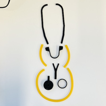
The making seemed straight forward so I downloaded the files from the GITHUB link here. After reading the documentation I split the print into 2 parts as it said that the ear tubes and Y-piece may need a brim. NOTE this caused problems with fit in construction so I do not reccommend doing this. The other files I printed with a skirt instead.
- It important the infill is at 100%
- The reccomended filament is PETG or ABS for durability but I just use PLA as its only a working prototype and not for medical usage.
Print 1
- 2x Ear Tubes (eartube.stl)
- 1x Y-Piece (y_piece.stl)
Print 2
- 1x Stethoscope Head (head.stl)
- 1x Spring (spring.stl)
- 1x Ring (ring.stl)
Printer Settings
Fillament Type - Generic PLA
Size - Normal 0.3mm
Layer Height -0.2mm
Top/Bottom Thickness - 0.8
Top/Bottom Layers - 3
Infill - 100%
Infill Pattern - Grid
Printing Temperature - 220%
Build Plate Temperature - 60°
Print Speed 60mm/s
Build Plate Adesion - brim (print 1) or Skirt (print 2)
Construction
Once I had the printed pieces I found and prepared the non printed pieces.
We had some large gold silicon tubing lying round the lab. I´m guessing its roughly 12mm wide, 8mm inner.
- Cut 40cm for the connection from Y-piece to head.
- Cut 2x 10cm for the connection from earpieces to Y-piece.
I also found a document folder that looks very similar to this and from this..
- Cut 1x 4cm diameter circle from document folder.
Glia provide a link to their very simple construction video below.
Issues
The stethoscope was actually more difficult to assemble that you would think. The parts printed with the brim even with it having been removed didn´t fit well at all. I had to sand them down to get to fit in the right way.
Also the ring didn´t fit on the head. I tried heating it and sanding it but eventually i reprinted another one increasing the scale by 1mm. This was slightly too big but I sealed it with electrical tape and its good enough.
I don´t have any spare headphone earbuds and it is definately uncomfortable to wear these in you ears. I would reccommend also increasing the scale of the spring if you have a bigger head, which I now believe I have.
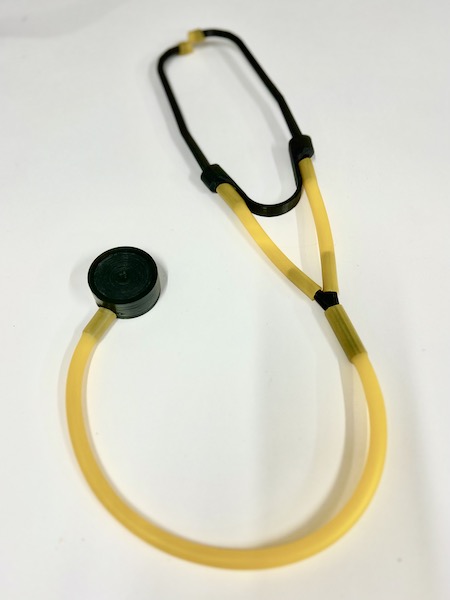
Final Prototype
So it works. I can hear my heart through the headphones so success. I will have to experiment with diaphragms I think to get a clear sound every time. It definately needs a little refinement but its a great start. I currently have a baloon stretched over the top and I feel it gives good clarity of sound.
Stethosynth
My first exploration in electronics for this final project is hacking my Gila OS Stethoscope that I just lovingly 3D printed. I needed to see if I could detect heart sounds with it so I removed the lower tube and head from the Y-piece of the stethoscope and attached a large voice detection module I had in my kit to the other end of the tube, where the Y-piece had been.
LED Test
First I wanted to see if it detctected anything at all so I set a simple LED circuit and its certainly doing something which tells me there is a signal coming from the head at least.
The Code
THE CODE
int sensorPin = A0; // Input from sound detector
int ledPin = 13; // Pin for the LED
int sensorValue = 0; // Variable to store the value coming from the sensor

void setup ()
{
pinMode (ledPin, OUTPUT);
Serial.begin (9600);
}

void loop ()
{
sensorValue = analogRead (sensorPin);
digitalWrite (ledPin, HIGH);
delay (sensorValue);
digitalWrite (ledPin, LOW);
delay (sensorValue);
Serial.println (sensorValue, DEC);
}
Speaker Test
So could I play my heart sounds through a speaker? was my next question. I knew it was being detected so I got out the fabric embedded 8ohm speaker I had made for Wearables Week. I am so glad I made it modular in the end so I can use it for prototyping here. Next I consulted my new best pal Chat GBT, an AI that can be used for debugging code. Its honestly AMAZING and I cant wait to welcome our new robot overlords. Anyway, It gave me the idea of assigning the tone function to the output so it could be heard on the speaker. I was very happy when it all worked.
The Code
int sensorPin = A0; // Input pin for the sound sensor.
int Speaker = 13; // Output for speaker.
int sensorValue = 0; // Variable for Value coming from the sensor

void setup ()
{
  pinMode (Speaker, OUTPUT);
  Serial.begin (9600);
}
void loop ()
{
  sensorValue = analogRead (sensorPin);
  tone(13, sensorValue);  // play the tone on pin 13
  delay (sensorValue);
  noTone(13);  // stop the tone
  delay (sensorValue);
  Serial.println (sensorValue, DEC);
}
Stethosynth Ideas
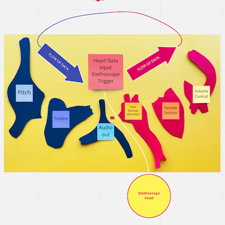
After testing the stethoscope it became very clear that getting a nice clear heartsound with the set up I had was going to be pretty much impossible. The cheap sound detector was never gonna cut it so I definately need to invest in a better microphone set up. My intial thoughts were to use the sound of the heartbeat and play with that in some form to create new musical forms but after these experiments and talking with my long suffering partner Nonni, (he likes modular synths), we thought about the use of this heart sound as a trigger. This would mean simply that the heartbeat would trigger a sample of some sort and that would be messed with in the rest of the piece. GENIUS. This really helps to remove the need of the wearer to get a good clean sound signal. The wearer would just have to detect the beat and the rest of the party is ON!!!
I think there are 2 areas of possible research for this method. taking into account the work I am doing in the form of the piece.
-
Heart as Sample Selector - A discrete way of selecting between several samples to be used as the basic sound of the synthesizer
-
Heart as a Wavetable - Using a wavetable it is possible to algorithmically morph between several basic sounds continuously to create the basic sound of the synthesizer.
Using one of these 2 options the rest of the piece can look at the following that can interact with the user.
-
Pitch - Can be quantised to notes or free.
-
Timbre Control - Different controllers to continuously modify parameters of the sound engine, such as the filter cut-off, filter resonance and overdrive.
-
Volume - Controller to change the volume and decay of the sound to essentially control the volume envelope of the synthesizer.
Other Possible Modules/Controllers -
- Delay and Reverb effects.
- Rhythm generator (with heart beat as the main clock)
- Octave jumping for pitch
- Switch between free and quantised pitch.
- LFO(s) to automatically change parameters. Controls for frequency and magnitude.
Prototyping
For the final sound design I have ordered a Teensy 4.0 with a compatable audio shield that will come in mid Feburary. The reason I chose this development board is because the Teensy is used extensively in the hardware of modular synths which quintesentially this project is kinda becoming. After watching these tutorials from the youtube channel Notes and Volts, I figured that this would be an, well, easyish way of getting a very basic synth together for the project.
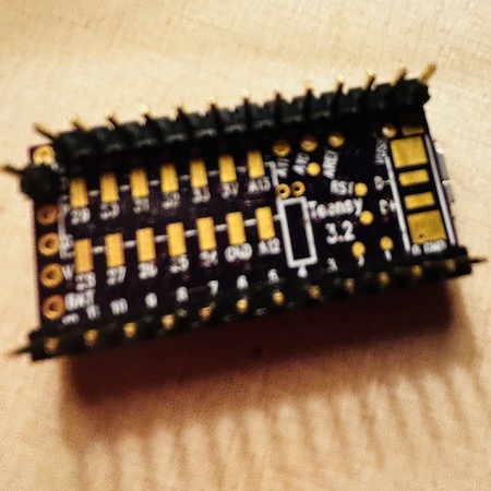
As I am waiting for the 4.0, luckily my modular synth geek partner Nonni had a spare Teensy 3.2 lying around so we could test the concept of getting a programable thing that might make a beep noise or two at least.
Hardware
First things first. Know your hardware! A rule I made for myself that I think will serve me well.
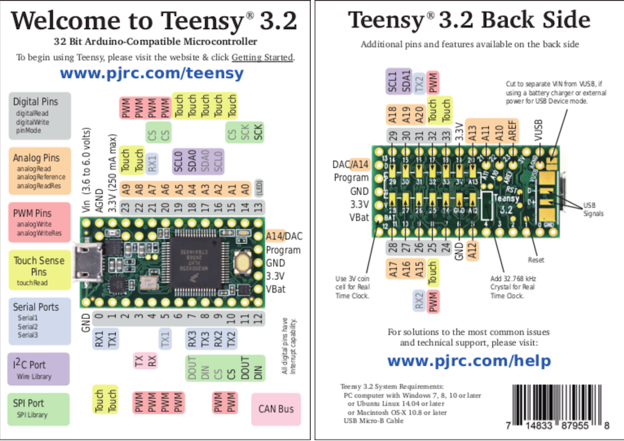
Its actually pretty difficult to see the pins on the Teensy so the working diagram that came with the board is a constant reference tool.
- Below is the diagram for the Teensy 3.2.
As this is a prototype without all of the funtions available it was a bit confusing where to start. The audio shield for the Teensy comes with some built in features that are not available on a plain old Teensy it was initially a bit of a problem as you are trying to navigate the different Teensy audio library functions. With the extra shield, the Teensy audio library is used as an inbuilt software toolkit for building audio projects. It is capable of polyphonic playback, recording, synthesis, analysis, effects, filtering and mixing capacities with multiple simultaneous inputs & outputs, and flexible internal signal routing.
- Here is a tutorial from the library developer that walks through many of the functions available with the libraries.
The first thing that we tried to do was to play the USB audio just through the computer as you would be able to from the audio shield but this didnt work. Then the next step was to use the DAC(digital to analogue converter) or DAC/A14 pin even though the output of this audio is not of high quality (12bits). with these limitations however, this is the most important output on the development board for output. DAC is a fundamental key to unlocking the convenience of digital music as it converts digital information into analogue signals that are intelligible to speakers, headphones and the human ear. They all need an analogue waveform. Without a DAC, digital music is nothing but a sizeable collection of “0s and 1s” that makes sense only within the digital domain. I remembered watching a video again from Notes and Volts showing the differences between the Teensy 3.2 and the Teensy 3.2 with the audio shield. This gave me a good grounding in how to do the initial set up with the bare development board.
Following this video, I needed to make this prototype usable and easy to work with. As the board comes completely naked, the first thing you need to do is solder on headers to the pins to add this to a breadboard. As this prototype is not going to be embedded into a soft interface, the header pins were soldered onto the available input and output pins. The most important pin on the board for my purposes is the DAC/A14 pin As this pin is on the end of the Teensy when the pins were soldered on it was necessary to sacrifice pin 13 in order to attach a singular pin to the DAC pin as you can see in the picture of the final picture below. The pins were attached while on the breadboard to ensure they were soldered on straight. There is a possibilty that the breadboard can be damaged while doing this but the ones I have are super cheap so I took the risk.
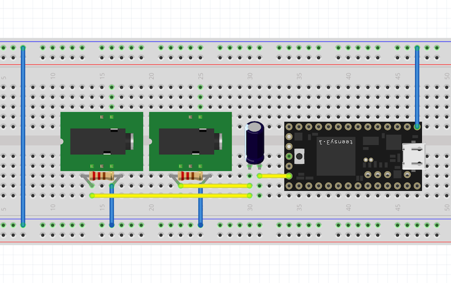
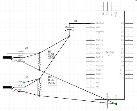
Prototype Board
Once the Teensy was connected and it was tested for power, it was now necessary to make a basic set up board to test any code. The board had to have a speaker output and an headphone output (as I quite like my flatmates and I´m working from home). The audio jacks used were a black Thonkicon 3.5 mono jack for the speaker output and a green Thonkicon 3.5 stereo jack for the headphones. These do not show in the circuit software but the basic idea is below.
Teensyduino
Now its time to play. First you need to download 2 things Teensyduino is a software add on for Arduino that allows you to easily run sketches that you have designed on Arduino IDE on the Teensy. The other thing you need is the Teensy Loader Application that communicates with your Teensy board so you can download new programs and run them. The installation is very simple and I thought that best way to test if the set up was to get a sample code working. Its a code from the audio library in Teensyduino adapted from pass through mono. You can hear this delightful noise here.
The Code
Here is the code used for the above sample with some notes added to help with the debugging of future add ons.
#include <Audio.h>
#include <Wire.h>
#include <SPI.h>
#include <SD.h>
#include <SerialFlash.h>

// Arduino Audio library routing
AudioSynthWaveform       waveform1;
AudioOutputAnalog        dac1; // Internal Teensy DAC for now. To be replaced in future versions.
AudioConnection          patchCord3(waveform1, dac1);

void setup() {
  // Initialize the serial bus for debuging.
  //Serial.begin(9600);

  // Assign the neccesary audio memory.
  AudioMemory(1); // For a simple application, 1 block should be enough.

  // Initialize the oscillator to a sawtooth waveform and 440Hz (A3).
  waveform1.begin(WAVEFORM_SAWTOOTH);
  waveform1.amplitude(0.9); // For the initial prototype, setting the output volume here.
  waveform1.frequency(440);
}

void loop() {
  // In lieu of controller input, scan the oscillators frequency.
  for(int freq=50; freq<=5000; freq++)
  {
    waveform1.frequency(freq);
    delay(1);
    // Note the interesting sound artifacts, most likely due to low resolution of the teensys 12 bit DAC.
  }
}
Volume Envelope
Now theres a functional basic code that works its time to have a look at developing an envelope generator. Envelope generators are common tools in modular synthesis as they control different stages of a sound using the attack (beginning build up), decay(length of time the frequency and harmonics remain at their peak loudness before they start to disappear), sustain (sets the steady amplitude level produced when triggered) and release (sets the time it takes for the sound to decay from the sustain level to an amplitude of 0 when the trigger is released). This is also known as the abbreviation ADSR. Here you can start to play with certain parameters that could be interesting to control given a certain trigger such as the heart beat. for this example its been configured in an attack decay (AD) setup.
The Code
#include <Audio.h>
#include <Wire.h>
#include <SPI.h>
#include <SD.h>
#include <SerialFlash.h>

// Arduino Audio library routing
//AudioSynthWaveform       waveform1;
//AudioOutputAnalog        dac1; // Internal Teensy DAC for now. To be replaced in future versions.
//AudioConnection          patchCord3(waveform1, dac1);

AudioSynthWaveform       waveform1; // The basic sound generating oscillator.
AudioEffectEnvelope      envelope1; // Envelope, controls the loudness and character of the sound hits.
AudioOutputAnalog        dac1; // Internal Teensy DAC for now. To be replaced in future versions.
AudioConnection          patchCord1(waveform1, envelope1); // Connect the oscillator to the envelope.
AudioConnection          patchCord2(envelope1, dac1); // Connect the envelope to the output/DAC.

// Parameters that would be interesting to have externally controlled.
int attack = 100; // [ms] Onset of the sound, decides how "percussive" it is.
int decay = 200; // [ms] Decay of the sound, decides the "lifetime" of each hit.
int frequency = 440; // [Hz] The pitch/note of the oscillator. Default: A3 @ 440Hz.

void setup() {
  // Initialize the serial bus for debuging.
  Serial.begin(9600);

  // Assign the neccesary audio memory.
  AudioMemory(10); // Check AudioMemoryUsageMax() to set this appropriately.

  // Initialize the oscillator to a sawtooth waveform and 440Hz (A3).
  waveform1.begin(WAVEFORM_SAWTOOTH);
  waveform1.amplitude(0.9); // For the initial prototype, setting the output volume here.
  waveform1.frequency(frequency);

  // Initialize the envelope parameters. Using an Attack-Decay (AD) setup.
  envelope1.attack(attack);
  envelope1.hold(0);
  envelope1.decay(decay);
  envelope1.sustain(0);
  envelope1.release(1);
}

void loop() {
  // In lieu of controller input, scan the oscillators frequency.
  for(int freq=50; freq<=5000; freq=freq*2)
  {
    waveform1.frequency(freq);
    envelope1.noteOn();
    delay(1000);
    envelope1.noteOff();
    delay(100);
    Serial.println(freq);
    // Note the interesting sound artifacts, most likely due to low resolution of the teensys 12 bit DAC.
  }
}
Capacitive Sensor Controller
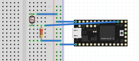
Now that we have the code for this basic incarnation of a synth its time to see if it works with external controllers. I went through all the sensors from previous projects and decided to do the first test with a capacitive sensor. The one I am using here is one that Louise actually made as its a bit more robust in design than the one I had made before. The theory is that now I have this basic undestanding of how the synth will work, I can apply it to different sensors in different chambers to allow the wearer to interact with the sound. A capacitive sensor is good in this respect as it works in an analogue way through touch. In this test 2 touch pads on the capacitive sensor are connected using large resistors of 560kohms. One pad is assigned to pins 16 and 15 and is used to change the oscillator frequency, in this case making the note sound higher. The other pad is assigned to pins 15 and 14 and is used to control the envelope decay making the note longer. I´ve added a rough schematic below. Its hard to show the exact wiring all nice and neat as the software Fritzing I have just started using only has a Teensy 3.0 so I´ve erm customised the diagram a bit.
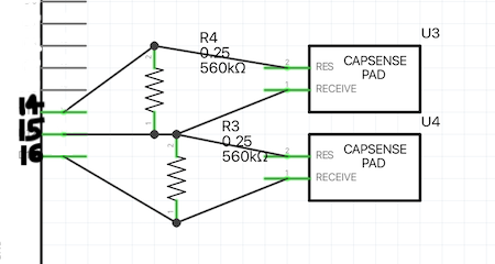
- Below you can hear the changes this makes and also how it affects the sound when you press both together.
The Code
#include <Audio.h>
#include <Wire.h>
#include <SPI.h>
#include <SD.h>
#include <SerialFlash.h>

#include <CapacitiveSensor.h>

// Set up the Capacitive Sensors.
CapacitiveSensor   cs_15_16 = CapacitiveSensor(15,16); // 560k resistor between pins 15 & 16, pin 16 is sensor pin.
CapacitiveSensor   cs_15_14 = CapacitiveSensor(15,14); // 560k resistor between pins 15 & 14, pin 14 is sensor pin.
// TODO: Make an array of the sensors

// Arduino Audio library routing
AudioSynthWaveform       waveform1; // The basic sound generating oscillator.
AudioEffectEnvelope      envelope1; // Envelope, controls the loudness and character of the sound hits.
AudioOutputAnalog        dac1; // Internal Teensy DAC for now. To be replaced in future versions.
AudioConnection          patchCord1(waveform1, envelope1); // Connect the oscillator to the envelope.
AudioConnection          patchCord2(envelope1, dac1); // Connect the envelope to the output/DAC.

// Parameters that would be interesting to have externally controlled.
int attack_init = 100; // [ms] Onset of the sound, decides how "percussive" it is.
int decay_init = 200; // [ms] Decay of the sound, decides the "lifetime" of each hit.
int frequency_init = 55; // [Hz] The pitch/note of the oscillator. Default: A1 @ 55Hz.

void setup() {
  // Initialize the serial bus for debuging.
  Serial.begin(9600);

  // Assign the neccesary audio memory.
  AudioMemory(10); // Check AudioMemoryUsageMax() to set this appropriately.

  // Initialize the oscillator to a sawtooth waveform and 440Hz (A3).
  waveform1.begin(WAVEFORM_SAWTOOTH);
  waveform1.amplitude(0.9); // For the initial prototype, setting the output volume here.
  waveform1.frequency(frequency_init);

  // Initialize the envelope parameters. Using an Attack-Decay (AD) setup.
  envelope1.attack(attack_init);
  envelope1.hold(0);
  envelope1.decay(decay_init);
  envelope1.sustain(0);
  envelope1.release(1);

  // Capacitive stuff
  cs_15_14.set_CS_AutocaL_Millis(0xFFFFFFFF); // turn off autocalibrate on channel 15-14
  cs_15_16.set_CS_AutocaL_Millis(0xFFFFFFFF); // turn off autocalibrate on channel 15-16
}

void loop() {
  waveform1.frequency(getFrequency());
  envelope1.decay(getDecay());
  envelope1.noteOn();

//  Serial.print(cap1);
//  Serial.print("\t");
//  Serial.print(cap2);
//  Serial.print("\t");
//  Serial.println(freq);

  delay(1000);
  envelope1.noteOff();
  delay(100);
}

int getDecay(){
  int cap1_value = cs_15_16.capacitiveSensor(30); // NB: Why 30???
  return decay_init + cap1_value / 5;
}

int getFrequency(){
  int cap2_value = cs_15_14.capacitiveSensor(30);
  return frequency_init + cap2_value / 10;
}
West Side East Side
As I was talking to my partner about this he was telling me some interesting facts about synthesis. I always thought the east side, west side thing was a 90s hip hop invention but its also a thing when talking about the increasingly popular usage of modular synths, with sound sources, sound manipulators and modulators controling individual aspects of the generated sound. Its a fascinating side research that you can read more about here. In this case so far the program is using the "East coast" style of synthesis or subtractive synthesis. This consists of a harmonically rich waveform (such as a sawtooth or square) that is then filtered to produce the final sound. This synth design is such that it is easy to add further controllers to manipulate the sound but as I am a complete newbie in music and programming I am working with the easiest. So lets but a filter on it.
LFO
Lets start this off with a bit of classic electronica, LFO by LFO cause its a great track.
An LFO or Low-frequency oscillation is a low electronic frequency that creates a rhythmic pulse or sweep. This is used in this instance to control the filter although it has many uses in synthesis. As I was testing this parameter I also wanted to get something that was starting to sound more like a heartbeat to see how the filter would behave. This was acheived by playing around with the envelope attack to create a psuedo lub dub sound as you can hear below.
The Code
#include <Audio.h>
#include <Wire.h>
#include <SPI.h>
#include <SD.h>
#include <SerialFlash.h>

#include <CapacitiveSensor.h>

// Set up the Capacitive Sensors.
CapacitiveSensor   cs_15_16 = CapacitiveSensor(15,16); // 560k resistor between pins 15 & 16, pin 16 is sensor pin.
CapacitiveSensor   cs_15_14 = CapacitiveSensor(15,14); // 560k resistor between pins 15 & 14, pin 14 is sensor pin.
// TODO: Make an array of the sensors

// Arduino Audio library routing
//AudioSynthWaveform       waveform1; // The basic sound generating oscillator.
//AudioEffectEnvelope      envelope1; // Envelope, controls the loudness and character of the sound hits.
//AudioOutputAnalog        dac1; // Internal Teensy DAC for now. To be replaced in future versions.
//AudioConnection          patchCord1(waveform1, envelope1); // Connect the oscillator to the envelope.
//AudioConnection          patchCord2(envelope1, dac1); // Connect the envelope to the output/DAC.

// GUItool: begin automatically generated code
AudioSynthWaveform       waveform1;      //xy=95,319
AudioSynthWaveform       lfo1;      //xy=166,447
AudioFilterStateVariable filter1;        //xy=267,323
AudioEffectEnvelope      envelope1;      //xy=426,323
AudioOutputAnalog        dac1;           //xy=596,321
AudioConnection          patchCord1(waveform1, 0, filter1, 0);
AudioConnection          patchCord2(lfo1, 0, filter1, 1);
AudioConnection          patchCord3(filter1, 0, envelope1, 0);
AudioConnection          patchCord4(envelope1, dac1);
// GUItool: end automatically generated code

// Parameters that would be interesting to have externally controlled.
int attack_init = 100; // [ms] Onset of the sound, decides how "percussive" it is.
int decay_init = 100; // [ms] Decay of the sound, decides the "lifetime" of each hit.
int frequency_init = 550; // [Hz] The pitch/note of the oscillator. Default: A1 @ 55Hz.
int lfo_frequency_init = 10; // NYI: Do it as a ratio of the actual heartbeat?

bool beat_started = false;

void setup() {
  // Initialize the serial bus for debuging.
  Serial.begin(9600);

  // Assign the neccesary audio memory.
  AudioMemory(30); // Check AudioMemoryUsageMax() to set this appropriately.

  // Initialize the oscillator to a sawtooth waveform and 440Hz (A3).
  waveform1.begin(WAVEFORM_SAWTOOTH);
  waveform1.amplitude(0.9); // For the initial prototype, setting the output volume here.
  waveform1.frequency(frequency_init);

  // Initialize the envelope parameters. Using an Attack-Decay (AD) setup.
  envelope1.attack(attack_init);
  envelope1.hold(0);
  envelope1.decay(decay_init);
  envelope1.sustain(0);
  envelope1.release(1);


  filter1.resonance(0.707);    // "lfo2" waveform overrides this setting
  filter1.frequency(800);     // "lfo1" modifies this 800 Hz setting
  filter1.octaveControl(2.6); // up 2.6 octaves (4850 Hz) & down 2.6 octaves (132 Hz)

  lfo1.frequency(lfo_frequency_init);
  lfo1.amplitude(0.09);
  lfo1.phase(270);
  lfo1.begin(WAVEFORM_TRIANGLE);

  // Capacitive stuff
  cs_15_14.set_CS_AutocaL_Millis(0xFFFFFFFF); // turn off autocalibrate on channel 15-14
  cs_15_16.set_CS_AutocaL_Millis(0xFFFFFFFF); // turn off autocalibrate on channel 15-16
}

void loop() {
  waveform1.frequency(getFrequency());
  envelope1.decay(getDecay());
  lfo1.frequency(getLFOFrequency());


//  Serial.print(cap1);
//  Serial.print("\t");
//  Serial.print(cap2);
//  Serial.print("\t");
//  Serial.println(freq);

// to create psuedo heartbeat
  if(beat_started){
    envelope1.attack(attack_init + 150);
    envelope1.noteOn();
    delay(600);
    beat_started = false;
  }
  else{
    envelope1.attack(attack_init - 50);
    envelope1.noteOn();
    delay(400);
    beat_started = true;
  }
  //delay(1000);
  envelope1.noteOff();
  //delay(100);
}

int getDecay(){
  int cap1_value = cs_15_16.capacitiveSensor(30); // NB: Why 30???
  return decay_init + cap1_value / 5;
}

int getFrequency(){
  int cap2_value = cs_15_14.capacitiveSensor(30);
  return frequency_init + cap2_value / 10;
}

int getLFOFrequency(){
  int cap1_value = cs_15_16.capacitiveSensor(30); // NB: Why 30???
  return lfo_frequency_init + log(cap1_value)*2;
}°
Prototyping Part 2
All my electronics arrived in Reykjavik so It was time to get on with prototyping on the actual board that I would be using. I started planning and testing diferent interfaces to work with once I had the final shapes sort of nailed down. When I was home we were playing with my partners extensive modular synth set up when we came across the Yowler from the super fun Cat Full of Ghost Electronics. When this was purchased on kickstarter it has a really fun way of working with 4 LDRs and a bunch of other components to make super weird noises. The later version as you can see in the video below has an added sheild over the LDRs that has LEDs emebeded on the back to further mess with the sound. Playing with this weird wee toy made us think about the possiblities of playing with LDRs or Light Dependant Resistorsin the Hearty Party.
Light Dependent Resistors
The idea is to return to the very first e-textile project I did and basically create a voltage divider circuit but this time using the LDRs instead of using digital touch. LDRs are used in voltage divider circuits such as lights to turn off in light and on in the dark. At a low light intensity, LDRs have a high resistance so the output voltage is high. As the light gets brighter, The resistance, and therefore output voltage, decrease. Initially, using a wave form, the values read from the LDR voltage divider are used to control the loudness of each sample. It was also important to set an initial value to be read at start-up. This is to establish the ambient light conditions to enable you to scale the values read from the LDRs.
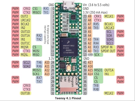
At this point we managed to buy a Teensy 4.1 with Audio Shield from a mate locally, (cheers Hallmar). This board already soldered together so its easy to just get started on the programming. It has considerably more pins on it compared to the 4.0 but its also a load bigger so it depends how much functionallty needed as to which one would be best for the project. Below you can see the pinout table for the 4.1 without the audio shield. I also tried to make a simple schematic in Fritzing but they only have Teensys up to 3.0 which is quite different but I hope it give the idea of the set up.
- Below you can see (and hear) the very first LDR circuit, as I call it, toy. It was so much fun to play even though its just one LDR. This is when I knew this was an idea worth exploring further.
When the LDR is entirely lit, its resistance value drops significantly and can reach close to 0Ω. When the LDR is in the dark it’s resistance value gets close to it being an insulator. When compared to the static resistor in a voltage divider circuit, a continuous voltage value between GND and V+ (0V and 3.3V) can be read on an input pin of the Teensy therefore creating the sensor effect. The read value is read as 10bit, 0 - 1023. 1023 represents a dark LDR and 0 an LDR in full light. Of course If you change the circuit to be the other way round you get the opposite effect. You can also change the values in the program so the 1023 can represent a light LDR.
Its worth noting here that all the LDRs lying around in the house are fairly different so its vital to test them as choosing similar ones is important. We found some of them consider light coming in laterally while others don´t. I found that the ones that had more of an orange tinge around the side edges tended to let more light in through the sides for some reason.
On startup the value is again read as a baseline for the ambient conditions. This function, it turns out, is way more important in dark situations as it can be very unpredictable when switched on otherwise. The startup value is scaled to be between 0 and 1. ldr_ratio = (V_in - V_0) / (1023 - V_0). This ratio can then be used anywhere in software to influence the program.
In the next circuit with one more LDR added in and you can really see the functionlity increase greatly with the 2 control possibilties. At this point it felt like I was playing the theramin which was actually amazingly good fun.
As there are 4 chambers in the prototype I´m working on, 4 of these voltage divider circuits were installed to represent these chambers. First using laboratory conditions (i.e. bright environment), with static resistances of 10kΩ.
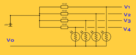
- The 10kΩ resistance level eventually proved too low for further experiments in more realistic settings. After testing multiple resistors ranging from 10kΩ to 1MΩ, it was decided that 150kΩ provided the best performance in multiple light scenarios.
Stethosynth. An Update
As these experiments have continued as has my journey in trying to isolate my heart beat without the use of sticky EKG patches or terrible ultrared pulse detectors. After all the effort of making my own stethoscope it turned out we had a very stethoscope looking thing called the Husoscope by Crank Surgeon in the house all along.
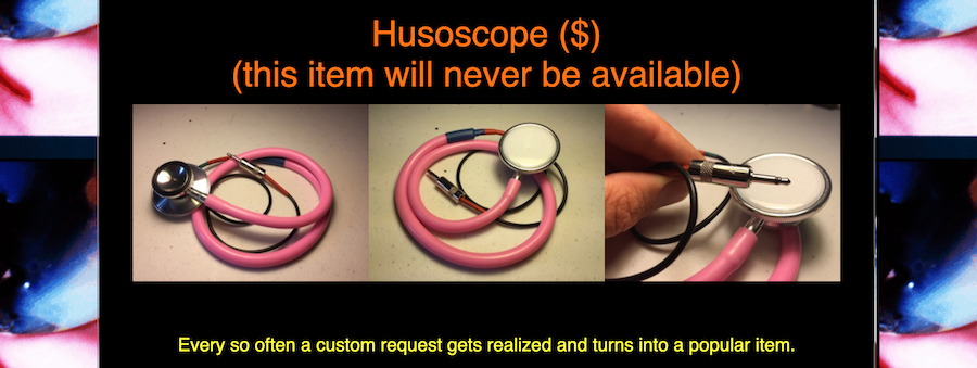
The Husoscope is basically a lo-fi microphone with a classic medical stethoscope head hooked up to an electret microphone. So basically exactly the same thing I was trying to build. As you can hear on this recording its descibed as "making one’s voice sound like a circus barker trapped inside an ancient gramophone."
Well when we tested it this was completely true and although this made for an entertaining afternoon talking into it and trying to place it around the body, it worked pretty well as a contact mic or regular mic. it completely sucks at hearing the heart beat.
At this point I got my version out and tested it in the same way. placing a small electret microphone at the end of the long tubing and again talking into it and placing it around the body. Do you know the one I made actually worked better, even with the balloon diaphragm. Still pretty unreliable at attaining the heart beat though so at this point the idea of triggering it directly from the heart is being left to the last minute. If I can prove it works I will, later.
The Sounds of Myocardial Infarction
So now theres a working prototype with 4 LDRs I had an idea that instead of still trying to get the heart beat to trigger the synth to work. I thought it would be great to use different sounds of a heart attack, Myocardial Infarction. Its hard to find echocardiogram auscultation sounds of this but I found the below example from a medical sound library called Medzcool.
Using the open source audio software Audacity, 4 small samples from these sounds were created to apply to this circuit and uploaded to the Teensy by using the in-built SD card reader. These 4 samples of heart beats during different cardiac events loop continuously at zero volume. The LDR ratios control the volume of each sample. The volume of each or multiple sample(s) can be increased by covering the respective LDR. Here, a scaling function has been added to the code. This means that the volume is 0.0 until a threshold of 0.1 is reached, then the volume rises linearly until 1.0 is reached when the LDR ratio is at 0.5. Doing this ensures that the program maps the LDR ratios to be more user-friendly and sonically interesting.
The Code
#include <Audio.h> // List of Audio Libraries from the Teensy
#include <Wire.h>
#include <SPI.h>
#include <SD.h>
#include <SerialFlash.h>

AudioPlaySdWav           playWav0; // Play four WAV files from the SD card one after the other.
AudioPlaySdWav           playWav1;
AudioPlaySdWav           playWav2;
AudioPlaySdWav           playWav3;

AudioOutputI2S           audioOutput;

AudioMixer4              mix1;

AudioConnection          patchCord1(playWav0, 0, mix1, 0);
AudioConnection          patchCord2(playWav1, 0, mix1, 1);
AudioConnection          patchCord3(playWav2, 0, mix1, 2);
AudioConnection          patchCord4(playWav3, 0, mix1, 3);

AudioConnection          patchCord5(mix1, 0, audioOutput, 0);
AudioConnection          patchCord6(mix1, 0, audioOutput, 1);

AudioControlSGTL5000     sgtl5000_1;

// Use these with the Teensy Audio Shield
#define SDCARD_CS_PIN    10
#define SDCARD_MOSI_PIN  7
#define SDCARD_SCK_PIN   14

#define LDR_PIN0 A3
#define LDR_PIN1 A2
#define LDR_PIN2 A1
#define LDR_PIN3 A0
int ldr0 = 0;
int ldr1 = 0;
int ldr2 = 0;
int ldr3 = 0;
int ldr0_0 = 0;
int ldr1_0 = 0;
int ldr2_0 = 0;
int ldr3_0 = 0;

float mix_init = 0.0;

void setup() {
  Serial.begin(9600);

  // Audio connections require memory to work.  For more
  // detailed information, see the MemoryAndCpuUsage example
  AudioMemory(8);

  sgtl5000_1.enable();
  sgtl5000_1.volume(0.7);

  // Set the initial mix levels
  mix1.gain(0, mix_init);
  mix1.gain(1, mix_init);
  mix1.gain(2, mix_init);
  mix1.gain(3, mix_init);

  // Adding 10 to the initial values in order to emphasize the zero value at ambeint conditions.
  ldr0_0 = analogRead(LDR_PIN0) + 10;
  ldr1_0 = analogRead(LDR_PIN1) + 10;
  ldr2_0 = analogRead(LDR_PIN2) + 10;
  ldr3_0 = analogRead(LDR_PIN3) + 10;

  SPI.setMOSI(SDCARD_MOSI_PIN);
  SPI.setSCK(SDCARD_SCK_PIN);
  if (!(SD.begin(SDCARD_CS_PIN))) {
    // stop here, but print a message repetitively
    while (1) {
      Serial.println("Unable to access the SD card");
      delay(500);
    }
  }
}

void loop() {

  // Loop all the sounds.
  // BUG: There are some clicks. I think it's not clipping because of volume on the mixbus. Might be the samples.
  // NYI: Use a different library to be able to adjust the playback speed.
  if (!playWav0.isPlaying()) {
    playWav0.play("SOUNDS/BEAT-01.WAV");
  }
  if (!playWav1.isPlaying()) {
    playWav1.play("SOUNDS/BEAT-02.WAV");
  }
  if (!playWav2.isPlaying()) {
    playWav2.play("SOUNDS/BEAT-03.WAV");
  }
  if (!playWav3.isPlaying()) {
    playWav3.play("SOUNDS/BEAT-04.WAV");
  }

  // Continously read the LDR values as a ratio, scaled by the ambient value.
  float value0 = max(float(analogRead(LDR_PIN0) - ldr0_0) / float(1024 - ldr0_0), 0.0);
  float value1 = max(float(analogRead(LDR_PIN1) - ldr1_0) / float(1024 - ldr1_0), 0.0);
  float value2 = max(float(analogRead(LDR_PIN2) - ldr2_0) / float(1024 - ldr2_0), 0.0);
  float value3 = max(float(analogRead(LDR_PIN3) - ldr3_0) / float(1024 - ldr3_0), 0.0);

  mix1.gain(0, value0 * 0.6);
  mix1.gain(1, value1 * 0.6);
  mix1.gain(2, value2 * 0.6);
  mix1.gain(3, value3 * 0.6);
  }
  else {
    Serial.print(value0);
    Serial.print('\t');
    Serial.print(value1);
    Serial.print('\t');
    Serial.print(value2);
    Serial.print('\t');
    Serial.println(value3);
  }
}
Disco Mode
I thought it would be fun to have a secret mode to play with. So Elton mode was born.
I saw Elton John doing his farewell Goodbye Yellow Brick Road Tour in Leipzig 2 days before my heart attack so its been a personal representation of the event for me. We were super late to the concert so it was actually a very stressful experience but a great show. I wasn´t a masssive fan of Elton John in particular but he put on an amzing concert. Since the heart attack this song in particular has been following me around especially when I was in Cardiac Rehabilitation in the amazing facilty, Reykjalundur, Just outside of Reykjavik. This is why using this song to create the fun part of the hearty party made sense to me.
The idea was that if all the samples are played simultaneously by covering all the LDRs the program enters a mode where a small section of Elton John’s “Don’t go Breaking my Heart” loops. Instead of controlling volumes, the LDRs now control sonic characteristics of the sample being played. Using Audacity, a small 10 second loop of the song was created. Then through programming, the LDRs can control the reverb amount and reverb size of the sample rather than playing different samples as in the heartbeat sample. Using a very basic addition in the code we were able to get the prototype to work so that if no LDR is covered the sample plays regularly and if it reaches the end (approx 10s) the program exists "Elton" mode. The additional sample is added to the SD card and the basic code added to begin the mode is below.
  if (value0 > 0.5 and value1 > 0.5 and value2 > 0.5 and value3 > 0.5){
    Serial.println("Trigger Elton Mode!");
Granular Synthesis
Looking into interesting parmeters to play with in disco mode Nonni suggested to look at a technique called Granular Synthesis. Granular synthesisers take very small sections of the audio sample and manipulate their pitch and/or speed of playback. Using the inbuilt audio library its possible to start playing with this as you can see in the digital Electronics project from Anders Nordstrom above. In this disco mode it is just used simply to modify the pitch of the sample while maintaining its playback speed. As this sounds absolutly mental, the precise values of all thresholds and settings have all been left easily editable in the program. This is done so that adjustments can be made on-the-fly if ambient conditions are not favourable.
Elton Mode Development
Initially the audio effects were implemented in parallel, such that each one affected the original sound and they could all be played at the same time. In particular with the granular effects but this was quite frankly mental sounding and not sonically pleasing. As it was my intention to play this with other heart disease patients we decided that toning down the crazy noises might be in order. When the effects were re-implemented in series where the output of each goes into the input of the next you get a much more harmonius effect in general. Now the set up of sounds were defined I was able to allocate them to to different chambers.
The four final effects used are
- Granular freeze
- Granular pitch shift
- Reverb
- High pass filter
By having this setup, it also makes managing volumes by the LDRs unnecessary which was a problematic part of the in-parallel code. One problem was the reverb effect not quite working which required an extra stereo mixer to manage something I learned about called the DRY/WET ratio that is important in Compression so the decrease in complexity is not quite as big.
A grace period was added such that the ELTON mode plays unaffected by the LDRs for the first second. This was done since the surprise of entering ELTON mode was cleaner if the sample played in its original form at the start.
The effects control was all put into separate functions outside of the main loop to make the code simpler. This was done with many other things like the stereo volume control, LDR reading, scaling/activation functions too so the code can be easily understood and edited.
- Below you can see the final effect with the added lights as we were testing the final set up.