Lights
Lights
I always had the notion of getting lights into this project as one of my main design parameters is to LOOK COOL. So far I have not really explored the possibilites of programming them as I just used the standard rainbow program for the neopixels above.
Prototype
The first prototype I made I actually started it in Skin Electronics week as I wasnt having so much fun with the silicon at that point. I made a simple sewn circuit with 5 individual Velleman Bright Dots. I choose these neopixels as they are the only ones available in Iceland. After acidentally hooking them up in the wrong way stupidily, (I was also trying to get a Gemma MO working for the first time aswell). I went looking for documaentation relating to it so I could check the library requirements. Its actually hard to find this documentation and its not very clear when you do find it. Evenetually I managed to fix the connection issue and reset the Gemma and got some lights on.
Design
You can see tips on the process of sewing the neopixels in my documentation from week 8 here. For this design I used the same technique but sewn onto a heart shape. I managed to make these respond to the stethoscope using a program developed using Chat GPT to debug the code I used to control the LED.
Thinking that this was kinda working I started to embed a new set of Brightdots I had bought for the new project.
BrightDot Strips
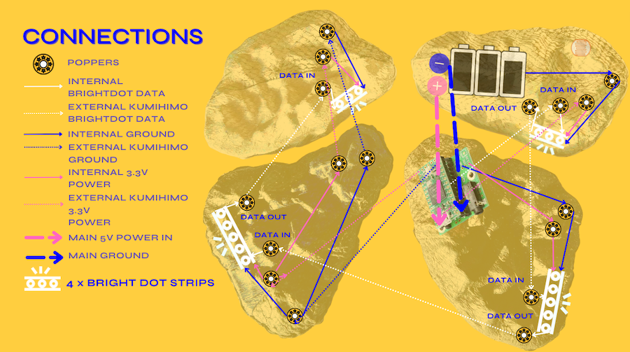
For the final project I had bought a set of Velleman BrightDot Strips. The Medium Brightdot Pack come with 4 pieces. 2 x strips with 5 LEDs and 2x strips with 3 LEDs. My initial design was to use these 4 in the neck piece to show blood flow around the "heart". the more I worked with the chambers the more I realised that they would be much better suited to be integrated into the chamber itself. I was initially going to place them on the external ring put after testing them with the shapes and with some of the prototype leather pieces, I decided to place them inside the chamber where I can make holes in the leather to allow the light to shine through. Again I like the idea of the pieces not looking like they have electronics in them. I made the decision that the larger strips would go into the 2 larger chambers. ALso, in the design I decided to run the lights opposite to the direction of blood flow as I didn´t want to run cables around the neck line.
I tested that they all worked by using a code developed with Chat GPT just to get different values of blue and red. They all went on but they would do some odd things that I didnt code for. Just knowing that they turn on was enough for me to start getting them sewn into the chambers.
#include <Adafruit_NeoPixel.h>

#define PIN 6   // Pin connected to the Neopixels
#define NUMPIXELS 16  // Number of Neopixels can change

Adafruit_NeoPixel pixels = Adafruit_NeoPixel(NUMPIXELS, PIN, NEO_GRB + NEO_KHZ800);

void setup() {
  pixels.begin();
}

void loop() {
  // Cycle through blue spectrum
  for(int b = 0; b <= 255; b++) {
    for(int i=0; i<NUMPIXELS; i++) {
      pixels.setPixelColor(i, pixels.Color(0, 0, b));
    }
    pixels.show();
    delay(10);
  }

  // Cycle through red spectrum
  for(int r = 255; r >= 0; r--) {
    for(int i=0; i<NUMPIXELS; i++) {
      pixels.setPixelColor(i, pixels.Color(r, 0, 0));
    }
    pixels.show();
    delay(10);
  }
}
Debugging
Getting the Velleman Brightdots running properly was a bit of a mission. Trying them on a Teensy, powered by USB from a laptop and using the same power pin, 5V, as the LDR voltage dividers were using, yielded poor and inconsistent results. It was as if the hardware was offsetting the values defined in code. As an example it was impossible to get the first LED on the strip to display red and green. In the video below you can see how the first LED doesn´t light up. Its also supposed to cycle through different colours but they are behaving very erratically.
As before I assumed this was a library issue. It says that these are compatable with the Adafriut Neopixel Library and with the Teensy but several attempts were made to offset the LED numbering scheme with no success. Eventually, I went out and bought a new development board, Velleman’s VMW101 for testing if it was a library issue. This is produced by the same manufacturer as the LEDs, has an internal Bluetooth module and is designed for wearable LED purposes and so this would be an ideal solution for the project anyway.
It was, of course, problematic to get this board running in the Arduino testing environment, due to poor maintenance of the manufacturers manual and driver downloads. I found the documentation of Alumni, Pauline Gamore which helped a bit with the basic set up but it was still. impossible to find out is the pins were analoug or digital. In the end the correct drivers and settings were found, using the board’s chip itself, the ESP-WROOM-32 from the manufacturer Espressifs, documentation. Also, testing each pins values was that only way to really see what was going on.
Using this new setup the LED test programs finally ran correctly. The LDR setup also worked as intended. Unfortunately, there was no suitable Audio library easily available for the VMW101 platform so it could be swapped out for the Teensy. With it being a sewable board it would be way easier to embed but at least I can add it to my collection of unused development boards I´m now collecting for later projects.
Randomly though, the same offset error as before was stumbled upon during the VMW101 testing when I finally figured ot the issue was that the LEDs require a power of no more than 3.3V and a signal limiting resistor (~300Ω on the data-line). Neither of these had been tested on the Teensy setup. Funny I never even thought about checking the voltage out so I´d been trying to run it out 5V the whole time.
After changing the entire Teensy setup to use 3.3V instead of 5V and installing a 300Ω resistor on the data-line to the LED, the offsetting problem was no more. All the basic LED tests run smoothly and individual LEDs could be controlled as intended. Furthermore, this is useful as ensuring a 5V power supply for the Teensy is significantly more challenging than 3.3V.
Peak Detecting
Now the BrightDots are working and can be individually addressed in the code now its about doing something fun with them. The LEDs are now split into groups for each chamber of the piece. Each group is triggered by a peak detector for each heart beat sample. This means that they blink in time with the heart beats as they are heard.