13 Skin Electronics
Research
Smart Skin Speakers
I was super impressed by this project creating tiny speakers and microphones worn on the skin. This technology unfortunately uses nano tech that is beyond my capabilities this week but I will try to make a small speaker using my very thin silver wire I have at a later date. I left it in Blönduós when I came home to Reykjavik for Christmas.
ElectroDermis
This project also reall impressed me was from the Morphing Matter Lab. ElectroDermis has a range of stretchy fully unplugged wearables that can be used for a variety of functions including monitoring the heart.
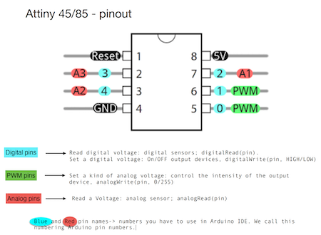
ATTiny 85
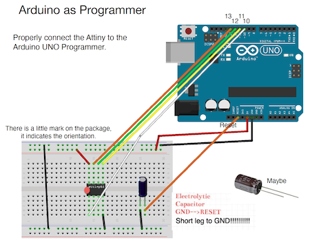
Following the lecture I figured out how to program the ATTiny 85 using the Arduino Uno as a programmer.
To transform the Arduino UNO into a programmer you upload the right code (ArduinoISP) into your Arduino Uno and also upload a library into the board manager. I used this link and pasted it in the Preferences Menu under the Additional Boards Managers URL
- https://raw.githubusercontent.com/damellis/attiny/ide-1.6.x-boards-manager/package_damellis_attiny_index.json
Once this was done and the ATTiny85 pops up in available board then you are ready to program the microcontroller.
Here you can see where to paste the code into the additional boards manager. You can find this in the settings.

Here are the steps we used to Program the ATTiny85
- Connect the Attiny to the Arduino UNO (make sure that the Arduino is uploaded with the ARduinoISP sketch)
- In Arduino IDE: Select board (attiny85 (internal 8MHz)) and port
- In Arduino IDE: Select programmer, Arduino as ISP
- In Arduino IDE: If it is the first time YOU use the ATtiny => Burn the bootloader
- On Breadboard: connect the ATTiny to your input/output devices
- In Arduino IDE: Upload the code to the ATTiny
I then uploaded the Blink Sketch to the ATTiny. It didn´t work with the capacitor initially so I removed it. For some reason once I replaced it after it worked once it worked with the capacitor again. Odd.
In the blink sketch I changed the LED Built in to 1. You upload the sketch using the Upload Using Programmer function in the Sketch menu.
Capacitive Sensor
We learned about capacitive sensors in the second lecture. This works by changing the curve that it takes to get from 0 to 5 volts in this case using resistors. For this class Margret and I used a simple fabric sensor that Louise had made with 4 different conductive copper material shapes connected to 4 different jumper wires. We connected 1 at first using the lowest value resistor we had which was the 47kohm. this worked quite well using the initial code provided from Emma.
As I had 4 different conductive areas to play with I decided to change to code in the sketch to give me different values depending on 4 different resistors
- Pin 2 was still connected to the 47kohm resistor.
- Pin 6 is connected to the 100kohm resistor.
- Pin 8 is connected to the 330kohm resistor.
- Pin 10 is connected to the 1Mohm resistor
I added aditional lines to represent these new imputs. It was a bit tricky to see how I could get all 4 values to show individually on the serial plotter but it turns out I just needed to just put Serial.println once at the end and it worked great for all 4.
#include <CapacitiveSensor.h>
/*
 * Modified example from CapitiveSense Library Demo Sketch (Paul Badger 2008)
 * Uses a high value resistor e.g. 10M between send pin and receive pin
 * Resistor effects sensitivity, experiment with values, 50K - 50M. Larger resistor values yield larger sensor values.
 * Receive pin is the sensor pin - try different amounts of foil/metal on this pin
 */

CapacitiveSensor   cs_4_2 = CapacitiveSensor(4,2);
CapacitiveSensor   cs_4_6 = CapacitiveSensor(4,6);
CapacitiveSensor   cs_4_8 = CapacitiveSensor(4,8);
CapacitiveSensor   cs_4_10 = CapacitiveSensor(4,10);

long total1;  //definition

void setup()
{
   cs_4_2.set_CS_AutocaL_Millis(0xFFFFFFFF);
   cs_4_6.set_CS_AutocaL_Millis(0xFFFFFFFF);
   cs_4_8.set_CS_AutocaL_Millis(0xFFFFFFFF);
   cs_4_10.set_CS_AutocaL_Millis(0xFFFFFFFF);   // turn off autocalibrate
   Serial.begin(9600);  //open communication
}

void loop()
{
    long total1 =  cs_4_2.capacitiveSensor(10);
    long total2 =  cs_4_6.capacitiveSensor(10);
    long total3 =  cs_4_8.capacitiveSensor(10);
    long total4 =  cs_4_10.capacitiveSensor(10);
    Serial.print(total1);
    Serial.print("\t");
    Serial.print(total2);
    Serial.print("\t");
    Serial.print(total3);
    Serial.print("\t");
    Serial.print(total4);
    Serial.println("\t");                 // print sensor output
    delay(100);
}
Piezoresistive Matrix
Next thing was to learn how to use a matrix. For this I designed a fabric matrix for testing. Using a Neoprene top that was in the lab I decided to make an 6x6 fabric matrix. I cut 12 strips of sticky back conductive material and placed 6 on each side of the 2 fabric squares I cut from the top. I also cut out a square piece of foam from an old hoodie with squares cut ot to sit between the 2 layers.
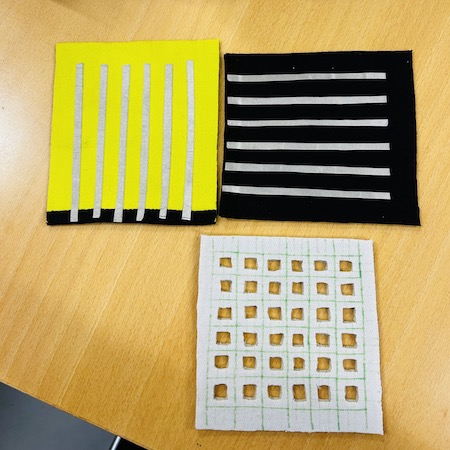
For the matrix to work I placed the layers together so they crossed each other and trapped a square of velostat between them. The matrix works when the 2 conductive fabrics touch each other with the velostat in between. This creates a analoge value in that area. After testing the piece I made I wasn´t getting very strong values with the foam insert so I removed it and sewed around the edges making sure that the strips had little bits hanging out of the side that could be connected with alligator clips. You can find many similar projects on Kobakant
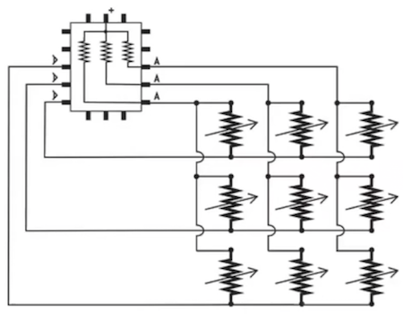
As instructed during the lecture I used this diagram to connect to the arduino. Its very important to make sure the pins are connected correctly to get the right values.
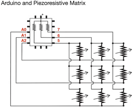
Once the fabric matrix I made was connected as above using the 3x3 connections I uploaded the example code from Emma Pareschi and then checked the values in the serial monitor.
//Emma Pareschi- Dec 2020
//Modify example from Pressure Sensor Matrix Code
//parsing through a pressure sensor matrix grid by switching individual
//rows/columns to be HIGH, LOW or INPUT (high impedance) to detect
//location and pressure.
//>> https://www.kobakant.at/DIY/?p=7443

#define numRows 3
#define numCols 3
#define sensorPoints numRows*numCols

int rows[] = {A0, A1, A2};
int cols[] = {5,6,7};
int incomingValues[sensorPoints] = {};

void setup() {
// set all rows and columns to INPUT (high impedance):
for (int i = 0; i < numRows; i++) {
  pinMode(rows[i], INPUT_PULLUP);
}
for (int i = 0; i < numCols; i++) {
  pinMode(cols[i], INPUT);
}
  Serial.begin(9600);
}

void loop() {

for (int colCount = 0; colCount < numCols; colCount++) {
  pinMode(cols[colCount], OUTPUT); // set as OUTPUT
  digitalWrite(cols[colCount], LOW); // set LOW

  for (int rowCount = 0; rowCount < numRows; rowCount++) {
  incomingValues[colCount * numRows + rowCount] = analogRead(rows[rowCount]); // read INPUT
}// end rowCount

pinMode(cols[colCount], INPUT); // set back to INPUT!

}// end colCount

// Print the incoming values of the grid:
for (int i = 0; i < sensorPoints; i++) {

  Serial.print(incomingValues[i]);
  if (i < (sensorPoints-1)) {
    Serial.print("\t");}
//    Serial.println("");}
  }


Serial.println();
delay(10);
}
Processing
Processing is a flexible software sketchbook that enables you to code for a visual enviroment that can combine the arduino and sensors in realtime. Once downloading Processing for free as its open source. You first upload the matrix code from above, you then can upload a processing sketch. We used the example code below.
/*
Code based on Tom Igoe’s Serial Graphing Sketch
>> http://wiki.processing.org/w/Tom_Igoe_Interview
Reads X analog inputs and visualizes them by drawing a grid
using grayscale shading of each square to represent sensor value.
>> http://howtogetwhatyouwant.at/
*/

import processing.serial.*;

String myString = null;
String inString = null;
int lf = 10;    // Linefeed in ASCII

Serial myPort; // The serial port
int rows = 3;
int cols = 3;
int maxNumberOfSensors = rows*cols;
float[] sensorValue = new float[maxNumberOfSensors]; // global variable for storing mapped sensor values
float[] previousValue = new float[maxNumberOfSensors]; // array of previous values
int rectSize = 0;
int rectY;
void setup () {
size(600, 600); // set up the window to whatever size you want
rectSize = width/rows;

//println(Serial.list()); // List all the available serial ports
String portName = Serial.list()[2]; // set the number of your serial port!
myPort = new Serial(this, portName, 9600);
myPort.clear();
myPort.bufferUntil('\n'); // don’t generate a serialEvent() until you get a newline (\n) byte
background(255); // set inital background
smooth(); // turn on antialiasing
rectMode(CORNER);
}

void draw () {
for (int i = 0; i < maxNumberOfSensors; i++) {
fill(sensorValue[i]);
rect(rectY, rectSize * (i%rows), rectSize, rectSize); //top left
if((i+1) % rows == 0) rectY += rectSize;
}
rectY=0;
}

void serialEvent (Serial myPort) {
inString = myPort.readStringUntil(lf); // get the ASCII string
println("test");
if (inString != null) { // if it’s not empty
inString = trim(inString); // trim off any whitespace
int incomingValues[] = int(split(inString, "\t")); // convert to an array of ints

if (incomingValues.length <= maxNumberOfSensors && incomingValues.length > 0) {
for (int i = 0; i < incomingValues.length; i++) {
// map the incoming values (0 to 1023) to an appropriate gray-scale range (0-255):
sensorValue[i] = map(incomingValues[i], 0, 450, 0, 255); // stretch 5×5
sensorValue[i] = constrain(incomingValues[i], 0, 255); // stretch 5×5
println(sensorValue[i]); // print value to see
}
}
}
}
The next step was connecting the full matrix 6x6. It took alot of crocodile clips which were always in short supply but once I had enough I used the exact same code but with a couple of adjustments. In Arduino I increased the number of rows and columns to 6 each from 3 and then I added the extra pins as you can see from the snippet below.
#define numRows 6
#define numCols 6
#define sensorPoints numRows*numCols

int rows[] = {A0, A1, A2, A3, A4, A5};
int cols[] = {5,6,7,8,9,10};
int incomingValues[sensorPoints] = {};
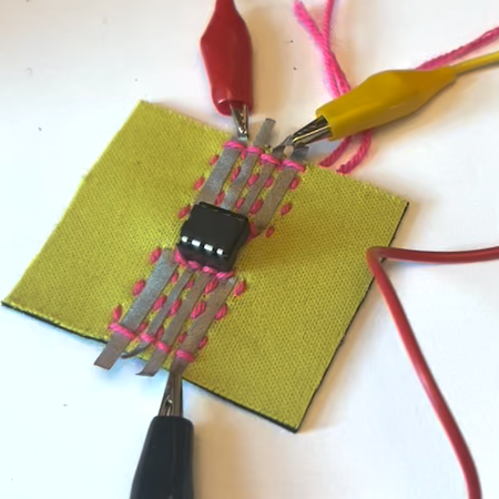
ATTiny Connector
Now I had the ATtiny working I realised just how difficult it is to connect anything to it. I decided to make a little house for it to connect to as the pins were just awkward. I got a little chip basket for it so it could be easily removed (as it dosn´t belong to me) and sewed this onto a piece of fabric with larger connected areas from conductive fabric.
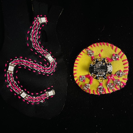
GemmaMO
Even though I didn´t end up using it in the end I also made a little house for the Gemma MO I borrowed from the lab too. I used the same principle except I used little conductive O rings to connect it to the circuit as these can be opened up and the unit removed. My first idea was to make a fabric neopixel circuit with the Gemma MO and 5 Velleman BrightDots as a jewellery piece. I did get this working and it started the prototyping for my final project but I didn´t think it worked for this project brief. I used the same process for setting up the Gemma MO by installing the board in Arduino. One thing to note. I had a hard time uploading the test sketch for the neopixels but I found out that it was jammed and not recieving the upload. Its more important with these smaller development boards to use the reset button which on the Gemma is a small white button. This clears the system and allows it to upload the sketch properly.
I used the Rainbow code from Emma Pareschi to test the Neo Pixels as this proved to be very reliable during wearables.
//Emma Pareschi 2020
//Adaptation of the example Standtest

#include <Adafruit_NeoPixel.h>

#define LED_PIN    A0

// How many NeoPixels are attached to the Arduino?
#define LED_COUNT 5

// Declare our NeoPixel strip object:
Adafruit_NeoPixel strip(LED_COUNT, LED_PIN, NEO_GRB + NEO_KHZ800);

uint32_t off = strip.Color(0, 0, 0);
int num_rainbow = 5;

void setup() {

  strip.begin();           // INITIALIZE NeoPixel strip object (REQUIRED)
  strip.show();            // Turn OFF all pixels ASAP
  strip.setBrightness(50); // Set BRIGHTNESS to about 1/5 (max = 255)
}

void loop() {

  rainbow(10);             // Flowing rainbow cycle along the whole strip
  strip.fill(off, 0, 10);  // turn the strip off
  strip.show();  //display the color
  delay(1000);

}

// Rainbow cycle along whole strip. Pass delay time (in ms) between frames.
void rainbow(int wait) {
  // Hue of first pixel runs 5 complete loops through the color wheel.
  // Color wheel has a range of 65536 but it's OK if we roll over, so
  // just count from 0 to 5*65536. Adding 256 to firstPixelHue each time
  // means we'll make 5*65536/256 = 1280 passes through this outer loop:
  for(long firstPixelHue = 0; firstPixelHue < num_rainbow*65536; firstPixelHue += 256) {
    for(int i=0; i<strip.numPixels(); i++) { // For each pixel in strip...
      // Offset pixel hue by an amount to make one full revolution of the
      // color wheel (range of 65536) along the length of the strip
      // (strip.numPixels() steps):
      int pixelHue = firstPixelHue + (i * 65536L / strip.numPixels());
      // strip.ColorHSV() can take 1 or 3 arguments: a hue (0 to 65535) or
      // optionally add saturation and value (brightness) (each 0 to 255).
      // Here we're using just the single-argument hue variant. The result
      // is passed through strip.gamma32() to provide 'truer' colors
      // before assigning to each pixel:
      strip.setPixelColor(i, strip.gamma32(strip.ColorHSV(pixelHue)));
    }
    strip.show(); // Update strip with new contents
    delay(wait);  // Pause for a moment
  }
}
Silicon Skin Circuits
To actually get these on the skin I decided to do a few experiments with Silicon as I loved working with it in soft robotics. As before, silcon we have is Smooth-On OOMOO fast curing mold making silicone kit. The technique I used was to mix the silicon A in equal parts to silicon B as directed. I carefully poured a very thin layer of silicon on perspex and banged out the bubbles. I left that to dry for 4 hours. I very roughly made a few matrixes, a capacitive touch circuit, a pressure sensor and an LED by laying a combination of conductive materials and velostat on the silicon. I then folded another layer of silicon over the top and sealing the edges with silicon.
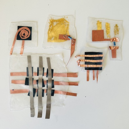
The capacitive touch sensors didnt work. I think the silicon created too much of a barrier between the conductive material and the skin. This sensor doesn’t work like an analog pressure sensor (like velostat) you need to make sure the conductive area is not insulated. But the silicon works as an insulated layer on this one. Good to know anyway.
Also the smaller matrix wasn´t very effective I think as the touch points were too close together with it being a 6x6 matrix. You can see the test below.
Silicon Matrix
The Larger silicon matrix I made did actually did work quite well appart from the the slight connection issue in the top corner. Below you can see me wearing it on my arm and getting values in the serial plotter. Different coloured lines drop to the bottom as the connection is made.
LED
I also embedded an LED into the silicon. The capacitive touch sensor in the same piece didn´t work but I decided to play with the LED instead.
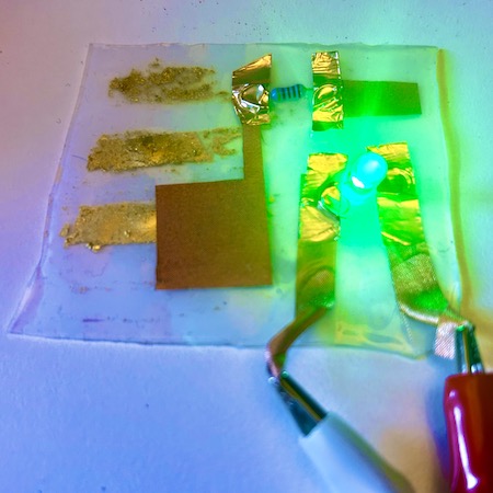
LED with Silicon Pressure Sensor
The pressure sensor was made by trapping a small square of velostat between 2 spirals of conductive copper fabric and then trapping this in the silicon. It works as you can see below.
ATTiny and Silicon LED
Finally I decided to combine the hardware and the silicon together by running the LED from the ATTiny. Using the blink sketch uploaded you can see the 2 working together here.
Conclusion
To be honest I wish I had way more time to explore this particular project but many of the things I made naturally evolved into my final project. You can see more of this in the Lights section of my final project here and the Sound section here
2 Weeks Post Hand In
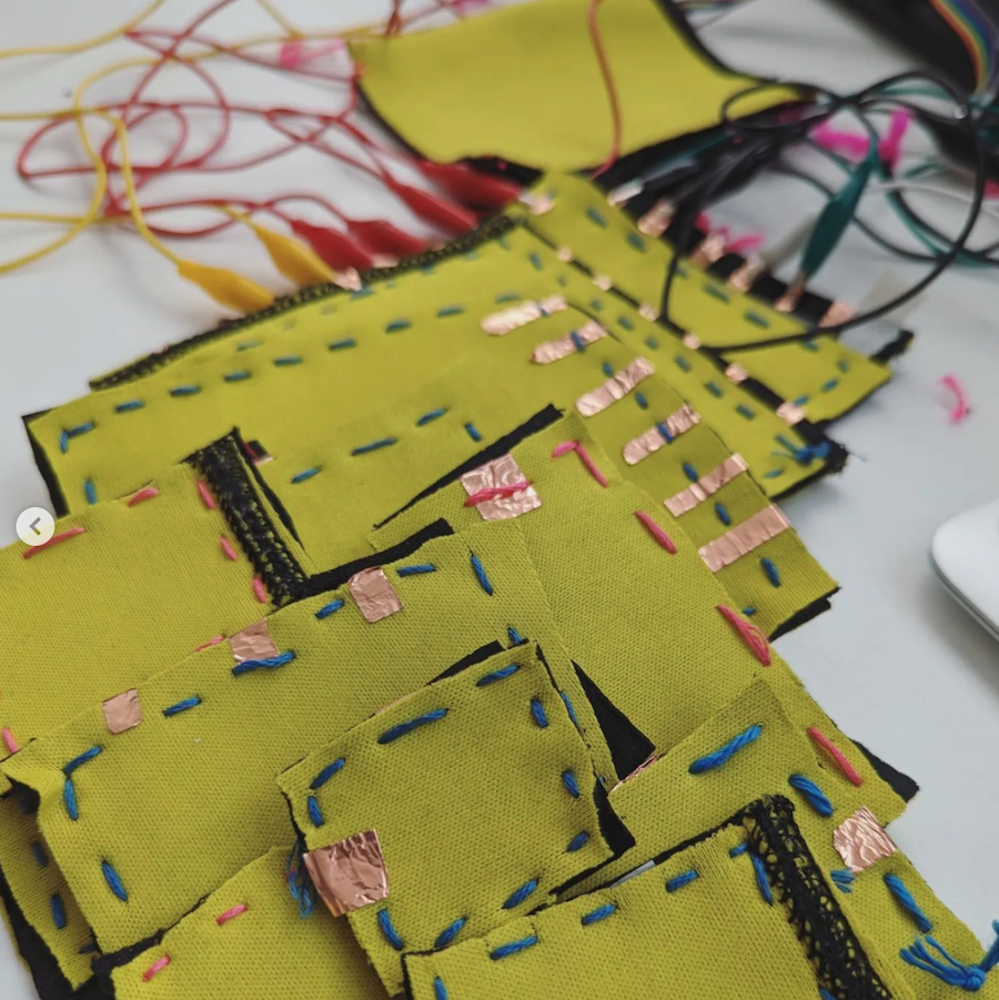
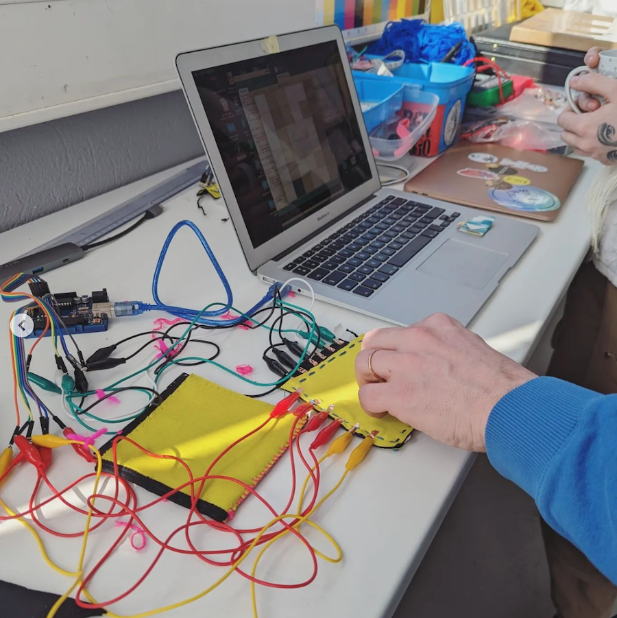
Altough I never fully realised the potential of the matrix I made it was a joy to invite the Intelligent Instruments Lab to Blöndúos to spend the weekend experimenting with conductive textiles and music making. During the weekend I showed the participants my fabric matrix and they made loads of the same design I created here to do experimentation with music making back in Reykjavik.
Tools
Files
Grasshopper Definition for the Cover