Form
The Heart
Planning
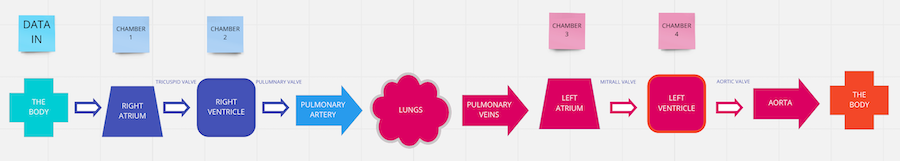
I decided the first thing I needed to get my head round in this project was how the heart actually works. If I can get my head around Cardiac function properly I could understand better how the flow of the piece should go. Firstly I did a quick flow chart to understand how the blood flows through the system.
Anatomy
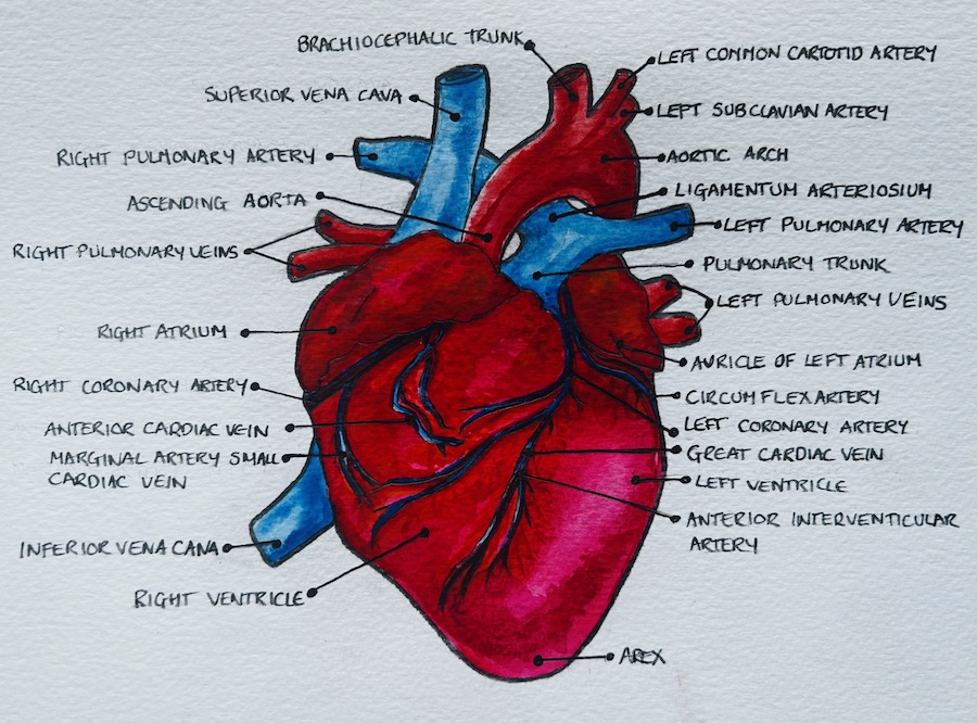
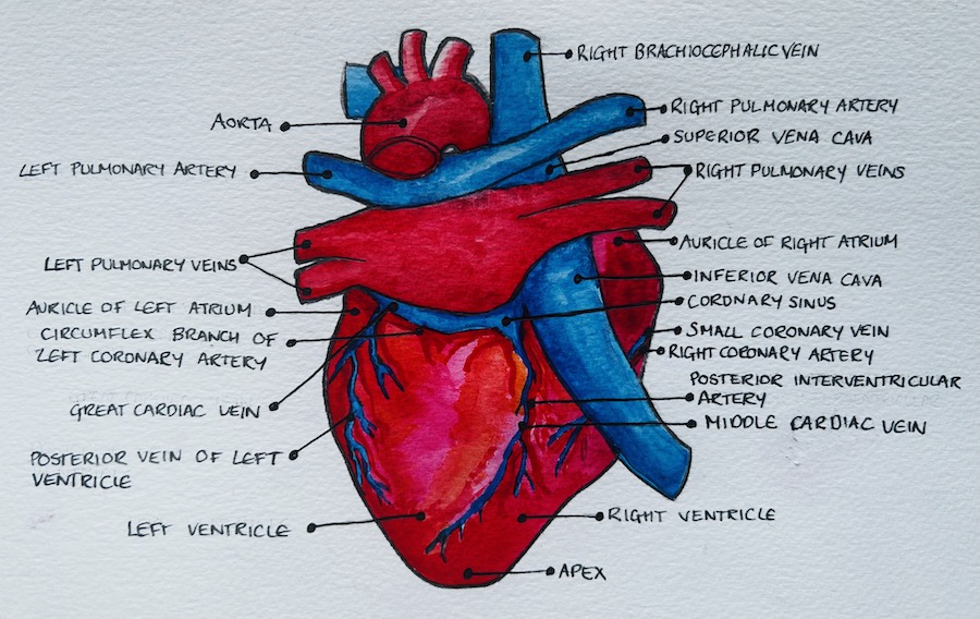
After doing this simple chart I still wasn´t getting my head around it as a 3D concept so I decided to go back to my old anatomy drawing ways from before I was a creative to try to create some nice illustrations. I wanted to do this mainly because I havent painted for ages and I wanted to get out of the computer for a bit too.
Blood Flow
The most important function of the heart is to pump deoxygenated blood to the lungs, collect oxygenated blood back for the lungs and to pump this back round the body in a loop. I decided to look at this system.
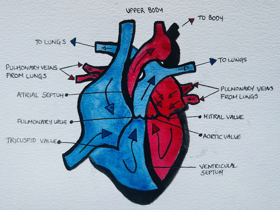
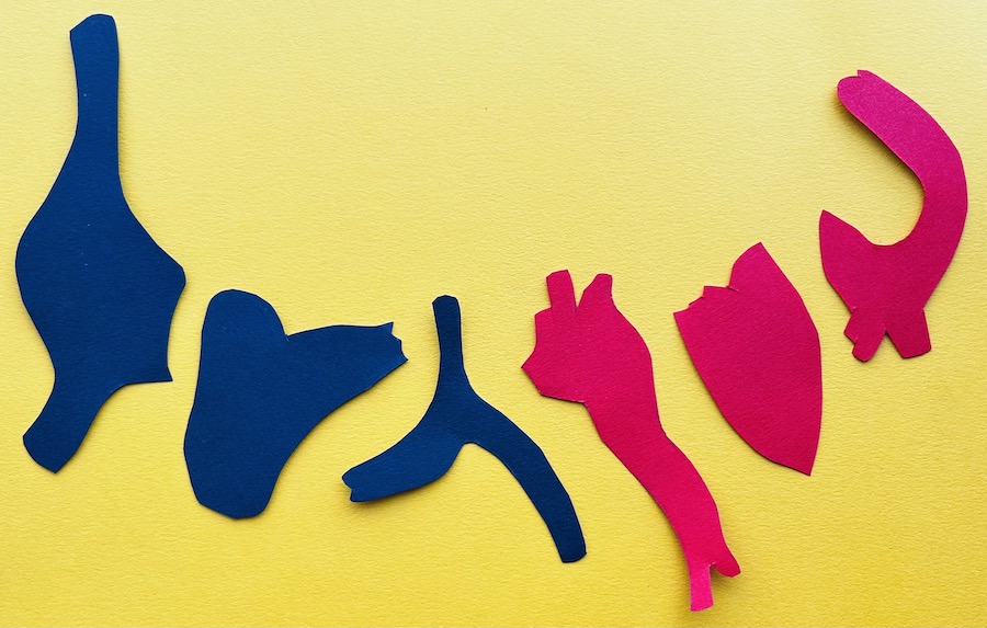
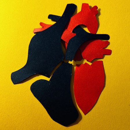
I really like the shapes formed in this diagram so I copied these parts onto coloured card. The blue card is for the parts that deal with deoxygenated blood and red for oxygenated. Here I am starting to pick the heart apart as I am very consious that the project doesnt look like a kids school experiment. Taking apart these forms shows the chambers and major transport parts in the blood flow system. I also want to play with modularity as these parts will be replaceable and as circular as you can make e-textiles.
Grays Anatomy
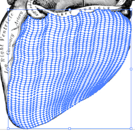
I went back to my early interest in anatomy when I was given a copy of Grays Anatomy. It is still used extensively as a text book on anatomy till this day and I spent hours looking at the illustratrions by Henry Vandyke Carter. For a more detailed shape of the parts of the heart I wanted to use I decided to copy the shapes directly from these illustrations in Illustrator to get boundary surface for use in Rhino.
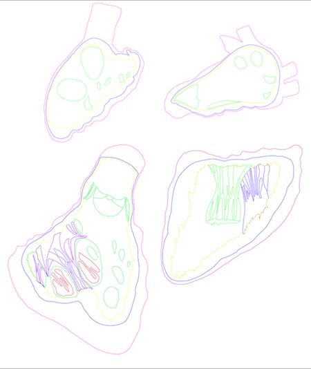
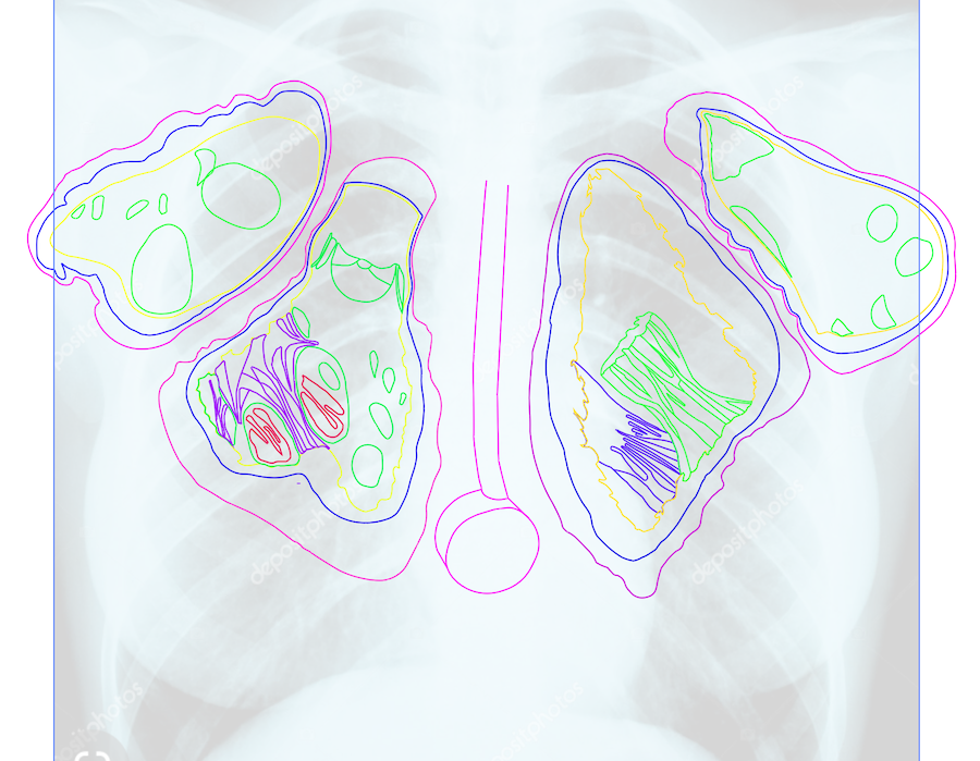
- Below you can see the illustrations I used to create my curves
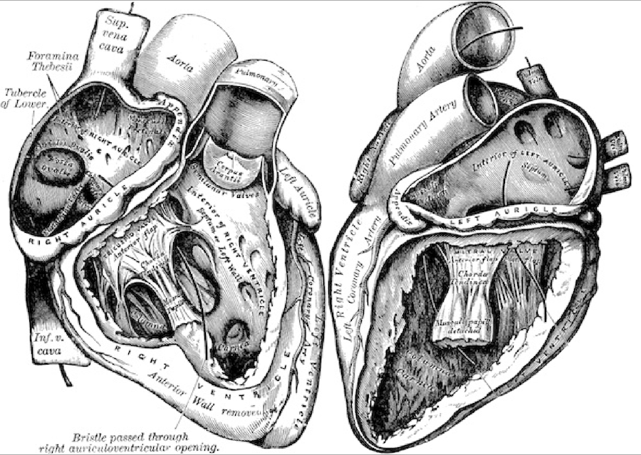
I decided to draw basic lines around the inner wall, outer walls, chambers and then any interesting structures inside. I also simplified the shapes a little to make them a little more curvy.
- Below you can see the four chambers of the heart in drew in Illustrator with different colours assigned to the curves to make it easier to separate.
Composition
Now I have these shapes I decided to play around with the final form in 2D in Illustrator. I made the decision that even though this is anatomy pieces I want it to be slightly off kilter so I am not just making a high school project. Therefore I am not married to the position or size of the component pieces. After playing around I have removed the obvious artery shapes from the left and right atrium sections as my plan is to use these parts in data and power connections outwith the basic fish leather pieces that will connect the electronics and provide the structure of the nect piece. After some messing around I think that the piece will look a bit like this.
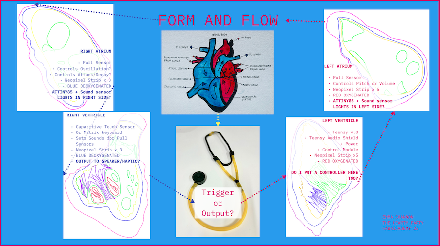
After starting to program the sound prototype using the Teensy I am starting to get a feel for how the piece is actually gonna work. This definately will change as the shapes evolve but my intial design is looking a bit like the picture below. There are still many quections that cant really be answered
Chamber Design
Now to get on with actually making the shapes all the electronics are going to be imbedded in. I was hoping to get my actual heart data to form the 3D moulds using Grasshopper but once I received the CDs from my Cardiologist (thank you too the wonderful Þórbjörn) I realised that the echocardiogram data with the sound waves from my heart didn´t open. I only have a recording of it from my appointment showing the 6 different sounds and waves you get using ultrasound. I then even looked at the posibility of making my own open source ultrasound machine which other people are working on. Here you can see one of these projects Echopen.
- Below you can see my echocardiogram from my 6 month check up and see the potential for using this information which I would certainly like to revisit at a later date.
Grasshopper Research
Weaverbird
My intial idea was inspired by a fellow current participants project from digital bodies. Shahd Farran did a wonderful project where she linked sound into grasshopper using to create forms.
My first exploration was is trying to copy this definition to use with my shapes. It actually proved to be more complicated than you would of thought as the definition used the Firefly plug in that only works on PC which of course nobody uses in the Textile Lab so we set it up on the computer that runs the laser cutter. Luckily Margret was also using pretty much the same set up for her project except with video. I was planning on getting it all running with the Firefly Plugin. This software would allow me to plug into an arduino or teensy directly with real time data from Grasshopper.
The set up here wasn´t very good at responding to sound and without the ability to plug in an audio file and the PC being over 10 years old, unfortunately, the firefly route I was looking at to create form just wasn´t working for me for this project. I´m sure as soon as the firefly plugins are available in mac I would love to play with them more.
Delaunay Mesh
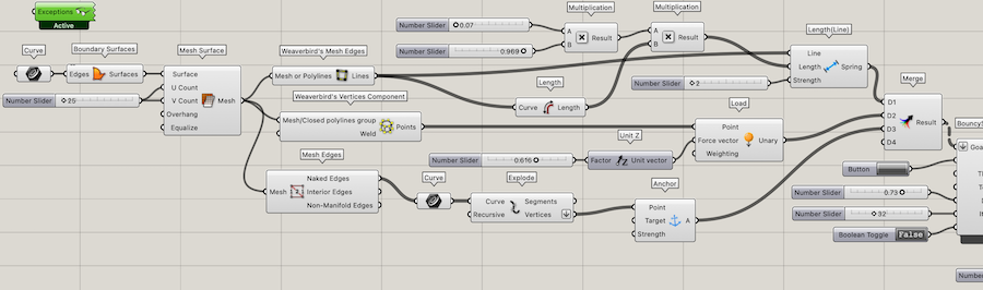
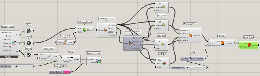
Next I just removed the sound aspect from the definition but I was still left with the rounded cap shape you can see in the GIF above. I was trying to work out a system where I could take my curves shapes from above and make each one of the inner curves of the shape have an different level of attraction to the cap shape I was working with. We were playing with different ways of making a mesh from it when we plugged in the Delaunay Mesh and just with one curve linked in we got a super cool looking shape.
I really liked this form so Next it was a mission to figure out how to make it a usable surface. Louise and I tried various different ways like dropping a surface on top in grasshopper while I played in rhino trying to make it a surface. This made Louise go away and really look at it (she does love a challenge) and as you can see below the secret was to use points, turn then into faces and then into the mesh needed.
Using this definition on the shape I had for the left venticle I decided to go ahead and test out the shape as a print. I also wanted to test my shiny new filament so badly.
- Below is the 3D model I made for this prototype that can be downloaded.
Printer Settings
Fillament Type - Generic PLA
Size - Normal 0.3mm
Layer Height -0.2mm
Top/Bottom Thickness - 0.8
Top/Bottom Layers - 3
Infill - 10%
Infill Pattern - Grid
Printing Temperature - 220°C
Build Plate Temperature - 60°
Print Speed 60mm/s
Build Plate Adesion - skirt
Fish Leather Test
It printed well and I was happy with the result. I was just very concerned that the details would get lost in the fish leather. Unfortunately I was right. I tested it out using a similar process that I had done in my textile scaffold week project but may be slightly more organised. Firstly I cut red and yellow salmon skin into long thin strips length ways up the fish skin. I then chopped these into roughly equal parts that fit across the form. I then go on with making the glue. Last time I wasnt very scientific at all and basically stirred 2 parts flour into one part water till I got a gloopy substance. This time, after reserching a bit about the types of glue that work with just regular leathers, I followed some general instructions from a youtube tutorial from DAS Bookbinding but the steps I personally used are below.
Flour Glue Instructions
Take 2 saucepans with one than fits into the other one for a bain marie.
Place 250ml of cold water in the bottom saucepan.
Place 250ml of cold water in the 2nd saucepan and place this on top of the second one.
Add roughly 1 heaped tablespoon of flour into the water in the top saucepan.
Add 2 drops of clove oil to prevent molding, (I only had CBD oil so this is one chilled out mixture.).
Place both saucepans on a moderate heat.
Whisk the flour and water mixture as the water heats.
Once the water in the bottom saucepan is boiling continue to whisk together for 20 minutes.
Take off heat and allow to cool a little before use.
Should be the consistancy of light wallpaper paste.
My technique for this piece was get a strip of fish leather and place it in the glue. I then run the glue mixture into the piece until its well coated. I then place it on the mould where i would like it to be and I massage the leather into the form making sure to push it into the nooks of the shape. I did use a hook to push it into difficult places. one i have that massaged in I took another piece at a right angle to the first and repeat the procedure. When it comes to the 3rd piece I lay it half over the 1st piece and start building up the texture at right angles untill the shape id covered. I found that it works well to sometimes work back into the leather with extra glue with your fingers to keep massaging the leather together and to keep it in place.
The final result as I said was disappointing. The fish leather is too textured to pick up the nice fine details I had made the the delauney mesh. I also placed the material I tested in a weird way so it kinda looked like a lump of beef. Nothing ventured nothing gained as they say so at least I know.
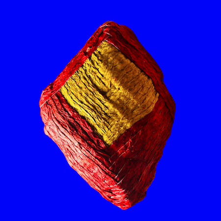
Image Sampler
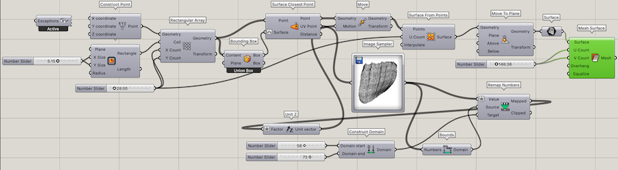
After all the disappointment of these grasshopper definitions I decided to try out another way of acheiving the forms and I went back to the trusty Image Sampler I had used to create my 3D printed fabric in Computational Couture Week and also my CNC mould in Textile Scaffold Week. Of course it wasnt so trusty at all when I first started working with it again. In true Grasshopper style the same definition used in the exact same way gave wildly different results. Then I realised that it only worked using screenshots of the image I wanted. I was so happy I sent Louise this video of it kinda having a form using the extended definition that you can find here - CNCFinal
I put the shape of the left atrium I had made into Illustrator and started playing around with the gradients of black and white as thats how the image sampler works, by mapping the blackest as the highest point and white as the lowest.
- Below you can see the first round of attempts at getting a decent gradient through the medium of screenshots
The shape that I ended up with looked alright so I went ahead and test printed it.
Printer Settings
Fillament Type - Generic PLA
Size - Normal 0.3mm
Layer Height -0.2mm
Top/Bottom Thickness - 0.8
Top/Bottom Layers - 3
Infill - 10%
Infill Pattern - Grid
Printing Temperature - 220°C
Build Plate Temperature - 60°
Print Speed 60mm/s
Build Plate Adesion - skirt
Fish Leather Test
At first I was happy with the shape but when I went to the fish leather I realised that it was just too plain. The Gradients were just not defined enough so the fish leather just looked like a slightly raised bowl as you can see below.
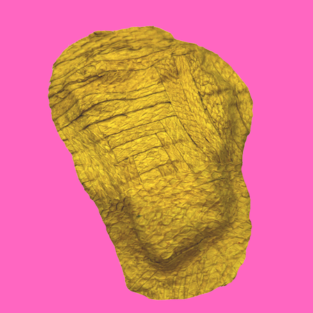
Image Sampler Part 2
Next I tried many more incarnations of gradients to see if I could find the magic combination that would give me the happy medium I was searching for.
At this point I was just uploading images of random shapes just for fun. I placed in some of the stent patterns I was working on at the same time and noticed that there was alot more contrasts or lumpy bits as I call then that I think work so much better when moulded. I decided to draw some new shapes to work from using the pictures from Greys Anatomy again. As I´m a complete novice and I don´t know what I´m doing I made the biggest kinda happy accident ever. I drew a path around the space of the left ventricle and I was looking for a completely different tool when I spotted a tool called "create gradient mesh" and as I work in Rhino all the time I pressed it and it gave me a super nice shape somehow.
As this was only a path I pressed a bunch of buttons and somehow this turned into a stroke. (More about this later but moral of the story, write down how you do stuff when you do it.) I put the screenshot of this mesh into the image sampler and it magically gave me the shapes I´ve kinda been looking for and I have no logical reason why but it is.
Extruding and Mesh Trim
I decided, after the last prototype, that I needed a border around the bottom of the geometry. I decided on roughly a centimeter to be added to the base. After playing around in grasshopper I felt it was just easier to do it in Rhino. These are the steps to get the final form.
- Bake the shape in Grasshopper.
- Change to front view.
- Extrude shape below the cplane making sure the curved top edge is below the length you want to add as below.
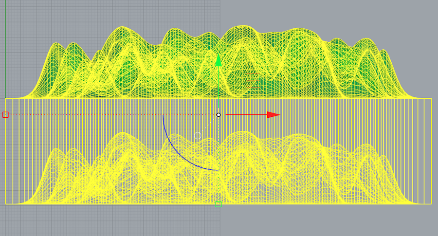
- Draw a straight line across the shape at the length you want to extrude to as in the image below.
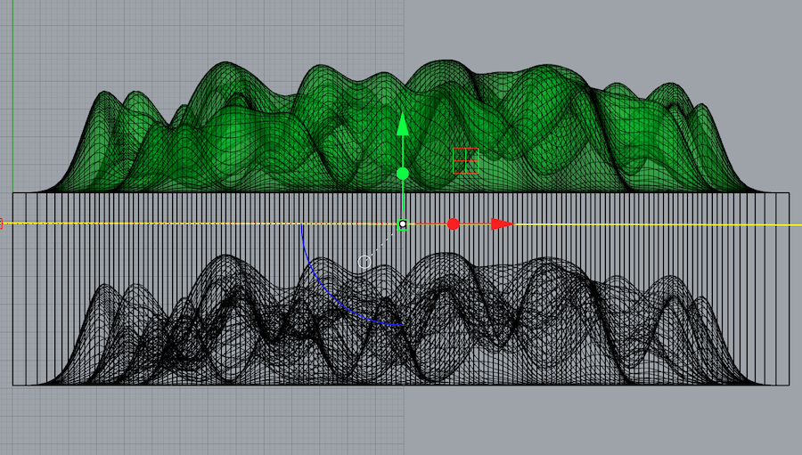
- With the line highlighted (the cutting object) type the command MeshTrim.
- Select the mesh below the line to remove it. You should be left with the shape below.
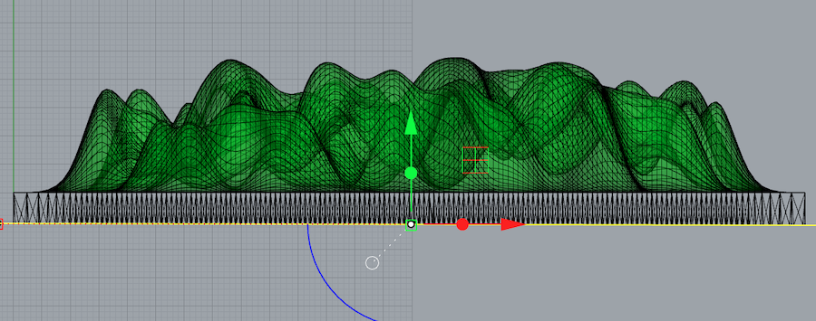
- Be careful to press escape after the bottom is trimmed or it will keep cutting parts you don´t want to lose.
- Move the model to the C plane.
- Use the Cap command to close the geometry.
- Save this as an STL to transfer to the Ultimaker Cura Software for the 3D printing gcode.
Printer Settings
Fillament Type - Generic PLA
Size - Normal 0.3mm
Layer Height -0.2mm
Top/Bottom Thickness - 0.8
Top/Bottom Layers - 3
Infill - 10%
Infill Pattern - Grid
Printing Temperature - 220°C
Build Plate Temperature - 60°
Print Speed 60mm/s
Build Plate Adesion - skirt
Fish Leather Test
This time I decided to do 2 tests with the rest of my burgandy fish leather on this new form. I had actually sewn the bottom halves of the leather together with an overlocker during Textile Scaffold week that I hadn´t used therefore creating a larger piece. I cut the two loose bits of the leather off and cut these into strips to be woven as I had done before. I created the flour glue in exactly the same way as the test before too as it also worked out very well.
Flour Glue Instructions
Take 2 saucepans with one than fits into the other one for a bain marie.
Place 250ml of cold water in the bottom saucepan.
Place 250ml of cold water in the 2nd saucepan and place this on top of the second one.
Add roughly 1 heaped tablespoon of flour into the water in the top saucepan.
Add 2 drops of clove oil to prevent molding, (I only had CBD oil so this is one chilled out mixture.).
Place both saucepans on a moderate heat.
Whisk the flour and water mixture as the water heats.
Once the water in the bottom saucepan is boiling continue to whisk together for 20 minutes.
Take off heat and allow to cool a little before use.
Should be the consistancy of light wallpaper paste.
So first I wove the strips on using the exact same technique as all the previous tests. This was a lot more of a challenge as the undulation of the model was way more than the previous ones. I left it to dry on top of the radiator for 2 hours then peeled it off the form.
The Circulatory System
The arteries and Veins are an important part of the cardiac system. My type of heart attack is called a Inferior Myocardial Infarction or basically a blockage of the lower artery of the right ventricle. During the surgery, 2 stents were implanted into my artery using a guide wire that is placed in the artery in my right wrist. The stents were implated with the use of inflatables which open the stent in the artery to open the blockage to allow blood flow again. If you would like to see the actual proceedure taking place then please look at the video below that shows my operation as it happened. You can see the blood flow restored again by the end. My lovely Cardiologist gave me the files so I can watch it again (I was awake during this procedure.) I have increased the speed of the video to 300% as it was good practice using Premiere Pro, another new software, for later use in the project.
Arteries
I want to create connections between the "chamber" sections of the heart in the style of arteries and veins. I would like these connections to transfer power and data between the embedded wearable electronics. When I have been working in electronics in my previous projects I have tried to make the projects as soft as possible and this I wanted to continue in this project. Making handamde components and connections where possible. The piece also has to be modular and fixable to make it as sustainable as it can be for a project using components and 3D printing. I tried using a kniting cord maker to make tubes and then Louise suggested Kumihimo Braiding When I was much younger I loved making freindship bracelets so I was immediately drawn to the technique. To test it out (and to try out my new shiny 3D printing filament), I downloaded some 3D models from Thingiverse here and decided on the small size to start with and then printed it.
Printer Settings
Fillament Type - Generic PLA
Size - Normal 0.3mm
Layer Height -0.2mm
Top/Bottom Thickness - 0.8
Top/Bottom Layers - 3
Infill - 40%
Infill Pattern - Grid
Printing Temperature - 220°C
Build Plate Temperature - 60°
Print Speed 60mm/s
Build Plate Adesion - Skirt
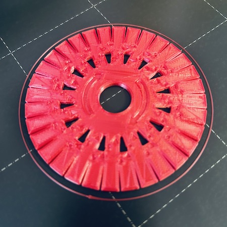
Now I had to learn how to use it. I followed the simple tutorial that came with the print showing how to do the basic 4 thread braid.
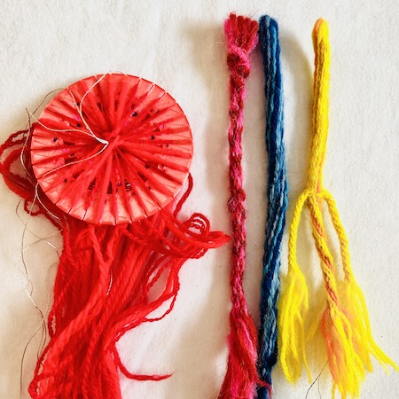
Once I had accomplished this 4 thread braid. I did another one but this time trapping a conductive thread in side the braid as I went. My technique for this was to move it out of the way of the "active" threads as I was working around the wheel. I then did tests with different patterns and sizes. Using all 32 holes you can acheive a thick solid tube that can be split into branches. I like the idea of this technique as again it looks very like the arteries. and its a way of adding interest to the piece and also carrying the power to different chambers potentially using one line,
Arterial Stents
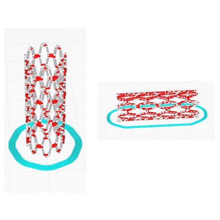
My other area of research was arterial stents of which I have two inside me still. During the Fabricademy process I have been looking at these structures throughout the process for inspiration. After researching the emerging field of 3D printed stents I figured it would be fun to attempt to print them myself. The problem with this approach is how to print these very small structures in a stable 3D form. Obviously the structures I am trying to print is way bigger than the ones that are printed for inside the artery but it is still difficult to get a good clean print. I downloaded one from Sketchfab, just to try out both upright tube models and also how the model would behave on its side. I think you can see the errors that occured in the slicing below. I also attempted to add supports and I didn´t think that was much help.
Pattern
To get the flat 3D models I had to get just a picture of stent structures from one to the many scientific articles on stents available on a google image search.
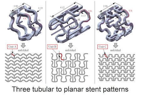
Taking these patterns into Illustrator I did the same technique of drawing the shapes and making it a vector diagram as shown below.
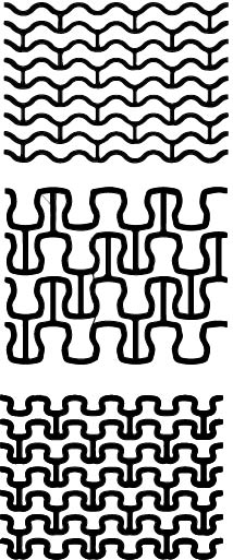
Then I uploaded this diagram into Rhino where I realised how much I had forgotten during my exploration into Grasshopper. Firstly, Its sooooooo dificult to get a surface from these type of curves with holes inside. I´ve been here before. Almost makes me want to never work with "holey" objects ever again. Finally I figured out that you can draw a plane surface underneath the curves and carefully trim the surface away from the holes in order to get the surface. This took a fair amount of time but once I had these surfaces it was very simple to extrude the pattern by 3 to create the 3D flat pattern I wanted. Below you can see and download my 3D Model.
Next up I but it into Ulitmaker Cura and sliced it for the print. I changed the scale so it was 50mm wide as that seemed like a good test size. I changed the fillament to the shiny blue and used the settings below -
Printer Settings
Fillament Type - Generic PLA
Size - Normal 0.3mm
Layer Height -0.2mm
Top/Bottom Thickness - 0.8
Top/Bottom Layers - 3
Infill - 100%
Infill Pattern - Grid
Printing Temperature - 220°C
Build Plate Temperature - 60°
Print Speed 60mm/s
Build Plate Adesion - Skirt
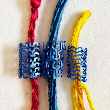
As my plan was to see if they formed into a tubular structure as soon as the print was finished and they were still warm I took them straight off the bed and gently rolled them around a pen. To my delight they bent round quite nicely forming a very nice curve witout really being heated properly. One piece did break a bit but overall I think it worked quite well. I think these would make very nice jewellery parts in general so worth further exploration in making better shapes, with more rounded edges. I need to prototype different sizes and also figure out a good way of shaping them and sealing them. I also like the idea of using them to cover the ateries again bringing the inside out theme into the design.
- Below you can see my prototype Kumihimo braids with the prototype stent designs.