12 Soft Robotics
Research
Angioplasty
So its soft robotics week so its quite personal to me as inflatables were literally used to save my life. When I had a heart attack I had a 2 stents put into my artery using an inflatable to place the stents in the correct place. this procedure is called angioplasty.
- Below you can see a video explaining the angioplasty procedure.
I found some other interesting projects in biomedical research surrounding the heart.
Inflatable Stents
The Dalio Institute of Cardiovascular Imaging have been developing inflatable stents for a wide range of endovascular treatments removing the need for the metal or plastic additional stents.
- Below you can see a video explaing how they have been inspired by soft robotics and how they have been using similar tools to create the inflatable stent.
Soft Robotic Heart Pump
Scientists atHarvard have developed soft robotic technology using biomimetic materials for use internally to restore the ability of the heart to pump blood although only in Yorkshire pigs so far. Most soft robotics have been used in external applications before for mobilty with grippers or aids with walking so this and the potential of inflatable stents are promising developments. The device combines concentric rings with helical structures to mimic the orientation of the outer two layers of cardiac muscle in mammalian hearts.
- Below you can see the action of the robotic which is placed over the heart like a sleeve. Its also fully customisable.
Heart In Your Hands
Heart In Your Hands allows the interaction with a robotic heart that beats in time with your own or someone elses heart that can be held in the hand. This was designed to also advance the understanding of the heart and health health.
- Below you can see the assembly of the soft robot again using alot of the same techniques we will be using.
Conductive Silicon
This amazing post from DigitalNaturalism on Istructables has loads of ideas with using carbon fiber laced silicon in a variety of projects. As soon as I am back anywhere near a store I would like to try out some of these techniques.
Silcon Moulding Part 1
3D Printing Part 1
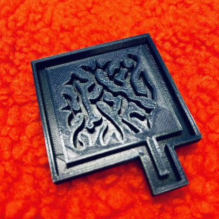
First I decided that I wanted to play around with making moulds with some of the motiffs I had used in previous projects from the heart cell cymatics as a smaller mould to be used with silicon. These had to be looked at in a slightly different way for this purpose whereas before i used image sampler in Grasshopper that had given nice rounded forms, for this I needed I nice straight edge around the shapes to extrude. Here I used the same technique as I had used to recreate my curve for the knitting machine cover in Open Source Hardware. I put the screenshot that i had adapted to put into the image sampler into illustrator and drew around the shape to get the vectorised form.

I drew a box with a additional rectangular addition on it for the airway and exported selected into Rhino. Firstly I actually made the oposite form to what I needed as I got confused by what should inflate and what shouldn´t so instead of making the shape as i had in previous weeks I had to think of it as going in instead of out. Basicially this was acheived by creating a series of extrusions of the curves subtracting the curves I wanted to be "stuck". Because this particular image has 5 curves that needed to be removed I had to do 5 separate definitions in Rhino to achieve this. The outer wall was made larger to contain the silicon. I also extruded the outside curve as a surface down by 1 to create a base shape for the mould. I moved this manually to the zero point when I baked the curves.
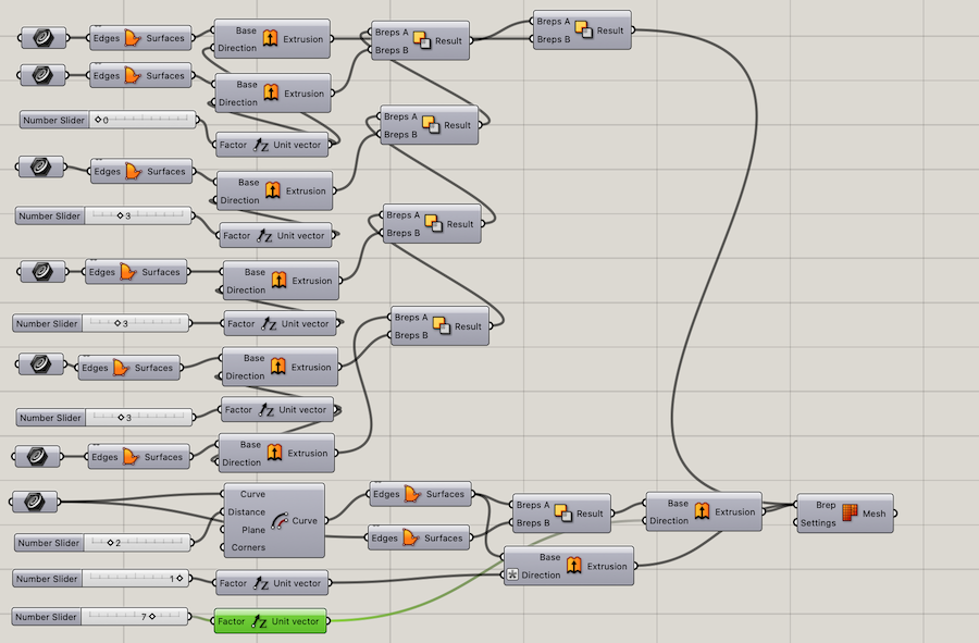 The Grasshopper Definition.
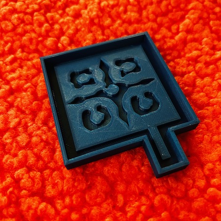
The 3D printing went very smoothly. In the settings I was sure to increase the infill density of the solids to ensure a good quality mould. I placed the model into Cura and the slices looked great with a print time of 2hrs 11mins. I prepared the printer by cleaning the plate with alcohol and I did not need to change the fillament so I was good to proceed. You can find my settings below.
Printer Settings
Fillament Type - Generic PLA
Size - Normal 0.3mm
Top/Bottom Thickness - 0.8
Top/Bottom Layers - 3
Infill - 40%
Infill Pattern - Grid
Printing Temperature - 220%
Build Plate Temperature - 60°
Print Speed 60mm/s
Build Plate Adesion - Skirt
Casting Part 1
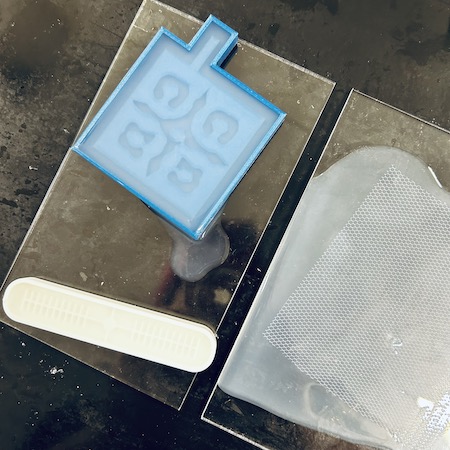
Next step was to cast the mould with the silicon. The silcon we have is Smooth-On OOMOO fast curing mold making silicone kit. The technique I used was to mix the silicon A in equal parts to silicon B as directed. I prepared the mould by washing it and also figuring how much water it held. I decided to make around 50ml of the mixture. I also prepared a piece of netting that was bigger than the mould on a piece of perspex for the closing of the mould. Using a metal stirring rod I carefully poured the 2 parts of the silicon into a beaker and slowly mixed the 2 together being sure not to create bubbles in the mixture. After mixing I very carefully poured the mixture over the fabric first making sure to keep the bubbles to an absolute minimum until the entire piece was covered. I then very carfully did the same into my mould. I had some left over after both were poured so I had enough to make a second fabric piece and gripper mould that was available in the lab. I also made an experiment with the last of it where I poured a small amount into a skyr yogurt list then I placed an e shaped piece of baking paper into this closing it over with the last of the mixture. When all of this was poured I taped then all to raise any bubbles to the surface. I used a dental scraping tool to pop any bubbles i could see. This had a drying time of 4 hours so I placed them to the side to dry.
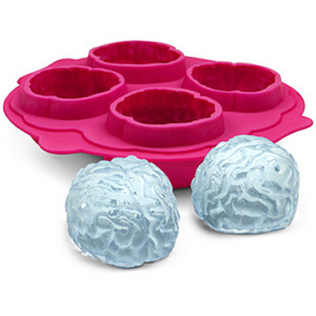
At this point I stared to think about how to incorporate electronics into this technique cause wearables are cool. I quickly got an airpump working (more about this later), so I thought can I embed electronics into the inflatable? I thought about making a mould with a large enough gap in it so it could contain an LED or a pressure sensor. I was about to start working on a new mould in grasshopper when I remembered i had a silcon icecube tray I had bought in a charity shop in Reykjavik that was in the shape of mini brains. These brain shapes were quite deep so if I could find a way of casting a "hole" in these there would be enough space to place the electronics inside these before closing them up. What would be cooler than a light up inflatable brain?
Casting Part 2
I decided to cast the brains at the same time as closing my moulds from my first pour. So this casting started with some reveals. Firstly I carefully peeled off the test I had done with the baking paper. I very carefully teased the paper away from the silicon using a double pointed needle.
I realised that I could probably remove the baking paper from the silicon so I carefully tried to pry this out with tweezers. It was successful but I also poked a hole in it as I was going so in this second casting I decided to try and patch this hole with silicon and also do another one the same but with a circular shape so it would be easier to remove.
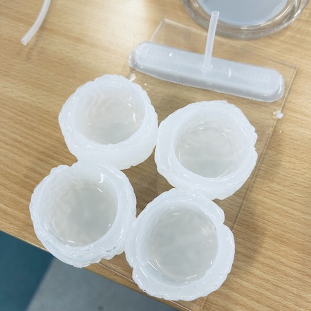
To close my first casts I removed the pours from the 2 moulds and both looked beautiful. No air bubbles at all. The flat ones I had poured as closing moulds were also very nice and super transparent from being poured directly onto the perspex
Now it was time to mix the silicon mixture. I did this exactly in the same way as I had before as this worked very well except I increased the amount to 140ml as I would need a fair amound extra to cast the brains aswell.
The technique I used to close these moulds was to put a very thin layer of silcon on the flat closing pours using a wallpaper scraper to make sure it was flat then I used my finger to place some on the areas I wanted to stick to the closing mould. With the main mould I also cut a small hole at the end of the chanel I had designed to stick out and placed a tube in this gap to make it easier to inflate. I then stuck these parts down making sure there was good contact between the pieces. Finally using a syringe I added extra silicon around the edges to make sure it was all sealed up nicely.
Next up the brains. Now in hindsight, my casting technique here was not the smartest. I thought that just putting some medicine beakers in the mixture to create the gap would be cleaver instead of putting in the extra work to make something that could sit comfortably inside without moving. There was 4 brains and I spent ages readjusting these beakers making sure they stayed in place as they dried. I added water to the beakers to try to weigh them down and ended up spilling water in one of the moulds. It was all kinds of hot mess, I and everything around me was covered in silicon so I didn´t have high hopes for this working out at all. Oh well we will see after it was left to dy over night.
Casting Part 3
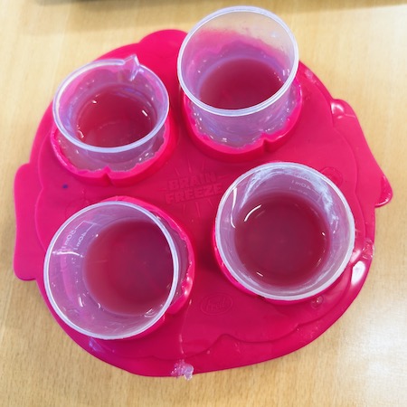
So here we are again with the brain reveal which of course has ended up as a 3rd casting. They have actually turned out better than expected. The one that I spilled water in is still a little sticky on the outside but way more set than I thought. The problem with all of them really is some very small holes in the bottom where the beaker had touched the inside.
I decided to try and patch these up with more silicon. The area inside is large enough to handle a bit of loss with still having plenty space to hopefully embed the electronics. I also realised that my baking paper experiment wasn´t thick enough to handle the removal of the paper so basically I did a remedial casting. I mixed the silicon as before and poured a small amount into each brain swirling it around the edges as I did it. I pored more into the Skyr lid and carfully placed the baking paper mould on top trying to not trap any air between the layers and then I poured more mixture over the top. A also realised I needed to embed a tube for inflation into the gripper. I carefully cut a small hole in the top of it and placed a small plastic tube in the hole and sealed this with the silicon. I then left this over night.
Electronics
RGB LED
I was thinking about what to embed into my brains when they dry so I spent an evening playing with some electronics. I knew that I definately wanted an RGB LED in one of them and as I had only programmed neo pixels and not RGB LEDS before I decided to try to get that working. As this needs to be embeded into a small space in an inflatable brain, I used the KY009 3 Color SMD RGB LED Sensor Module I found in my box of random sensors for testing. This module consists of a full-color LED in red, blue and green with a ground pin. The module has built in limiting resistors to prevent burnout this also means I can have the full unit inside without having external resistors. The circuit itself is very simple.
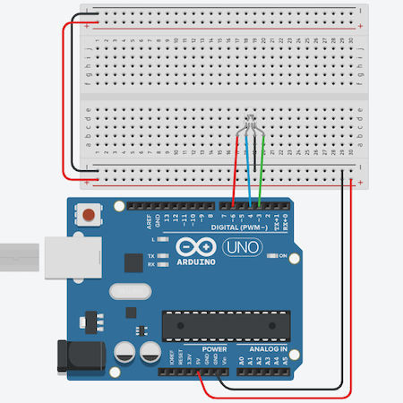
Next the code. I based my code on this great tutorial from Aqib on Arduino Project hub.
The Code
int redLED = 3;
int grnLED = 5;
int bluLED = 6;
void setup() {
  pinMode(redLED, OUTPUT);
  pinMode(grnLED, OUTPUT);
  pinMode(bluLED, OUTPUT);
}
void loop() {
  RGB_color(255, 0, 0); // Red
  delay(1000);
  RGB_color(0, 255, 0); // Green
  delay(1000);
  RGB_color(0, 0, 255); // Blue
  delay(1000);
  RGB_color(255, 255, 125); // Raspberry
  delay(1000);
  RGB_color(0, 255, 255); // Cyan
  delay(1000);
  RGB_color(255, 0, 255); // Magenta
  delay(1000);
  RGB_color(255, 255, 0); // Yellow
  delay(1000);
  RGB_color(255, 255, 255); // White
  delay(1000);
}
void RGB_color(int redLEDvalue, int grnLEDvalue, int bluLEDvalue)
 {
  analogWrite(redLED, redLEDvalue);
  analogWrite(grnLED, grnLEDvalue);
  analogWrite(bluLED, bluLEDvalue);
}
Presure Sensor
So now this code works I wondered how can I make this way more complicated. So I thought it would be cool if I could embed an pressure sensor inside so as the pressure inside the inflatable increased the LED would change colour. It probably won´t work but I decided to have a go. First, I needed a pressure sensor so I found tiny spraps of velostat, neoprene and conductive fabric. I roughly mapped out a size that would fit inside my brains for the prototype.
I stuck the adhesive conductive fabric to the neoprene and sewed conductive thread connections on each side. I then sandwiched the velostat between the layers and sewed around the edges to seal it. I connected it and tested it with a normal LED and it worked.
Sensor Design
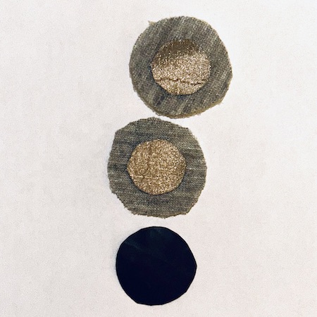
After doing this test sensor I realised that there were some design flaws in its construction. Firstly the conductive threads were on top of the fabric so although it worked, it wasn´t very pleasant to press. There was a connecting wire on top of the design so I figured if these are gonna be inside inflatables then they had to be pretty sturdy and not sharp so to make a hole. I decided to make 2 more sensor components and combine them with 3 different LEDs.
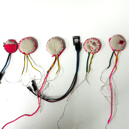
The first new sensor I sewed it so the wires came from the same side I also added 2 extra half moon shaped neoprene fabric bits just to make sure the connections stayed appart. This worked very well when tested so with the 3rd and final one I created a doughnut shaped insert and this was the most succesful of the 3 giving clear values when pressed.
With the 2 basic LED modules I sewed both with a resistor included onto one piece of fabric then I overlaid another piece of neoprene with a hole in it for the bulb to pop through to hide any sharp threads and to ensure good connections inside the inflatable.
The RGB LED was already in a self contained unit so all I did was use a heat tube to seal the connecting wires on to the unit.
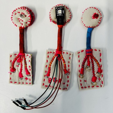
After I had constructed the pieces I had to figure out how to embed them into the brains. I sealed the pressure sensor wires underneath the LED units using heat tubes to keep it neat and as small as possible. Then I realised that all this conductive thread hanging out of the bottom looked like a hot mess so I decided to add little connector components to make it easy to connect on the outside of the inflatable as sewing it after sealing is probably playing with fire. I also stitched on the positive, negative and any colour names of the connection so I could see these after sealing. I also used little O Rings at the ends to make it easier to connect to crocodile clips
Pressure Sensor and LEDS
I had been testing these as I went both with the connections and with the LED but I wanted to test these final LEDs. Very simply if you connect the pressure sensor to the positive and negative connections you can see the brightness dim as its pushed. Both worked with this set up. The red LED is connected to the prototype pressure sensor so its not as sensitive but the green one is connected to the second one I made so you can see the difference easily. I need to program a simple code to make it brighter as you push but thats a later problem currently.
Pressure Sensor and RGB LED
Next job was to get the RGB LED working with the pressure sensor. From the lecture with Neo Pixels in wearables week I knew that different colours have different values so it was about trying to program these colour values to correspond to the analog values from the pressure. After trawling through various tutorials and trying a few things out I found the base of a code from robtillaart on the Arduino hub who had responded to a question. This was the base of my code as it really makes sense to me and it had great notation. It kinda worked at first with the 3rd pressure sensor but I needed to change the values to correspond to it more closely. After reading the values on the serial monitor I saw that the values I was gtting were mostly under 200. In order to make the range of colours more distinct I changed it so that the range of values would change the colour every 20 units. when I tested it it kinda worked but in a very chaotic order so I added a delay to the output of 100 and this made it a little clearer. I also added a few more colours in from the code above cause colours. I still think this code needs a little work and Its gonna be interesting to see how it behaves under extreme inflation. This can only really be tested when its actually inside and sealed in. Here you can see it in action.
The Code
//Setup all pins
int sensPin = A0;    // set the touch sensor (analog) input pin on Arduino
int redPin = 3;    // set the PWM (analog) output pin on Arduino controlling the red anode
int grnPin = 5;        // set the PWM (analog) output pin on Arduino controlling the green anode
int bluPin = 6;    // set the PWM (analog) output pin on Arduino controlling the blue anode

//Initialize variables
int redVal;         // pulse width variable for red anode
int grnVal;         // pulse width variable for green anode
int bluVal;         // pulse width variable for blue anode

void setup()
{
  pinMode(redPin, OUTPUT);   // set the LED pins as output
  pinMode(grnPin, OUTPUT);
  pinMode(bluPin, OUTPUT);
  Serial.begin(9600);
}

void loop()
{
  int val = analogRead(sensPin);           // read touch sensor values

  if (val < 20)
  {
    redVal = 255;  //red
    grnVal = 0;
    bluVal = 0;
  }
  else if (val < 40)
  {
    redVal = 0;  //green
    grnVal = 255;
    bluVal = 0;
  }
  else if (val < 80)
  {
    redVal = 0;  //blue
    grnVal = 0;
    bluVal = 255;
  }
  else if (val < 100)
  {
    redVal = 255;  //raspberry
    grnVal = 255;
    bluVal = 125;
  }
   else if (val < 120)
  {
    redVal = 0;  //cyan
    grnVal = 255;
    bluVal = 125;
  }
   else if (val < 140)
  {
    redVal = 255;  //magenta
    grnVal = 0;
    bluVal = 255;
  }
   else if (val < 160)
  {
    redVal = 255;  // yellow
    grnVal = 255;
    bluVal = 0;
  }
  else
  {
    redVal = 255;  //white
    grnVal = 255;
    bluVal = 255;
  }
  display(redVal, grnVal, bluVal);
  delay(100);  //delay
}

void display(int r, int g, int b)
{
  analogWrite(redPin, r);
  analogWrite(grnPin, g);
  analogWrite(bluPin, b);
}
Silcon Moulding Part 2
3D Printing Part 2
As a small break from the electronics (well almost), I needed to 3D print an Arduino case for myself as mine is getting a little bashed from all the work so I decided to print another design I had made from the heart cell cymatics. After casting the first 3D printed mould I felt that the box surrounding the image was too high so the silicon in this area was a bit thicker than I wanted so I prepared the image in exactly the same way as before although this time the inner curve was connected so I only needed to subtract 1 curve instead of 5 in the same Grasshopper definition. I reduced the scale of the box and also made the reduction in the extrusion of the other box so the difference is now 2.
I used exactly the same settings as I did for my first sucessful mould and the same process. I had a print time of 1hr 43mins and again I am very happy with the result as you can see below.
Casting Part 4
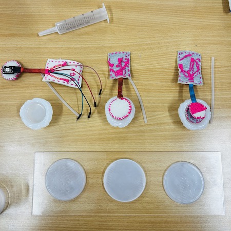
So here we are again. Firstly I used exactly the same technique as in casting part 1 to prepare and pour the silicon for my 3D printed mould. Next was the difficult part and that was enclosing the electronics in the brains. The repour I had done had sealed any obvious weak points and holes that I could see. I picked the best 3 brains and trimmed the edges so they where nice and clean and got the other parts I had poured to close the inflatables. Next I prepared the electronics and air pipes. I made slightly bigger gaps in the edge to be able to close the brain around the wires. I was pretty sure this was gonna be difficult so I prepared the area well for what I assumed correctly would not be the easiest pour.
The first 2 with the LEDs went surprisingly well but the 3rd one with the RGB led did not at all. Even though I had tested everything to see if it would all fit together nicely. I didn´t. I tried pushing it down by hand for ages but low and behold it was another hot mess. I knew that this one would need a repour anyway so I placed a book over the easier ones and decided to head home for dinner to come back 4 hours later and fix it.
Casting Part 5
4 hours later in the dead of the Blönduós night (extremely dead) I popped back in to check my moulds. One of them actually worked pretty well. There was definately a small hole somewhere but it actually inflated WOO HOO.
The second one with an LED also almost worked. It was losing a tiny bit of air around the wires but as I will have to recast anyway its not a problem.
Ant the one with the RGB LED is completely open as I suspected. This one has 2 more wires so its more to close.
In this final (I hope) casting I pored some more silicon on everything and hoped for the best. We will find out at the local review tomorrow....
I also closed up my 3d printed mould in the way I had done previously. Fingers crossed. I have also attempted to fix the broken gripper.
Results
3D Printed Moulds
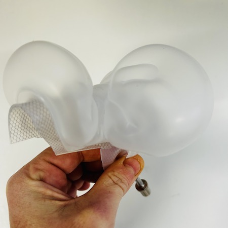
For the next one I realised that I had closed off one chamber so not completely sucessful but super cool anyway.
I really blew these up in the end and they made excellent grippers
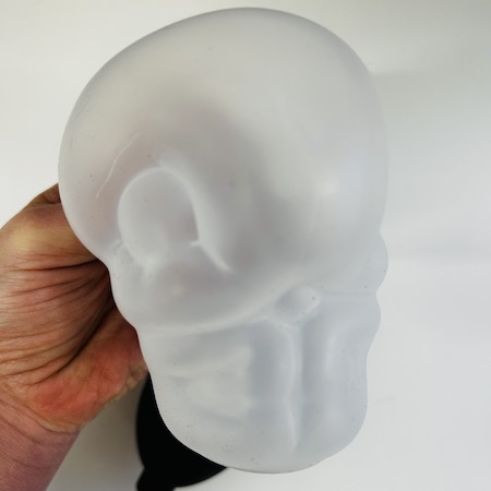
Inflatable Brains
The LED pressure sensors didnt seem to work but with a bit more time I´m sure I could figure it out. They also all leak air a little but at this point I´m happy with these results. They light up so go me.
The final one which I had zero hopes of working actually kinda worked yay. I still need to play with the values and it leaks a little but. I looks cool and that was my goal for the week.
Alumni Resources
Tools
Fabrication files
-
File: Grasshopper Definition ↩
-
File: 3D Model A ↩
-
File: 3D Model B ↩