08 Wearables
Research
Woo Hoo its wearables week and Ive really been looking forward to this. One of my first projects was to make the ultimate festival survival suit which had a pop out tent embedded into the skirt of the dress part, lights sewn into the hood and a wind up torch integrated into the arm of the jacket. I had also tried to make a circuit where I would charge the torch from movement so it has pleased me greatly to see the tech has caught up with my ideas from 2004.
Hussein Chalayan
The most influencial designer on my work through the years has to be Hussein Chalayan. His work capitivated me when I was younger. His designs were the first wearables I was aware of and I was lucky enough to see his show at the Design Museum in London for my 30th birthday. I spent hours in there staring closely at all the construction. I still love watching his old runway shows even today.
Hussein Chalayan from Jennifer Cipperly on Vimeo.
EJTECH
One of the other projects I really like altough not wearable as such, is from EJTECH. The Liquid Midi is an experimental modular textile interface using screen printed conductive textiles as a fader and a trigger for sonic interactions. I particularily love the way its printed giving an idea of the way it sounds as you play it.
SHIRT CIRCUIT
A really fun project I found was on Instructables was this fun wearable breadbord tee shirt by Manasvi Lalwani & Clement Zheng. I think it would be super fun to prototype all my circuit designs on this rather than an actual breadboard.
Day 1
Making a Driver Circuit
In electronics, a driver is a circuit or component used to regulate current flowing through a circuit to control another circuit or component, such as a high-power transistor. An amplifier, when integrated, can be considered as a driver circuit for loudspeakers, or a voltage regulator that keeps an attached component operating within a broad range of input voltages. It is usually integrated but we are using this particular circuit as an separate entity for prototyping.
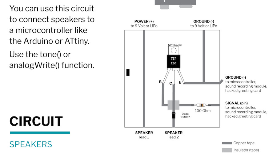 Driver Circuit Diagram.
We were to make this with cardboard but still had to use the Soldering Iron to attach our components to the copper tape in the curcuit. Its been a very long time since my last attempt at it and I was pretty bad at it as you can see below.
I also has to use solder to connect the pieces of tape due to the glue underneath to make sure it was conductive. Thankfully afterwards it all worked.
Tools and Materials
A Piece of Cardboard
Copper Tape
Insulating tape
NPN Bipolar TIP 120
1N4007 Diode
100 OHM resistor
Scissors
Pliers
Soldering Gun
Stand
Soldering Flux
Basic Arduino
Next stage was to follow the tutorial. I was so happy as for I think the first time ever, everything worked out. We learned how to connect our digital switches and show values (on or off /1 or 0) in the serial monitor as you can see below. The Serial Monitor is an essential tool within Arduino for comunication with the board so you can see the values and data that is being worked with.
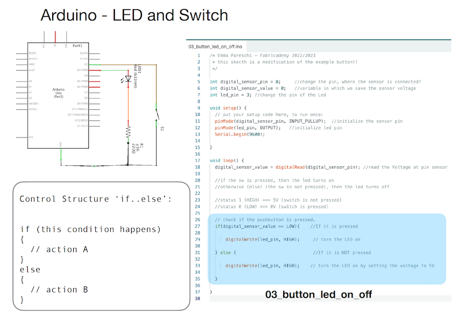 Slide Showing the Circuit Used and Code. Taken From the Lecture of Emma Pareschi.
We also went through a way of counting the number of presses on the switch using the code and displaying this in the serial monitor. By altering the code I was able to increase the reset count from 10 to 20.
Slide Showing the Circuit Used and Code. Taken From the Lecture of Emma Pareschi.
Electromagnets and Drivers
Here we learned about the circuit driver we had made earlier and about transistors. A transistor can act as a switch or gate for electronic signals, opening and closing an electronic gate many times per second. It ensures the circuit is on if the current is flowing and switched off if it isn't. This helps in having a separate power flow to what you get out of the arduino.
We also learned about electromagnetism, the physical interaction among electric charges and the electromagnetic field. For our next lesson we generated an electromagnetic field to make a flip dot using the driver circuit we had made earlier in the day. A flip dot is a magnet that changes direstion with a change in current direction. They are used in signs and can be controlled in matrixes much like leds.
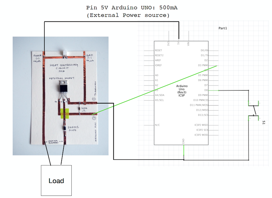 Slide Showing the Circuit Used to connect the electromagnet. Taken From the Lecture of Emma Pareschi.
Tools and Materials
Cardboard Circuit Driver.
9V Battery.
Crocodile Clips.
Arduino UNO R3.
Enamled Copper wire (substituted with cheap jewellery wire I had got in Solstene Grene).
A Square Magnet.
First we wound the wire around a pen. The instructions said 50 to 100 times but I only did 40 as the spring kept jumping off the pen. I then wound some of the wire aound to keep the coil in place. leaving two wires hanging down to connect to the battery.
- You can see the results below.
As you can see this was all pretty dangerous. I used a weaker magnet initially in the center of my coil and it flew across the room. You might have someones eye out with these which is why I suspect they are usually teathered by a thread. Also, the sparks you can see really didn´t sit well with me so I decided this wouldn´t be a route I would take for my actuators but fun to try.
when I got home I went through a big box of tiny electronic components I´d been given because I had zero idea of what was there. It was fun figuring out what they were and how they could be used. I found I had a 16/2 LCD screen and an infrared detector that I could possibly use to measure and display my pulse so that was my first mission for the next day. Well best laid plans and all that....
LCD Screen
A whole morning was spent trying to figure out how to get this screen I had working. I believed that this would be a handy interface to see the serial monitor functions as it turned out this was just frustrating beyond all belief.
- Here you can see my expectations of what I would achieve in the morning from one of the many tutorials I looked at.
 Basic Expectations of what I Could Acheive With the Display.
I had so many failures in this project that I learned alot from it heres the list of all the learning I did by failing alot...
Learning by Failing
Know Your Components
So I thought all components from all manufacturers were the same and this is actually not the case at all and it matters. After looking up the LCD screen and downloading the liquid Crystal Library I thought I was good to go. NOPE. I realised that my screen had an in built I2C component which basically means it needs less pins on the arduino (a good thing right)
OK, I found a load of tutorials on the 16/2 I2C LCD screen. I Manage to get it to light up so all good. Then it tells me in these tutorials that I have to download the liquid Crystal I2C library instead but theres loads of them and all the different tutorials have different libraries. they also said to download a library called Wire so I do that too. I endded up in the end with 2 different liquid crystal I2C menus that created a bunch of issues after because the arduino couldn´t figure out which one it should use. I ended up deleting all of them and only having the one I put in the link above.
Also, during this drama they all say that there´s different manufacturers and they all have different codes that you need in the code in order for you to program the thing. Cue an hour of squinting at tiny pictures of screens seeing if I could tell the difference between them. Then I figure out you can use an I2C Scanner to get the manufacturers code which turns out to be the most common one anyway (0x27).
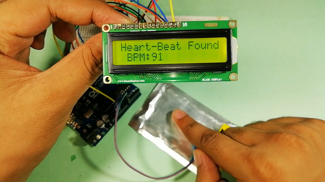
On a side project at the same time I am trying to get the pulse sensor working. The component I have is the KY-039 which is the least acturate of the ones on the market by the looks of it. Anyway the more popular ones come with all the code for making a heart beat wave and BPM. This one didnt and of course it doesnt work with the code of the one from another manufacturer.
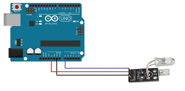
Arduino with the KY-039.
Although I did eventually get this working in the end the results were so wild that either I should speak to my Cardiologist right now or just give up so I gave up.
Check Your Connections
So it turns out after all of this that most of the time the arduino came up red it said unknown port selected. Now I had it on and the lights were on and it said Arduino Uno in the box at the top of the sketch. I thought the problem must be in the code and I am just at the absolute end of my teather at this point and it turns out...
IT WASN´T CONNECTED!!! ahhhhhhhhhhhhhhhhhhhhh.........
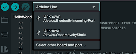
The Failure Looks Like This
Here you see that the box says Arduino Uno but this IS NOT YOUR ARDUINO UNO* Honestly, why would it be, RIGHT!!! Now I always select the menu and drop down to make sure its the particular arduino uno I´m using.
After all these hours of work I still have nothing to show for it at this point. I finally got the screen working using the inbuilt Hello World program built into the I2C library and I was so relieved I actually put a swear word on it. As an angry Scot I am not even sorry.
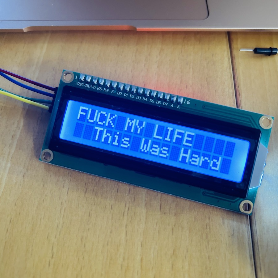 The LCD Screen finally working.
Then immediately it was lecture time. I was following but when it cam to the neo pixels part I realised that the ones I had could not be tested on the bread board and I didn´t have time to sew them. together. I tried to use some other ones and the program just wouldn´t work again. I decided that the only thing to do was to leave the studio and have a beer in the house and sit down and try to get something done.
When I got home I set up my stuff again and I kept getting the same message over and over so I finally decided to google this error code.
AVRDUDE: STK500_RECV(): PROGRAMMER IS NOT RESPONDING
I watched this amazing video about this AVRDUDE who in my opinion is not a dude at all. This made me realise that
THE USB HUB WAS NOT CONNECTED PROPERLY THIS TIME!!!!!! ahhhhhhhhhhh.
Since watching this and understanding this error code my life has been easier in this sense at least. Going through all this made me realise that I would of solved all of this if I had just understood the code better.
Know How To Program
E Texiles week was a bit more focused on the making of the pieces for me and as I didn´t have the Velostat I just kinda trailed off in the programming side of it and that fact has become apparent now. I sat for the rest of the night going through the first 12 tutorials from Paul McWhorter on youtube. He is like a sweet old teacher and slowly, by following along, I had made a SOS Morse Code Program, a Binary Clock and other programs from scratch. This vastly improved my understanding of the language.
- Below you can find the tutorial series I used.
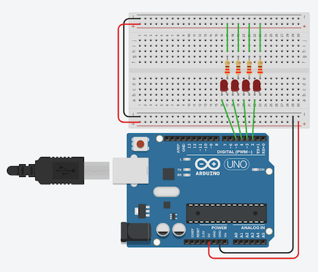
I became way more confident by actually making something work. Here I used the cicuit wired like this below to count to 15 in binary. Small victories. The code I made is very long but it was to show us how the code works and how we can replace these long codes later with variables.
int pin2=2;
int pin3=3;
int pin4=4;
int pin5=5;
int waittime=1000;

    void setup() {
        pinMode(pin2,OUTPUT);
        pinMode(pin3,OUTPUT);
        pinMode(pin4,OUTPUT);
        pinMode(pin5,OUTPUT);
    }

    void loop() {

        digitalWrite(pin2,LOW);
        digitalWrite(pin3,LOW);
        digitalWrite(pin4,LOW);
        digitalWrite(pin5,LOW);
        delay(waittime);

        digitalWrite(pin2,LOW);
        digitalWrite(pin3,LOW);
        digitalWrite(pin4,HIGH);
        digitalWrite(pin5,LOW);
        delay(waittime);

        digitalWrite(pin2,LOW);
        digitalWrite(pin3,LOW);
        digitalWrite(pin4,HIGH);
        digitalWrite(pin5,HIGH);
        delay(waittime);

        digitalWrite(pin2,LOW);
        digitalWrite(pin3,HIGH);
        digitalWrite(pin4,LOW);
        digitalWrite(pin5,LOW);
        delay(waittime);

        digitalWrite(pin2,LOW);
        digitalWrite(pin3,HIGH);
        digitalWrite(pin4,LOW);
        digitalWrite(pin5,HIGH);
        delay(waittime);

        digitalWrite(pin2,LOW);
        digitalWrite(pin3,HIGH);
        digitalWrite(pin4,HIGH);
        digitalWrite(pin5,LOW);
        delay(waittime);

        digitalWrite(pin2,LOW);
        digitalWrite(pin3,HIGH);
        digitalWrite(pin4,HIGH);
        digitalWrite(pin5,HIGH);
        delay(waittime);

        digitalWrite(pin2,HIGH);
        digitalWrite(pin3,LOW);
        digitalWrite(pin4,LOW);
        digitalWrite(pin5,LOW);
        delay(waittime);

        digitalWrite(pin2,HIGH);
        digitalWrite(pin3,LOW);
        digitalWrite(pin4,LOW);
        digitalWrite(pin5,HIGH);
        delay(waittime);

        digitalWrite(pin2,HIGH);
        digitalWrite(pin3,LOW);
        digitalWrite(pin4,HIGH);
        digitalWrite(pin5,LOW);
        delay(waittime);

        digitalWrite(pin2,HIGH);
        digitalWrite(pin3,LOW);
        digitalWrite(pin4,HIGH);
        digitalWrite(pin5,HIGH);
        delay(waittime);

        digitalWrite(pin2,HIGH);
        digitalWrite(pin3,HIGH);
        digitalWrite(pin4,LOW);
        digitalWrite(pin5,LOW);
        delay(waittime);

        digitalWrite(pin2,HIGH);
        digitalWrite(pin3,HIGH);
        digitalWrite(pin4,LOW);
        digitalWrite(pin5,HIGH);
        delay(waittime);

        digitalWrite(pin2,HIGH);
        digitalWrite(pin3,HIGH);
        digitalWrite(pin4,HIGH);
        digitalWrite(pin5,LOW);
        delay(waittime);

        digitalWrite(pin2,HIGH);
        digitalWrite(pin3,HIGH);
        digitalWrite(pin4,HIGH);
        digitalWrite(pin5,HIGH);
        delay(waittime);
    }
Code Know How
- Declare your pieces in play first. In this case int for integer or whole number. For example int pin2=2 is declaring that pin2 is the name of the component on pin2 of the arduino.
- void setup() is the area where you declare what these pins are doing so in this example
void setup() {
pinMode(pin2,OUTPUT);
has pinMode that configures the specified pin to behave either as an input or an output. Here the LED in this case on pin 2 of the Arduino is an output. - void loop() is the area that is doing the work and its contained within a loop that repeats. In this example
void loop() {
digitalWrite(pin2,HIGH);
has digitalWrite that is the code that write a HIGH or a LOW value or on/off to a digital pin. Here the LED on pin 2 is on at 5V as this is a digital value so LOW would be 0V or off. - Curly Brackets are important. This opens and closes the code
- Capitals are important. The program is very case sensitive.
-
Remember the Semi Colon at the end of every line. the program would run without it.
-
Below is the wiring diagram for the program I wrote.
- Here is the binary clock counting from 1 to 15.
Day 2
The Hearty Party
Brimming with new found confidence and knowledge I really thought alot about my final outcomes for the week. I had initally planned to make the actuators responsive to my pulse but thinking about it there is loads of tech companies with way better wearable monitoring systems that I can do with my 2 weeks of programming and electronics experience. I started to look at the cyanatics again and ways of playing sound frequencies into the heart in theraputic ways but I was overwhelmed by new age hippy websites and it just all didn´t feel like me. Thats when I came up with the idea of a Hearty Party a wearable disco party for the chest area. I had basic ideas for it.
- Embed a speaker into the piece.
- Program a light show.
- Add a lazer because I have lazer module and LAZERS ARE EPIC.
I have a really basic old and fun yellow hoody I have decided to work on in this project. I was going to make something modular and piece it together but this hoody material is strong so easy to attach things to. Its bright and colouful and fun, just like I would like to project to be and its upcycling so good for the world.
Sound
My plan was to program Dont Go Breaking My Heart by Elton John and Kiki Dee into Arduino to play on my chest embedded into the hoodie. I actually had a really stressful time seeing Elton John in Leipzig 3 days before my heart attack. We got stuck on the Autobahn and arrived really late, had to climb a million stairs to get to our seats, missed most of the good songs and then had to sit through Candle in the Wind. Its been a standing joke that Elton John tried to kill me. Also, this song seemed to be playing all the time when I was in cardiac rehab, oh the irony. I thought it would be a fitting tune for the Hearty Party. This I thought would be easy just to get a basic speaker working and program it. I was so very WRONG!
The speaker just would not work. I tried every possible combination of circuit imaginable. I broke the wire off and soldered it back on and basically wasted an entire day on it. We only have 2 small 8ohm speakers and no amplifiers so I really thought my plan would never work at this point. You can imagine the frustration I felt when I had spent all the time and energy failing for learning all day the day before in the ways I descibed just for the materials not to work the next day.
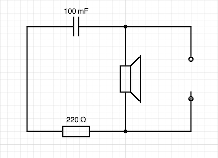
I had a mini strop and went for another beer in the house and then after reading this tutorial by Starting Electronics on a slightly different set up, I noticed that the resistor had been changed to a capacitor instead and by some miracle a stratchy noise finally came out of it. I can assure you this was the best noise I have ever heard. It was at this point I gave up for the day. I will be returing to it to try and firstly make it sound better. Then I need to program the tune and then It needs to go into the hearty party but at least now there is hope.
- You can here this awful squeaky rendition of Twinkle Twinkle Little Star below.
The tutorial and code I used to make this painful sound is here. I will be using this as my base when I return to program the music.
Arduino tutorial special thanks and copyright 2018 Code and Make (codeandmake.com)
Day 3
Neopixel Party Lights
Now it´s time to work on the neopixels. The WS2812 Integrated Light Source (or NeoPixel) is a full-color LED. Red, green and blue LEDs are integrated alongside a driver chip into a tiny surface-mount package controlled through a single wire. They can be used individually, chained into longer strings or assembled in patterns.
Construction
I only have 4 of the sewable flora V2so I decided to embed them into the hood to make the best use of them. Its pretty simple to join them together by the looks of it. You sew the data line which you can see with the arrows printed on the pixel and then you connect the positive sides together then again with the negative.
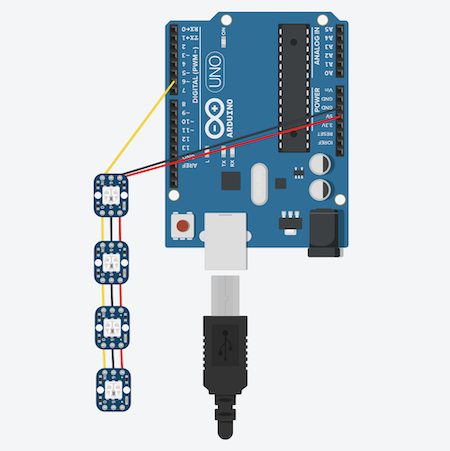
After testing that they work one by one using the code 01_neopixel_v1 from Emma Pareschis lecture. I decide to just dive in and sew them in. I decided to unpick the hood so I could make the sewing only visable on the inside. It just is so much neater in my opinion.
- This video was extremely helpful in best practices when it comes to sewing this.
as I worked it was very important to check the connectivity between the points as you go. I did two lines in every row of stiching just to make sure everything was connected. I also followed the trick of tying the knots then adding a spot of nail polish. (Thanks to Birdie for the use of her yellow.)
Sewing them in was not without its issues. I had burned through my 2 ply conductive thread in E Textiles week and we were only provided with 3 ply which is alot more challenging to sew through the tiny holes of the neopixels. I ended up having to remove one strand to get the thread through the needle. This obviously meant that the metalic thread, already a curse to embroiderers, was brittle and prone to making little loops in the line that could possibly be prone to shorts.
When I had my 3 lines sewn through the pixels its important to..
CHECK THE CONDUCTIVITY BETWEEN CONNECTIONS
As I wouldn´t say the sewing job I did was the neatest due to the brittle threads, I decided to add some simple pink wool, cotton blend running stitches in between the conductive lines to add a little layer of non conductive security between the lines.
So now it was time to check that it worked. It didn´t. I tried with testing all the individual pixels again and some worked and some didn´t. I was just about to cry again when I thought about trying some of the other sketches that Emma had provided us and Voila.... Rainbow worked!!!!
If I have time later I will play with the code a bit but after checking the connections one more time and adding poppers to the input line I closed up the hood by hand and its still working. Finally a win!!!
The Code
- Here is the code I used...
//Emma Pareschi 2020
//Adaptation of the example Standtest

#include <Adafruit_NeoPixel.h>

#define LED_PIN    6

// How many NeoPixels are attached to the Arduino?
#define LED_COUNT 4

// Declare our NeoPixel strip object:
Adafruit_NeoPixel strip(LED_COUNT, LED_PIN, NEO_GRB + NEO_KHZ800);

uint32_t off = strip.Color(0, 0, 0);
int num_rainbow = 5;

void setup() {

  strip.begin();           // INITIALIZE NeoPixel strip object (REQUIRED)
  strip.show();            // Turn OFF all pixels ASAP
  strip.setBrightness(50); // Set BRIGHTNESS to about 1/5 (max = 255)
}

void loop() {

  rainbow(10);             // Flowing rainbow cycle along the whole strip
  strip.fill(off, 0, 10);  // turn the strip off
  strip.show();  //display the color
  delay(1000);

}

// Rainbow cycle along whole strip. Pass delay time (in ms) between frames.
void rainbow(int wait) {
  // Hue of first pixel runs 5 complete loops through the color wheel.
  // Color wheel has a range of 65536 but it's OK if we roll over, so
  // just count from 0 to 5*65536. Adding 256 to firstPixelHue each time
  // means we'll make 5*65536/256 = 1280 passes through this outer loop:
  for(long firstPixelHue = 0; firstPixelHue < num_rainbow*65536; firstPixelHue += 256) {
    for(int i=0; i<strip.numPixels(); i++) { // For each pixel in strip...
      // Offset pixel hue by an amount to make one full revolution of the
      // color wheel (range of 65536) along the length of the strip
      // (strip.numPixels() steps):
      int pixelHue = firstPixelHue + (i * 65536L / strip.numPixels());
      // strip.ColorHSV() can take 1 or 3 arguments: a hue (0 to 65535) or
      // optionally add saturation and value (brightness) (each 0 to 255).
      // Here we're using just the single-argument hue variant. The result
      // is passed through strip.gamma32() to provide 'truer' colors
      // before assigning to each pixel:
      strip.setPixelColor(i, strip.gamma32(strip.ColorHSV(pixelHue)));
    }
    strip.show(); // Update strip with new contents
    delay(wait);  // Pause for a moment
  }
}
Day 4
Laser
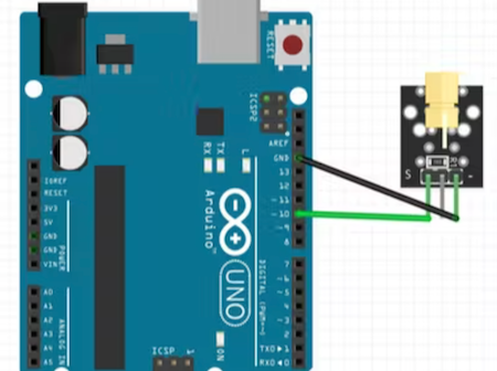
I realised in my mix bag of stuff I had laser component, the KY-008 Laser Module. Its super cheap and basically a laser pointer so the only thing you can really do with it is flash it on and off etc. Its pretty simple to connect as it only uses the outer 2 of its 3 pins, ground and out. I had a good look around for interesting projects ans found some really cool stuff out there. Especially this one where the laser is transmitting data made by iforce2d on youtube.
- Here you can see the wiring I used.
Construction
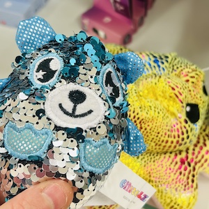
One problem with alot of these was that I didn´t have a laser reciever so I started playing around with materials I could use with it. I thought about attaching motors to it to create a kind of light show. but it was about wearables so its already a pretty bulky thing. Then I thought about just making a big reflective surface for it to get more bang for your buck out of the light. As i live in a tiny village with nothing in it especially on a Saturday, I went to the local shop and found a pretty gross double sequinned kids toy. I killed it.
- Before and After

Obviously being the only sequinned material in Blönduós there wasnt much of it so I hacked together into a kinda discoball toggle feel and and sewed that onto the toggle of the hood. I´m super happy with how this test turned out too.
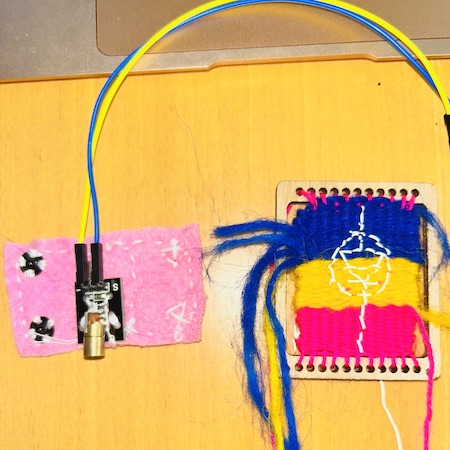
Now it was time to embed the laser. I decided to make it a removeable toggle that could attach to the hoodie string but could be removed and used on other things if needed. I attached it, (thankfully it had holes for sewing) to a piece of felt then sewed a pair of poppers on that. Then I used a mini loom to make a wee blanket for it to cover the module on the base felt. I sewed in the circuit diagram symbol in retroreflective thread and then pieced this together to make the final unit.
The Code
I decided to keep the code for this very simple. I didn´t feel that blinking it on and off was going to make any difference so its super easy. Just connect the S pin to 10 and the ground to GND and boom, Laser.
int laserPin=10;

void setup ()
{
  pinMode(laserPin, OUTPUT);
}

void loop () {
  digitalWrite(laserPin, HIGH);
}
Day 5
Sound Part 2
After all the fun with lights, now its time to get the speaker working properly. I broke the wire off it again so Louise suggested just soldering on better leads for both of the speakers I was trying to work with. After doing this it was so much easier to work with them.
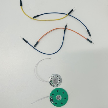
It turns out the speaker I was using initally just sounded terrible. I think I might of even blown it, but the larger green one sounded pretty good. I added a resistor just in case to prevent anymore speaker death. I also tested different capacitors with it to see it in made much of a difference, it didn´t really so great I had a circuit that kinda works with Twinkle Twinkle.
- Here is my circuit diagram. I cant say if this is exactly the right way to do this but it works so I will take it.
Construction
Now I had a circuit, how do you make it wearable?
The speaker itself is not sewable so I looked again at a fabric speaker I really liked on Kobakant that I would of tried to make if we had any magnets for it.
I looked into if adding and extra copper coil into it would effect the speaker and maybe amplify it but I didn´t think so. I just attached the speaker in this style. Again I decided to make it modular so it could be attached and removed easily. I used one of my old sample off cuts with the pink yarn I have used throughout the project to stitch.
I have made a point not to make heart shapes in my project so far. but the way the wires were soldered on and the way they wanted to lie just lent itselt to this shape. I couched them onto the piece then used conductive thread to sew in the capacitor and the resistor according to the circuit diagram. I found some metal rings that I thought would made easier connection points to the arduino and I added these to the center of each half heart and connected these to the circuit with conductive thread.
I was testing the circuit at every stage to make sure it was all conductive. when I was done I tested it with twinkle twinkle again and YES! Its actually working!!!
- Below is the video of the working speaker.
The Code
Now this code was not simple as it involved making music, well at least a very poor attempt at it. It was time to dig out the Elton John again. I aske dmy boyfriend, who reads music, to help with with the first notes. He gave me the first line. Turns out the tricky thing is the timing. Luckily the code had really good instructions inbedded into it.
-
Some Notes...
-
The pin on the arduino used is 12.
- The BPM(beats per minute) of Don´t go Breaking my Heart is 131bpm but I raised it to 141 I still think its slow but hey ho.
- the individual notes look like this {47,4} The first number is the note number on the 88 key keyboard. The second number is the note length.
- A zero as the first number is a silence.
- 1 in the second number is the longest note, 4 beats.
- 8 in the second number is the shortest note, 0.5 beats
- I didn´t touch the rest of the code.
- I am not musical.
/*
 * Copyright 2018 Code and Make (codeandmake.com)
 *
 * Permission is hereby granted, free of charge, to any person obtaining a copy
 * of this software and associated documentation files (the "Software"), to deal
 * in the Software without restriction, including without limitation the rights
 * to use, copy, modify, merge, publish, distribute, sublicense, and/or sell
 * copies of the Software, and to permit persons to whom the Software is
 * furnished to do so, subject to the following conditions:
 *
 * The above copyright notice and this permission notice shall be included in
 * all copies or substantial portions of the Software.
 *
 * THE SOFTWARE IS PROVIDED "AS IS", WITHOUT WARRANTY OF ANY KIND, EXPRESS OR
 * IMPLIED, INCLUDING BUT NOT LIMITED TO THE WARRANTIES OF MERCHANTABILITY,
 * FITNESS FOR A PARTICULAR PURPOSE AND NONINFRINGEMENT. IN NO EVENT SHALL THE
 * AUTHORS OR COPYRIGHT HOLDERS BE LIABLE FOR ANY CLAIM, DAMAGES OR OTHER
 * LIABILITY, WHETHER IN AN ACTION OF CONTRACT, TORT OR OTHERWISE, ARISING FROM,
 * OUT OF OR IN CONNECTION WITH THE SOFTWARE OR THE USE OR OTHER DEALINGS IN THE
 * SOFTWARE.
 */

/*
 * A simple project that demonstrates how to make music using an Arduino.
 *
 * This code accompanies the following tutorial: https://youtu.be/Z1YvIFUIhLs
 */

// Pin to which an 8 Ohm speaker is connected (use a 150 - 220 Ohm resistor)
#define speakerPin 12

// Tempo (beats per minute)
#define bpm 141

// Gap between notes. This is expressed as percentage of time between 2 beats.
#define noteGapPercentage 10

/*
 * 2D array containing the notes to be played
 * A note comprises of two values:
 *  * The first value determines the frequency of the note.
 *    This is expressed as the number of a key on an 88-key piano (1 - 88)
 *    A number outside this range can be used (e.g. 0) to create a gap
 *  * The second value determines the duration:
 *    * 1 represents a whole note (spans 4 beats)
 *    * 2 represents a half note (spans 2 beats)
 *    * 4 represents a quarter note (spans 1 beat)
 *    * 8 represents an eighth note (spans 0.5 beat)
 *      etc.
 */
uint8_t notes[][2] = {
  {49,4}, {49,4}, {49,4}, {49,8}, {0,8}, {49,4}, {47,4},
  {45,8}, {0,8}, {45,1}, {0,4}, {50,4}, {50,4}, {50,4},
  {0,8}, {49,4}, {50,4}, {49,8}, {0,8}, {49,1}, {0,4},
  {49,4}, {49,4}, {49,4}, {49,8}, {0,8}, {47,4}, {49,4},
  {45,8}, {0,8}, {45,1}, {50,8}, {0,8}, {50,8}, {0,8},
  {50,8}, {0,8}, {50,4}, {52,4}, {49,8}, {0,8}, {45,1}
};

// Time between two beats in microseconds (equal to length of a quarter note)
#define beatDuration (60.0 / bpm) * 1000000L

// Time of the gap between two notes in microseconds
#define noteGap beatDuration * (noteGapPercentage / 100.0)

void setup() {
  // Set the speakerPin as an output
  pinMode(speakerPin, OUTPUT);

  // Iterate over the notes array
  for(int i = 0; i < (sizeof(notes) / sizeof(*notes)); i++) {
    // pass the key number and note type
    playNote(notes[i][0], notes[i][1]);
  }
}

/*
 * Plays an individual note.
 *
 * keyNumber - The key number (1 - 88)
 * noteType - The note type (1, 2, 4, 8, etc.)
 */
void playNote(uint8_t keyNumber, uint8_t noteType) {
  long halfPeriod = getPeriodForKey(keyNumber) / 2;
  long noteDuration = beatDuration * (4.0 / noteType);
  long elapsed = 0;

  // While we have a note to play
  while(halfPeriod > 0 && elapsed < (noteDuration - noteGap)) {
    // Set speakerPin high for half of the period
    digitalWrite(speakerPin, HIGH);
    wait(halfPeriod);

    // Set speakerPin low for half of the period
    digitalWrite(speakerPin, LOW);
    wait(halfPeriod);

    // Update the amount of time that has elapsed
    elapsed += halfPeriod * 2;
  }

  /*
   * Gap between notes. Calculated using 'elapsed' to minimise timing errors
   * and ensure that the correct gap occurs whenever getPeriodForKey() returns
   * zero.
   */
  wait(noteDuration - elapsed);
}

/*
 * Returns the period for a key or zero for key numbers outside the range of 1 -
 * 88.
 *
 * keyNumber - The key number (1 - 88)
 */
long getPeriodForKey(uint8_t keyNumber) {
  // If the key is between 1 and 88
  if(keyNumber >= 1 && keyNumber <= 88) {
    // Return the period (one second divided by the frequency of the key)
    return 1000000L / (pow(2.0, (keyNumber - 49.0) / 12.0) * 440.0);
  }

  // Otherwise return zero
  return 0;
}

/*
 * Delay for a number of microseconds. This is necessary because
 * delayMicroseconds() has an upper limit.
 *
 * us - The delay in microseconds
 */
void wait(long us) {
  // First delay for the number of whole milliseconds using delay()
  delay(us / 1000);
  // Then delay for the remainder of microseconds using delayMicroseconds()
  delayMicroseconds(us % 1000);
}

void loop() {
  // Not used. Music will play once.
}
Final Piece

If I had a bit more time I would of had the tune a bit better. I also embedded my analog sensor from e textiles week onto the other toggle of the hoddie hoping I would have time to incorporate this into the speaker circuit but I´m out of time. Luckily all of this stuff is actually well made and can be added to.
Considerations
I need to figure out how to get all the code to work together or buy 3 AT Tinys to run everything but with the right stuff my plan is to wear it to a big warehouse party in December and have a Wee Hearty Party!