5. E-textiles
This week we have learned how to apply technology to textiles. We have started with some basic knowledge of what electricity is and its rules, in order to be able to produce our own sensors and generate a circuit programmed with Arduino.
Inspiration
There are many inspiring works related to this theme. I highlight these two because I feel that they give an emotional component to a fabric or a garment that could go unnoticed a priori. I am very interested in seeing how we can give different qualities to the textile until it becomes something purely sensory.
Musical Jacket by MAGGIE ORTH
The Musical Jacket is a wearable stand-alone musical instrument. It contains a wearable MIDI synthesizer, batteries, a fabric data, power and audio bus, and an embroidered keypad.
A fabric that remembers by LAURA DEVENDORF
Electronic Basics
Electricity travels from the power (+) side of the battery to the positive LED leg then from the negative LED leg to ground (-).
Important concepts:
- Circuit: a path for elecytricity to flow throug
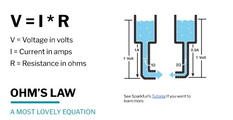
- Voltage: electrical pressure between two points. VOLTS, V.
- Current: the flow of electrons measured in Amps. AMPS, I.
- Resistance: The amount of material that resists the flow of current. OHMS, R.
RULES FOR ACTIVE CIRCUIT:
- Electrical energy always follows the path of least resistance to ground.
- All electrical energy in the circuit must be used.
- Different components play a different role in the system of the circuit.
DIGITAL Circuit
A digital circuit is one that handles information in binary form, that is, with values of "1" and "0", ON/OFF.
MATERIALS:
- Non Conductive Fabric
- Non Conductive Thread
- Conductive Thread
- Safety Pins
- 3V Battery
- LED light
- Embroidery frame
- Sewing Needle
As seen in the video, two poles come out of the LED, the negative and the positive pole. Powered by the 3V battery, once the two pins come into contact, the LED lights up.
DIGITAL AND ALSO ANALOG SENSOR
This bend sensor actually reacts (decreases in resistance) to pressure, not specifically to bend. But because it is sandwiched between two layers of neoprene (rather sturdy fabric), pressure is exerted while bending, thus allowing one to measure bend (angle) via pressure.
Resistance decreases as bent and more contact is made.
In this case, if I join it from the sides it is digital but if I apply pressure to the center it is analog.
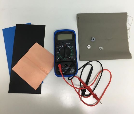
MATERIALS:
- Neoprene
- Conductive Thread
- Copper strip
- Velostat
- Multimeter
- Scissors
- Pen
PROCESS:
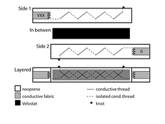
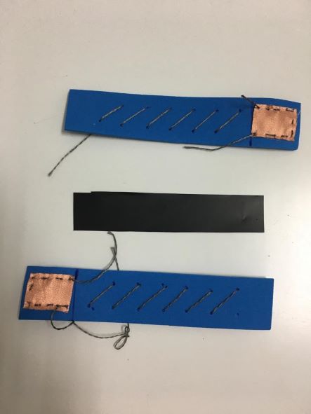
- Trace the stencil. After cutting out the neoprene pieces, trace the stencil to them. Fuse tabs of conductive fabric to either end.
- Sew with conductive thread. Thread a needle with conductive thread and stitch along the stencil pattern until you reach the tab of conductive fabric. Stitch the conductive thread to the conductive fabric with a few stitches to make good contact. Repeat for both sides.
- Velostat. Layer the neoprene with the conductive traces inwards so that the stitches criss-cross. The Velostat goes in between.
- Close. Sew the sensor together around the edges making sure not to sew too tight.
- Test. To make sure your bend sensor is working. Connect either end to a multimeter and set to measure resistance (ohm). Your initial resistance should lie around 2K ohm and should sink to about 100 ohm when pressured by pushing down hard.
ANALOG SENSOR
Paper + Aluminum Fpil Pressure Sensor
An analog circuit studies systems whose variables vary¡ies continuously in time and can take infinite values.
MATERIALS:
- A piece of Velostat
- Aluminum foil
- A sheet of paper
- Stick glue
- Scissors
- Multimeter
PROCESS:
- Cut 5cm x 5 cm piece of velostat, depending on your velostat sheet size.
- Cut off the paper that is double the height os velostat piece.
- Cutt off a strip of aluminum foil. This will determine the sensing area.
- Place the aluminum foil piece inside the folded paper base.
- Place the velostat in between the paper and fold it. Place the crocodile clip on end of each pieces of the aluminum foil.
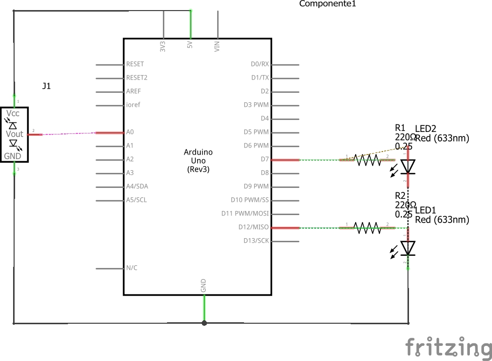
ARDUINO + SENSOR ANALOGIC + 2LED + 2 RESISTANCE
MATERIALS:
- Analog Sensor
- 1 LED (5mm) + 1 LED (10mm) INPUT
- RESISTORS OF 110 Ohm. One for each LED
- DATABOARD
- ARDUINO
- 5 PIN wires
GOAL:
Depending on the sensor’s lecture, we wanted to light up one LED or other.
HOW TO CODIFY ARDUINO
- I assign Pines to two LEDs.
- I assign Pin to the soft Sensor.
- I generate a variable that saves the lecture from the sensor in cm.
- I start the series communication and I define PinMode from the LEDs as an OUTPUT.
- I ascribe the following functioning to the LEDs: we use IF and ELSE to communicate that, if there is a value greater than 10 from the sensor, LED1 will turn on and, in consequence, LED2 will turn off.
- I mark a “delay” of 1000 (one thousand), which corresponds to 1 second.
int softsensor = A0; // Pin del soft sensor
                    // outside leads to ground and +5V
float lecsen = 0;  // variable to store the value read
float maplecsen = 0;// variable del valor del mapeo
int LED1 = 7;
int LED2 = 12;

void setup() {
  Serial.begin(9600);           //  setup serial
pinMode (LED1,OUTPUT);
pinMode (LED2,OUTPUT);

}

void loop() {
lecsen = analogRead(softsensor);  // read the input pin
maplecsen = map(lecsen, 0, 1023, 0, 20); // Mapeo del los valores máximos y minimos.

if (maplecsen > 10){
  digitalWrite(LED1, HIGH);
 digitalWrite(LED2, LOW);
}
else
{digitalWrite(LED2,HIGH);
digitalWrite(LED1, LOW);}


Serial.print(lecsen);          // debug value
Serial.print("   ---   ");
Serial.println(maplecsen);// imprimo vslor de lectura del sensor y su equivalente una vez mapeado.

delay(1000);

}
Arduino + Analogic Sensor + 2LED
Sensors applied to textile
To finish, I apply the analog and digital sensor to the textile and check the operation. As we can see, in the digital sensor I have to apply more pressure since the resistance is greater so that the LED turns on.