8. Wearables
This week we’ve dived deep into the electronic world. Using as a base the e-textiles knowledges, it has been quite enriching for me to be able to look further into the matter. For me, the technology world is a real discovery and it fascinates me to observe the capacity it has to improve our everyday life. The benefits are infinite and can be extrapolated to other areas.
It is possible to give a new and exciting addition to a textile, such as sound, movement or visual attributes.
I dedicate part of my laboral life to the sanitary area and I believe that these textiles are (or could be) a great addition to it, as it could cover certain unattended necessities.
Inspiration
Ying Gao

Yves Béhar´s Aura Power
Ying Gao | Yves Béhar´s Aura Power
ACTUATORS: VISUAL, SOUND, MOTION
For this week we have to create a sample using Arduino with an input and an output, using hard-soft connection solutions and battery. At the same time, we have to create 2 actuators samples and test them with Arduino. We can choose the following actuators; Visual, Sound, and Motors.
On this occasion we’ve worked on teams. My colleague Paula and I have chosen to work with the visual and sound actuators. Within the visual actuators, we’ve worked with LEDs and NEOPIXELs.
SOUND ACTUATOR (SPEAKER)
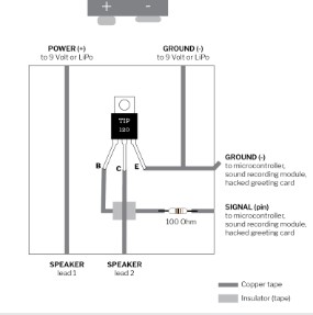
CIRCUITO MOSFET
We created the circuit taking as a reference Emma’s tutorial. Every actuator works differently, depending on a different circuit and this would be the one that corresponds to the Speaker. We incorporate a transistor to the circuit that allows us to control the voltage. There are different type of transistors, the one we used was N-Channel, a type of Mosfet. The transistor has three legs: G (gate), D (drain) and S (Source).
MATERIALS to create the circuit
- Copper straps
- Velostat
- Transistor
- Battery
- Resistance
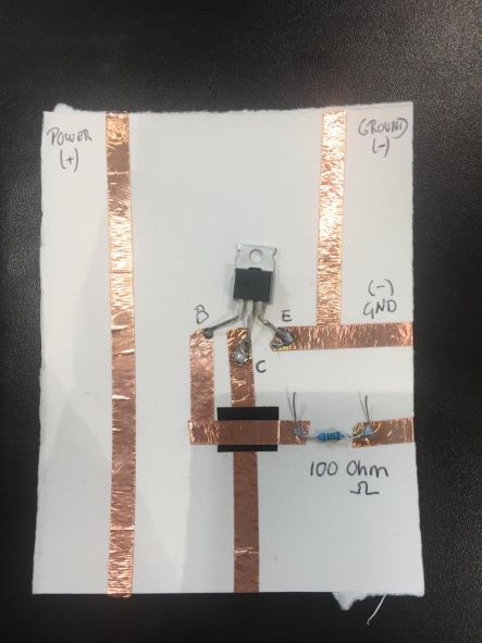
We had trouble to manage the power flowing all over the circuit. As you can see in the video, once we programmed the speaker in Arduino we verified (with the multimeter) that the signal adjusted to the programmed pace in Arduino. When we measured with the multimeter, no current was seen flowing after the resistance.
We did not manage to solve the problem.
VISUAL ACTUATOR (LEDS)
(2 LED INPUT + DISTANDE SENSOR HC-SR04 OUTPUT + ARDUINO)
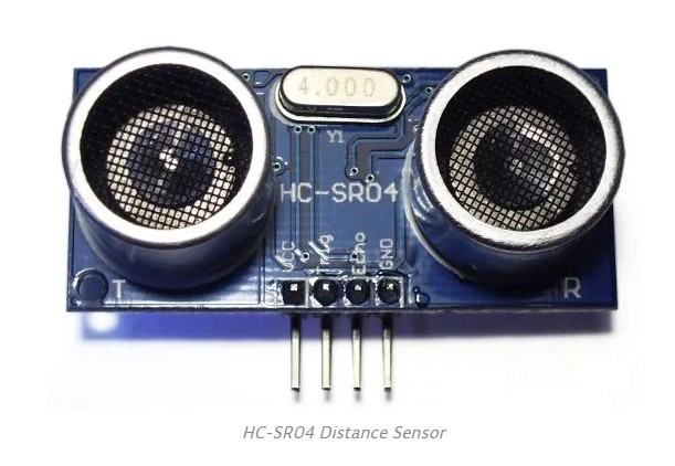
This sensor provides between 2 and 400cm of ultrasonic distance measuring. Each module HC-SR04 includes an ultrasonic transmitter, a receiver and a control circuit. This sensor contain 4 pines:
- VCC (Power)
- Trig (Trigger)
- Echo (Receive)
- GND (Ground)
In order to communicate with the sensor, I installed, through the Arduino library, the sensor codification.
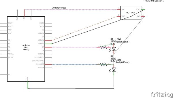
MATERIALS:
- DISTANCE SENSOR (HC-RO04) OUTPUT
- 1 LED (5mm) + 1 LED (10mm) INPUT
- RESISTORS OF 110 Ohm. One for each LED
- DATABOARD
- ARDUINO
- 8 PIN wires
GOAL:
Depending on the sensor’s lecture, we wanted to light up one LED or other.
HOW TO CODIFY ARDUINO
- I assign Pines to two LEDs.
- I assign Pines to Distance Sensor.
- I identify the pines form the sensor.
- I generate a variable that saves the lecture from the sensor in cm.
- We start the series communication and we define PinMode from the LEDs as an OUTPUT.
- We ascribe the following functioning to the LEDs: we use IF and ELSE to communicate that, if there is a distance superior to 10cm from the sensor, LED1 will turn on and, in consequence, LED2 will turn off.
- We mark a “delay” of 1000 (one thousand), which corresponds to 1 second.
ARDUINO CODE
int baudrate = 9600;

int triggerPin = 5; // el data Trigger del sensor se aloja en el Pin 5
int echoPin = 6; // el data Echo del sensor se aloja en el Pin 6

int LED1= 12;
int LED2= 7;

float lecsen= 0; // lectura del sensor en esta variable (0)
float maplesen= 0;  // variable del valor del mapeo

SR04 sensor(triggerPin, echoPin);

double cm;

void setup()
{
    Serial.begin(baudrate);

pinMode (TriggerPin, INPUT);
pinMode (EchoPin, INPUT);
pinMode (LED1, OUTPUT);
pinMode (LED2, OUTPUT);

void loop()
{

digitalRead

    cm = sensor.centimeters();
    Serial.print("cm: ");
    Serial.println(cm);
    delay(1000);


}
FINAL RESULT
VISUAL ACTUATOR (NEOPIXEL)
On this occasion we substitute the LEDs for 30 neopixels.
In order for it to work, I install Neopixel library into Arduino, Neopixel Code Generator. Adaafruit Neopixel.
GOAL:
Interacting with the Distance Sensor (HC-SR04) we want to achieve the following reaction:
When stimulating the sensor with a distance inferior to 10cm , the Neopixels will turn on one at a time in a following sequence, JUST if there is a previous sensor stimulation. Without stimulating the sensor, the light will not go on to the next LED.
MATERIALS:
- DISTANCE SENSOR (HC-RO04) OUTPUT
- A STRIP OF 30 NEOPIXELS
- DATABOARD
- ARDUINO
- 8 PIN wires
HOW TO CODIFY ARDUINO
- I include the Distance Sensor library (HC-SR04) and Adafruit_Neopixel.
- I connect Pin 10 with the Neopixel.
- I define the number of Neopixels to 30.
- I generate a variable that holds the number of pixels.
- Generate variables for each rgb value.
- DELAY 0.5sec as pause time between pixels.
- PIXELS.CLEAR(); Set all pixel colors to 'off'.
- Start serial communication.
- We give value to the RGB variables (Random), from 0,0,0 to 255,255,255.
- The Neopixel wiring, one goes to Ground and the other to the signal.
- It is powered by an external power supply (5v).
![]()
ARDUINO CODE
//Incluyo liubrería de sensor de proximidad.
#include <NHCSR04.h>


#include <Adafruit_NeoPixel.h>
#ifdef __AVR__
 #include <avr/power.h> // Required for 16 MHz Adafruit Trinket
#endif

// Which pin on the Arduino is connected to the NeoPixels?
#define PIN        10 // On Trinket or Gemma, suggest changing this to 1

// How many NeoPixels are attached to the Arduino?
#define NUMPIXELS 30 // Popular NeoPixel ring size

// When setting up the NeoPixel library, we tell it how many pixels,
// and which pin to use to send signals. Note that for older NeoPixel
// strips you might need to change the third parameter -- see the
// strandtest example for more information on possible values.
Adafruit_NeoPixel pixels(NUMPIXELS, PIN, NEO_GRB + NEO_KHZ800);

#define DELAYVAL 500 // Time (in milliseconds) to pause between pixels

//Genero variable para el valor de comunicación serie.
int baudrate = 9600;


// Asigno pines a Proximity sensors
int triggerPin = 5;
int echoPin = 6;

//referencio los pines del sensor
SR04 sensor(triggerPin, echoPin);

//Genero una variable que aloje la lectura del sensor en cm.
double cm;

// Genero una variable que aloja el numero de pixeles
int numPixel = 0;
// Genero variables para cada valor de rgb
int r = 50;
int g = 57;
int b = 70;

void setup()
{
  //Iniciamos comunicación serie
    Serial.begin(baudrate);
//Definimos pinmode de LEDs como Output


 // These lines are specifically to support the Adafruit Trinket 5V 16 MHz.
  // Any other board, you can remove this part (but no harm leaving it):
#if defined(__AVR_ATtiny85__) && (F_CPU == 16000000)
  clock_prescale_set(clock_div_1);
#endif
  // END of Trinket-specific code.

  pixels.begin(); // INITIALIZE NeoPixel strip object (REQUIRED)
// Set all pixel colors to 'off'
 pixels.clear();
}

void loop()
{
  //HAcemos lectura del sensor en cm.
    cm = sensor.centimeters();


// si hay un estimulo <10 se genera este estímulo
if (cm<10){


  numPixel ++;
   r= random (155,255);
   g= random (175,255);
   b= random (100,255);

    // pixels.Color() takes RGB values, from 0,0,0 up to 255,255,255
    // Here we're using a moderately bright green color:
    pixels.setPixelColor(numPixel, pixels.Color(r, g, b));

    pixels.show();   // Send the updated pixel colors to the hardware.

    delay(DELAYVAL); // Pause before next pass through loop
 if(numPixel ==30){
numPixel=0;
pixels.clear();}

  if(r >=255){r=10;}
  if(g >=255){g=75;}
   if(b>=255){b=0;}
}
  }
FINAL RESULT
FLORA NEOPIXEL
![]()
Last but not least, to incorporate the code to the Neopixel in the textile, I added a Flora Neopixel and I codified it with Arduino through the Ground Power and Pin 10.
![]()
// NeoPixel Ring simple sketch (c) 2013 Shae Erisson
// Released under the GPLv3 license to match the rest of the
// Adafruit NeoPixel library

#include <Adafruit_NeoPixel.h>
#ifdef __AVR__
 #include <avr/power.h> // Required for 16 MHz Adafruit Trinket
#endif

// Which pin on the Arduino is connected to the NeoPixels?
#define PIN        6

// How many NeoPixels are attached to the Arduino?
#define NUMPIXELS 1 // Popular NeoPixel ring size

Adafruit_NeoPixel pixels(NUMPIXELS, PIN, NEO_GRB + NEO_KHZ800);

#define DELAYVAL 500 // Time (in milliseconds) to pause between pixels

void setup() {
  // These lines are specifically to support the Adafruit Trinket 5V 16 MHz.
  // Any other board, you can remove this part (but no harm leaving it):
#if defined(__AVR_ATtiny85__) && (F_CPU == 16000000)
  clock_prescale_set(clock_div_1);
#endif
  // END of Trinket-specific code.

  pixels.begin(); // INITIALIZE NeoPixel strip object (REQUIRED)
}

void loop() {
  pixels.clear(); // Set all pixel colors to 'off'

  // The first NeoPixel in a strand is #0, second is 1, all the way up
  // to the count of pixels minus one.
  for(int i=0; i<NUMPIXELS; i++) { // For each pixel...

    // pixels.Color() takes RGB values, from 0,0,0 up to 255,255,255
    // Here we're using a moderately bright green color:
    pixels.setPixelColor(i, pixels.Color(0, 150, 0));

    pixels.show();   // Send the updated pixel colors to the hardware.

    delay(DELAYVAL); // Pause before next pass through loop
  }
}