12. Skin Electronics
🗓️ 2023_December 05th to 12th
Matrix bracelet to generate patterns
What to do this week?
This week was all about electronics and the skin as interface. Katia Vega, an Associate Professor of Design in California, gave us a very interesting lecture. She invited us to revisit the notion of skin and to think of the body in a different way... like an interface with electronics.
A large part of the research done for this week is largely oriented towards the scientific field like medical, biology or work with bacteria. It was not easy for me to make the link with textiles and fashion.
Youhouu!! I had the chance to do my assignments with Amandine Fery(alumna fabricademy 2022, which had returned to make the theme of this week). It was fun and cool to make experiences with another alumna. And we both had ideas as farfetched as the other.😆
weekly assignment
- Create a skin interface (tatoo, interactive skin or sense biofluids)
- Customize it with a project ideas
📚 References & Inspiration
In looking for a few references in the field, we initially found mostly scientific, medical and biological references, like:
The work of Professors J. Rogers and Y. Huang on health technologies, focused on the search for an ultra-thin health monitor that sticks to the skin, can accompany you everywhere and transmit information to the relevant doctor for regular follow-up. But what about traceability and data transmission?
Like Louise Masssacrier made for her week, we were very interested by the MIT project and their temporary tattoos.
The work of this Australian research laboratory is just as interesting in terms of the use of electronics on the skin as a sensor and data receiver in the prevention of skin cancer.
We also found other informations in alumni works and projects to help us with our assignments:
-
Marion Banon and her matrix
-
Margret Guttormmsdottir and her beautiful final project Moving shapes
-
Jessica Stanley and her skin touch sensor.
🧰 Tools
- Arduino UNO
- Processing
Process and workflow
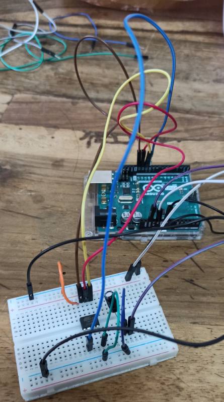
First of all, we tested some circuits to understand how it's work with an Attiny and Arduino. We followed the circuit model presented by Emma Pareschi in her tutorial. Then we tested it with the matrix.
 Slide 15
ATtiny
Materials:
- 5 crocodiles clips
- 5 male male jumpers
- 1 arduino UNO
- 1 USB cable
- 1 Attinyv85
- 1 Electrolytic Capacitor
Software
- Arduino
- Processing
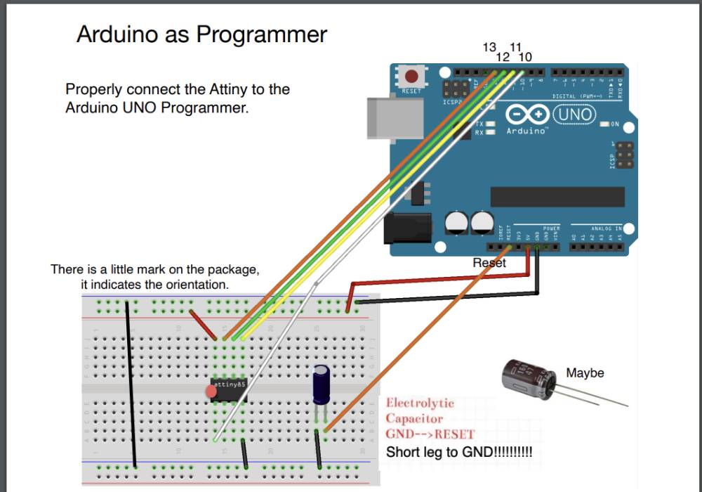
Before testing with the Attiny, it's necessary to prepare the Arduino for being the programmer.
We followed the link of Instructables Website to program the Arduino.
Steps to program Arduino as a programmer
1. Connect the Attiny to you programmer (if it's an Arduino UNO, make sure it's uploaded with the ArduinoISP sketch).
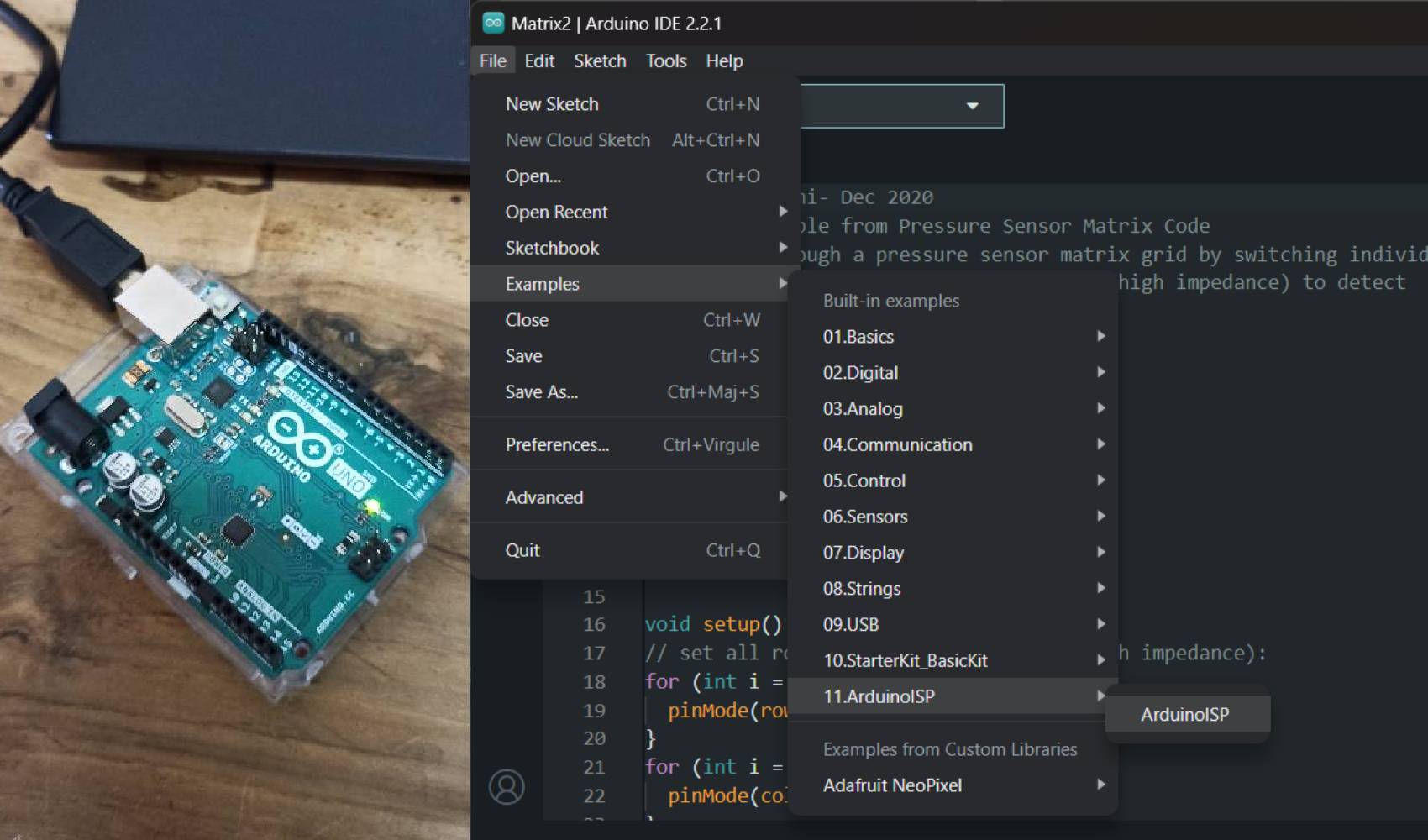
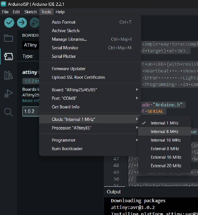
2. In Arduino IDE: Select the board, or upload it (attiny85, clock:internal8MHZ) and port.
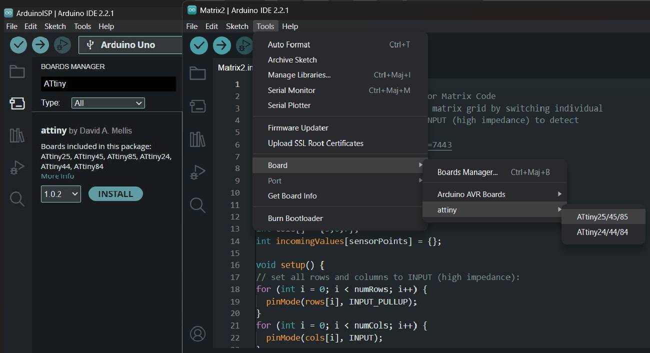
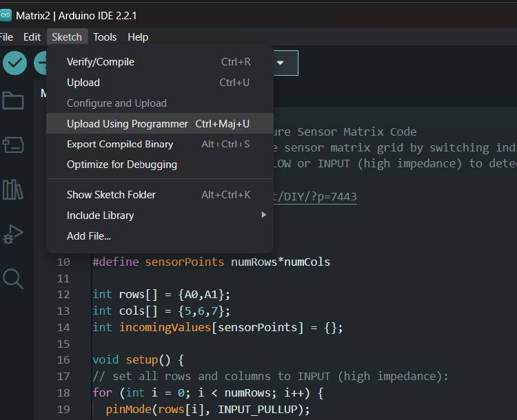
3. In Arduino IDE: select programmer (Arduino as ISP) or choose to upload using programmer. Thats' what I needed to do, because I have an other version (Arduino 2.2.1) than Diane or Amandine.
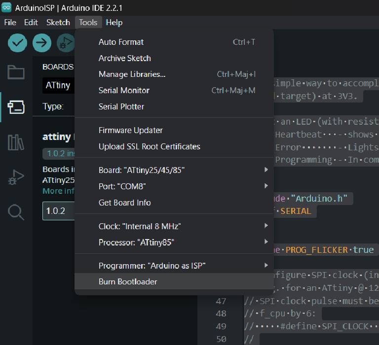
4. If it's the first time using the Attiny, It's necessary to "Burn the bootloader".
5. On Breadboard: connect the Attiny to your input/output devices.
6. In Arduino IDE: upload the code to the Attiny.
Code example
/*Emma Pareschi - Fabricademy 2023
* I turn on a led and I turn it off
* The Led is connected to pin 3
*/

int led_pin = 3; //define the pin where the Led is connected

void setup() {
  pinMode(led_pin, OUTPUT); //define pin of the Led as an output
  //pinMode(pin, OUTPUT);

  //pinMode(pin, INPUT);
  //pinMode(pin, INPUT_PULLUP);
}

void loop() {
//turn the Led on
  //analogWrite(pin, 0/255);d
  digitalWrite(led_pin, HIGH);
  delay(500);
  digitalWrite(led_pin, LOW);
  delay(500);
}
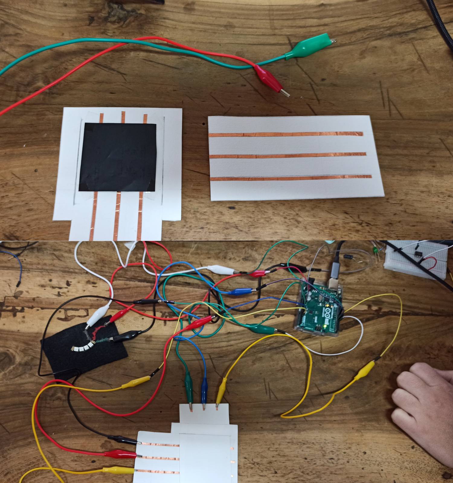
Matrix
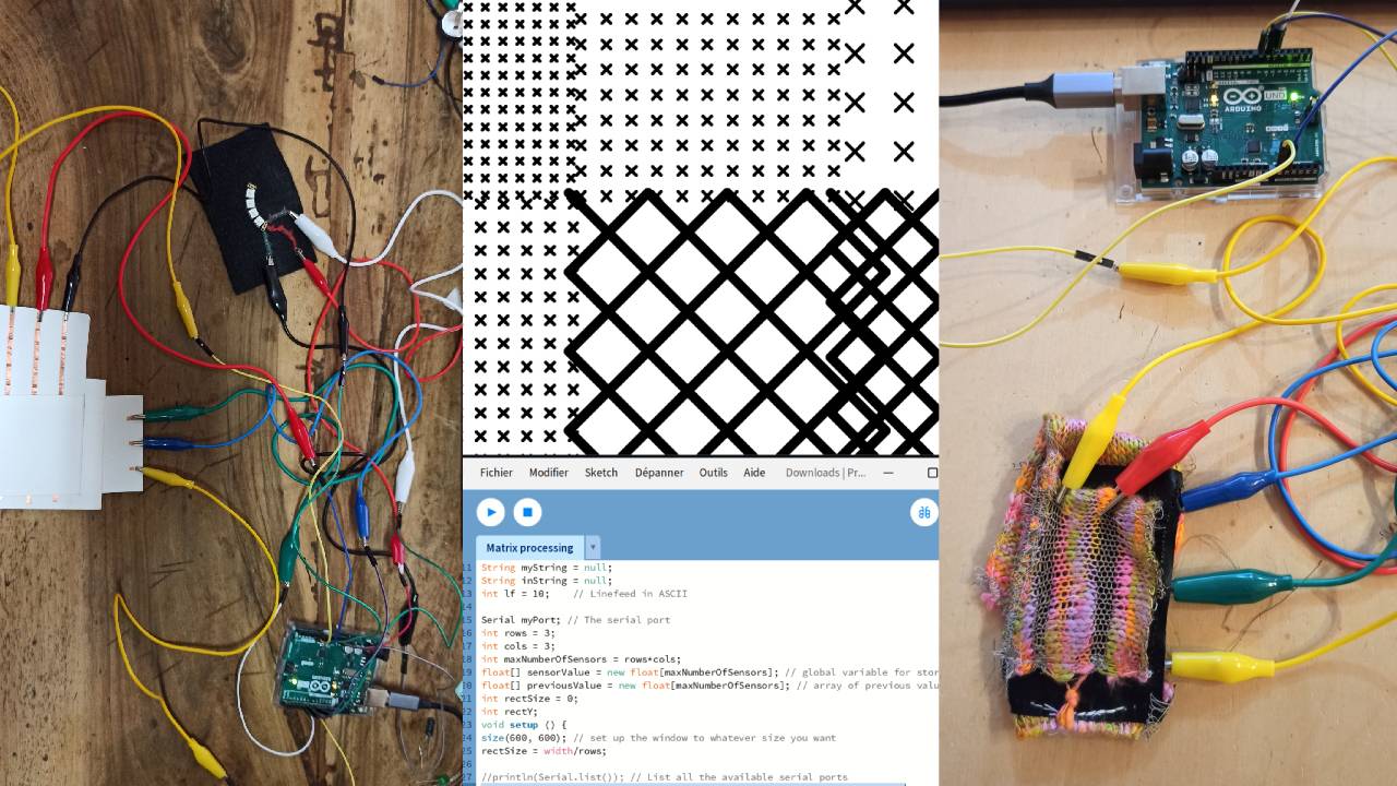
Then we tested the matrix with a piezoresistive pressure sensor, the 3x3 paper matrix made with paper, copper tape and velostat.
Material:
- 6 crocodiles clips
- 6 male male jumpers
- 1 arduino UNO
- 1 USB cable
- 1 3x3 paper matrix
Software
- Arduino
- Processing
Code example with Arduino
//Emma Pareschi- Dec 2020
//Modify example from Pressure Sensor Matrix Code
//parsing through a pressure sensor matrix grid by switching individual
//rows/columns to be HIGH, LOW or INPUT (high impedance) to detect
//location and pressure.
//>> https://www.kobakant.at/DIY/?p=7443

#define numRows 3
#define numCols 2
#define sensorPoints numRows*numCols

int rows[] = {A0, A1};
int cols[] = {5,6,7};
int incomingValues[sensorPoints] = {};

void setup() {
  // set all rows and columns to INPUT (high impedance):
  for (int i = 0; i < numRows; i++) {
    pinMode(rows[i], INPUT_PULLUP);
  }
  for (int i = 0; i < numCols; i++) {
    pinMode(cols[i], INPUT);
  }
  Serial.begin(9600);
}

void loop() {

  for (int colCount = 0; colCount < numCols; colCount++) {
    pinMode(cols[colCount], OUTPUT); // set as OUTPUT
    digitalWrite(cols[colCount], LOW); // set LOW

    for (int rowCount = 0; rowCount < numRows; rowCount++) {
      incomingValues[colCount * numRows + rowCount] = analogRead(rows[rowCount]); // read INPUT
    }// end rowCount

    pinMode(cols[colCount], INPUT); // set back to INPUT!

  }// end colCount

  // Print the incoming values of the grid:
  for (int i = 0; i < sensorPoints; i++) {

    Serial.print(incomingValues[i]);
    if (i < (sensorPoints-1)) {
      Serial.print("\t");
    }
  }

  Serial.println();
  delay(10);
}
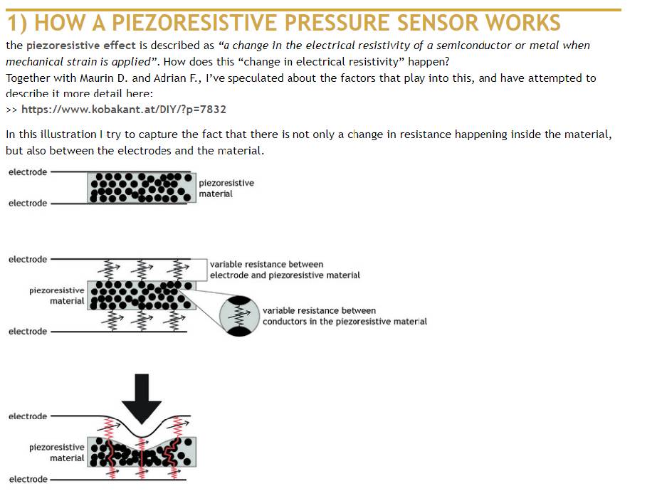
Explanations of how piezoresistive sensor works, Screenshot form Kobakant website
Skin Electronics project
The main idea is to reuse the pattern machine that I created during my week 10.
Creating patterns by interactions with the body matrix using a piezoresistive material like Velostat. Diane also tells us about Jessica Stanley's assignments of this week.
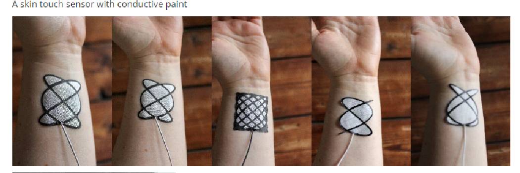
Screenshot form Jessica Stanley's assignments
And we found more inspirations with the Kobakant project: Pressure Matrix code + circuit and the Stretchy touchpad
Process
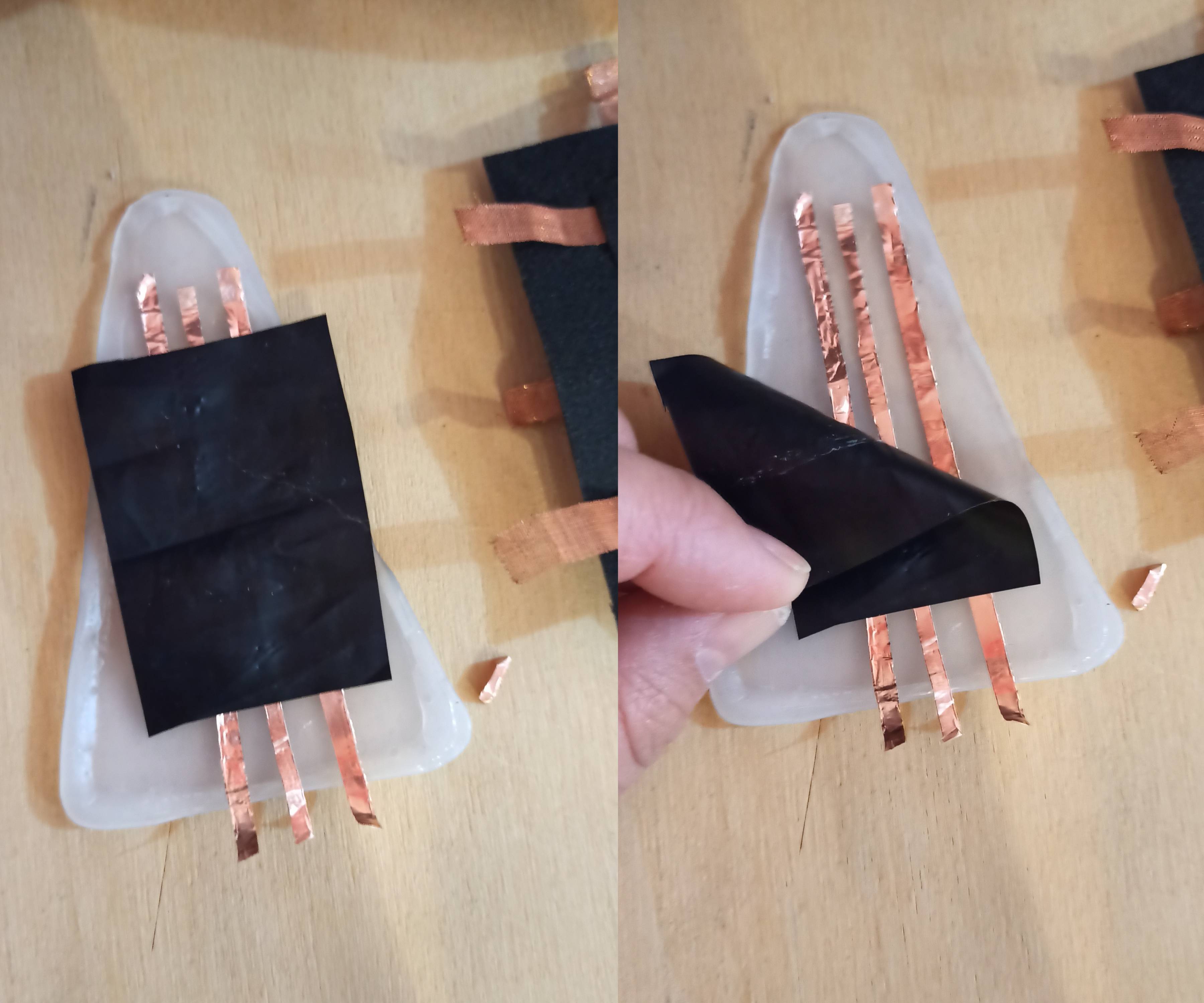
First, we wanted to test it with pieces of silicone left over from my week 9 failed tests, with the idea that it would adhere better to the skin, in a 3x3 version.
But we realized that the copper tape didn't hold despite the glue. The velostat didn't connect properly when pressed between the two layers of silicone.
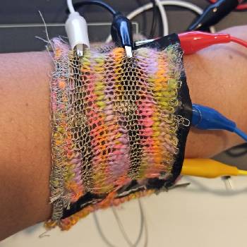
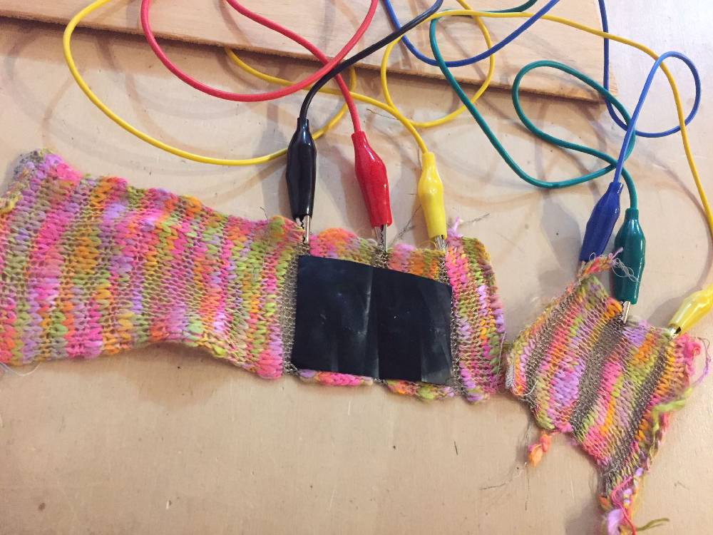
Then, we did a test to knit a bracelet with connected yarn, like the paper matrix. Amandine (who specializes in knitting machines) showed me how to use the kniterate available at Le Textile Lab. It was great fun to try out this machine, as I'm more used to hand-knitting.
The Knitting machine
The use of this machine is not in the objectives of the week. I will add detailed explanations if necessary next time.You can find more explanations on how to use the Brother KH950 via Textile Lab Resources.
Material:
- Conductive thread
- Velostat
- Knitting machine yarn
- Brother KH950
Piece 1
21 stitches in stockinette
40 rows in Tension 5 normal color thread
4 rows in Tension 2 conductive thread
6 rows in Tension 5 normal color thread
4 rows in Tension 2 conductive thread
6 in Tension 5 normal color thread
4 rows in Tension 2 conductive thread
Piece 2
4 rows in Tension 2, conductive thread
6 in Tension 5 normal color thread
4 rows in Tension 2 conductive thread
6 in Tension 5 normal color thread
4 rows in Tension 2 conductive thread
Knitting test
On the left: Piece 1, on the right: Piece 2
Generative patterns and Processing
There was a small error with the serger when I tried to sew the two pieces together. One of the lines knitted with the conductive thread was cut.😓
We modified our code by notifying the number of rows: only 2 instead of 3.
Circle Code example
This is the first code we used to having circles1.
//Emma Pareschi- Dec 2020
//Modify example from Pressure Sensor Matrix Code
//parsing through a pressure sensor matrix grid by switching individual
//rows/columns to be HIGH, LOW or INPUT (high impedance) to detect
//location and pressure.
//>> https://www.kobakant.at/DIY/?p=7443

#define numRows 2
#define numCols 3
#define sensorPoints numRows*numCols

int rows[] = {A0, A1};
int cols[] = {5,6,7};
int incomingValues[sensorPoints] = {};

void setup() {
  // set all rows and columns to INPUT (high impedance):
  for (int i = 0; i < numRows; i++) {
    pinMode(rows[i], INPUT_PULLUP);
  }
  for (int i = 0; i < numCols; i++) {
    pinMode(cols[i], INPUT);
  }
  Serial.begin(9600);
}

void loop() {

  for (int colCount = 0; colCount < numCols; colCount++) {
    pinMode(cols[colCount], OUTPUT); // set as OUTPUT
    digitalWrite(cols[colCount], LOW); // set LOW

    for (int rowCount = 0; rowCount < numRows; rowCount++) {
      incomingValues[colCount * numRows + rowCount] = analogRead(rows[rowCount]); // read INPUT
    }// end rowCount

    pinMode(cols[colCount], INPUT); // set back to INPUT!

  }// end colCount

  // Print the incoming values of the grid:
  for (int i = 0; i < sensorPoints; i++) {

    Serial.print(incomingValues[i]);
    if (i < (sensorPoints-1)) {
      Serial.print("\t");
    }
  }


  Serial.println();
  delay(10);
}
Result
The circle pattern
Ellipse and cross code example
We also tested to have cross and ellipse at the same time.
/*
Code based on Tom Igoe’s Serial Graphing Sketch

> http://wiki.processing.org/w/Tom_Igoe_Interview
Reads X analog inputs and visualizes them by drawing a grid
using grayscale shading of each square to represent sensor value.
http://howtogetwhatyouwant.at/
Working with a matrix
*/

String myString = null;
String inString = null;
int lf = 10;    // Linefeed in ASCII

Serial myPort; // The serial port
int rows = 2;
int cols = 3;
int maxNumberOfSensors = rows*cols;
float[] sensorValue = new float[maxNumberOfSensors]; // global variable for storing mapped sensor values,
float[] previousValue = new float[maxNumberOfSensors]; // array of previous values
int ellipseSize = 0;
int ellipseX;
void setup () {
  size(800, 800); // set up the window to whatever size you want
  ellipseSize = width/rows;

//println(Serial.list()); // List all the available serial ports
  String portName = Serial.list()[0]; // set the number of your serial port!
  myPort = new Serial(this, portName, 9600);
  myPort.clear();
  myPort.bufferUntil('\n'); // don’t generate a serialEvent() until you get a newline (\n) byte
  background(0, 0, 255); // set inital background
  smooth(); // turn on antialiasing
  ellipseMode(CENTER); //define the position of the ellipse from its center
  //ellipseMode(CORNER); //define the position of the ellipse from its corner
}

void draw () {
  background(255);
  for (int i = 0; i < maxNumberOfSensors; i++) {
    fill(sensorValue[i]-28, sensorValue[i]-28, sensorValue[i]-28); //Define first colour of the ellipse
    ellipse(ellipseX + ellipseSize/2, ellipseSize*(i%rows)+ellipseSize/2, ellipseSize*sensorValue[i]/255, ellipseSize*sensorValue[i]/255);
    push();
    translate(ellipseX + ellipseSize/2, ellipseSize*(i%rows)+ellipseSize/2);
    float d = ellipseSize*(1-sensorValue[i]/255)/2;
    line(-d, -d, d, d);
    line(d, -d, -d, d);
    pop();
    if ((i+1) % rows == 0) ellipseX += ellipseSize;
  }
  ellipseX=0;
}

void serialEvent (Serial myPort) {
  inString = myPort.readStringUntil(lf); // get the ASCII string
  println("test");
  if (inString != null) { // if it’s not empty
    inString = trim(inString); // trim off any whitespace
    int incomingValues[] = int(split(inString, "\t")); // convert to an array of ints

    if (incomingValues.length <= maxNumberOfSensors && incomingValues.length > 0) {
      for (int i = 0; i < incomingValues.length; i++) {
        // map the incoming values (0 to 1023) to an appropriate gray-scale range (0-255):
        sensorValue[i] = map(incomingValues[i], 0, 1023, 0, 255); // stretch 5×5, because sensor value = 255 at rest (without pressure)
        //incomingValue decreases with pressure because it is the resistance
        sensorValue[i] = constrain(incomingValues[i], 0, 255); // stretch 5×5
        println(sensorValue[i]); // print value to see
      }
    }

  }
}
Result
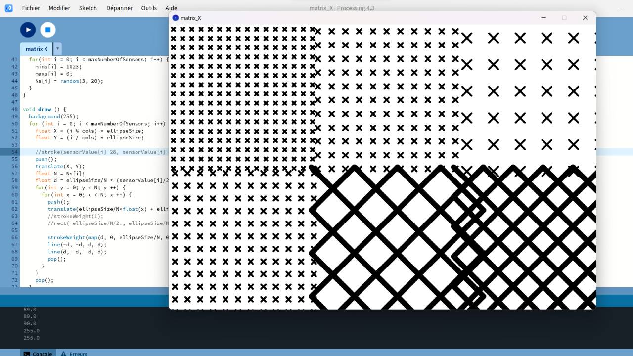
Cross code example
As we also wanted to try and generate a pattern with different cross sizes in each square, I reviewed the Processing code with the help of my husband (The Processing guy!)2.
/*
Code based on Tom Igoe’s Serial Graphing Sketch

http://wiki.processing.org/w/Tom_Igoe_Interview
Reads X analog inputs and visualizes them by drawing a grid
using grayscale shading of each square to represent sensor value.
http://howtogetwhatyouwant.at/
Working with a matrix
*/

String myString = null;
String inString = null;
int lf = 10;    // Linefeed in ASCII

Serial myPort; // The serial port
int rows = 2;
int cols = 3;
int maxNumberOfSensors = rows*cols;
float[] sensorValue = new float[maxNumberOfSensors]; // global variable for storing mapped sensor values,
float[] previousValue = new float[maxNumberOfSensors]; // array of previous values
int[] mins = new int[maxNumberOfSensors];
int[] maxs = new int[maxNumberOfSensors];
float[] Ns = new float[maxNumberOfSensors];

float ellipseSize = 0;

void setup () {
  size(1200, 800); // set up the window to whatever size you want
  ellipseSize = float(width)/float(cols);

  //println(Serial.list()); // List all the available serial ports
  String portName = Serial.list()[0]; // set the number of your serial port!
  myPort = new Serial(this, portName, 9600);
  myPort.clear();
  myPort.bufferUntil('\n'); // don’t generate a serialEvent() until you get a newline (\n) byte
  background(0, 0, 255); // set inital background
  smooth(); // turn on antialiasing

  for(int i = 0; i < maxNumberOfSensors; i++) {
    mins[i] = 1023;
    maxs[i] = 0;
    Ns[i] = random(3, 20);
  }
}

void draw () {
  background(255);
  for (int i = 0; i < maxNumberOfSensors; i++) {
    float X = (i % cols) * ellipseSize;
    float Y = (i / cols) * ellipseSize;

    //stroke(sensorValue[i]-28, sensorValue[i]-28, sensorValue[i]-28); //Define first colour of the ellipse
    push();
    translate(X, Y);
    float N = Ns[i];
    float d = ellipseSize/N * (sensorValue[i]/255.)/2.;
    for(int y = 0; y < N; y ++) {
      for(int x = 0; x < N; x ++) {
        push();
        translate(ellipseSize/Nfloat(x) + ellipseSize/2./N, ellipseSize/Nfloat(y) + ellipseSize/2./N);
        //strokeWeight(1);
        //rect(-ellipseSize/N/2.,-ellipseSize/N/2., ellipseSize/N, ellipseSize/N);

        strokeWeight(map(d, 0, ellipseSize/N, 0, 30));
        line(-d, -d, d, d);
        line(d, -d, -d, d);
        pop();
      }
    }
    pop();
  }
}

void serialEvent (Serial myPort) {
  inString = myPort.readStringUntil(lf); // get the ASCII string
  //println("test");
  if (inString != null) { // if it’s not empty
    inString = trim(inString); // trim off any whitespace
    int incomingValues[] = int(split(inString, "\t")); // convert to an array of ints

    if (incomingValues.length <= maxNumberOfSensors && incomingValues.length > 0) {
      for (int i = 0; i < incomingValues.length; i++) {
        // map the incoming values (0 to 1023) to an appropriate gray-scale range (0-255):
        if(incomingValues[i] > maxs[i]) maxs[i] = incomingValues[i];
        if(incomingValues[i] < mins[i]) mins[i] = incomingValues[i];

        sensorValue[i] = map(incomingValues[i], mins[i], maxs[i], 0, 255); // stretch 5×5, because sensor value = 255 at rest (without pressure)
        //incomingValue decreases with pressure because it is the resistance
        sensorValue[i] = constrain(incomingValues[i], 0, 255); // stretch 5×5
        println(sensorValue[i]); // print value to see
      }
    }
  }
}
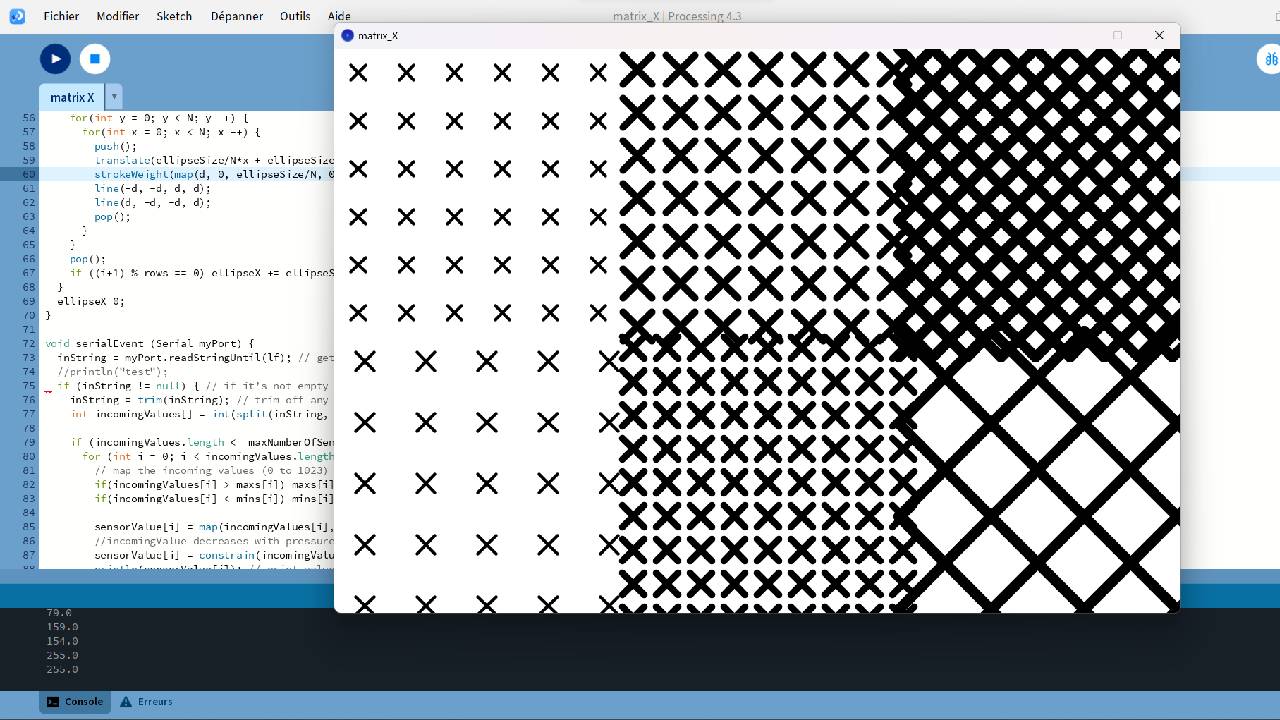
Result
But there seems to be a problem, perhaps in my code or in the formatting of the two knitting pieces. The starting grid already has patterns, whereas these should appear when the two fibers make contact with the velostat when it's pressed.
Final Result
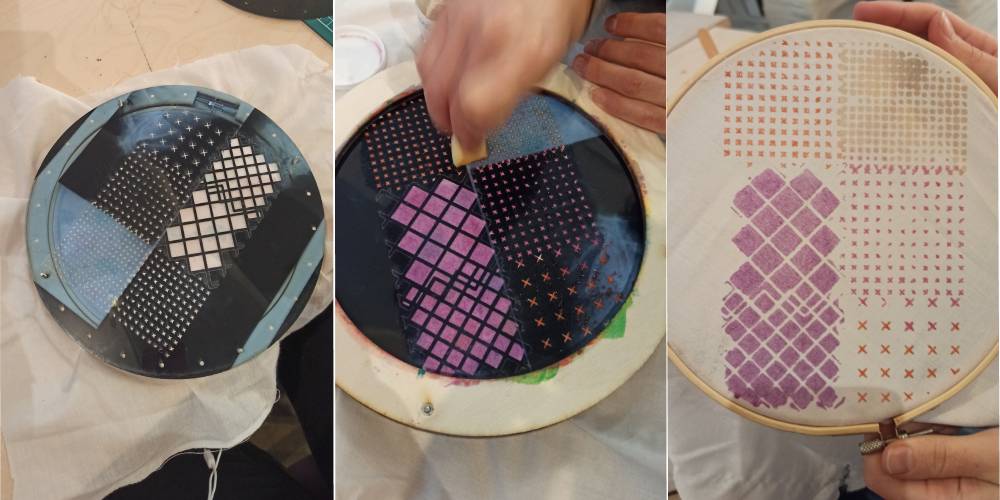
We chose to test one of the patterns generated by the bracelet with the cut-out.
Amandine experimented with vectorizing with Illustrator the resulting images before launching them on the laser cutter.
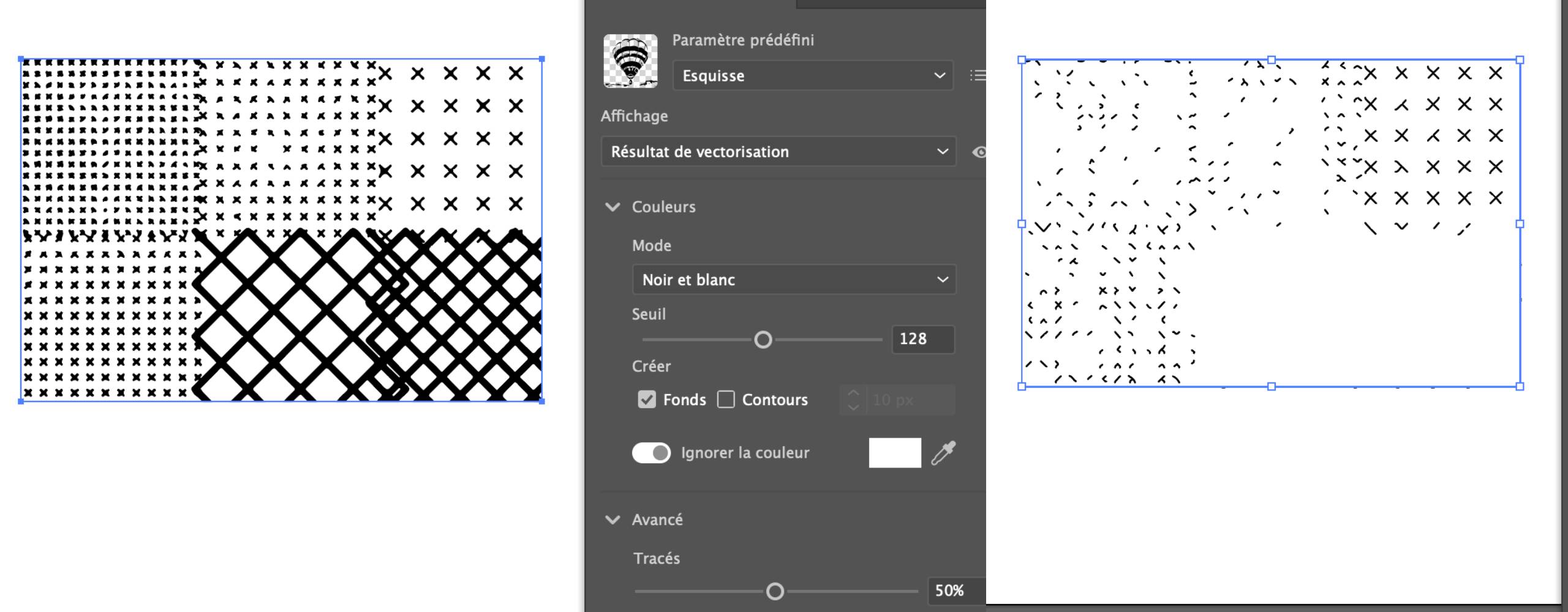
Not all of the cut results could be used with the pattern machine. We tried the one with the "best" cut with printing pastes that I made for week 10.
🚀 Going further
To take this a step further, the idea would be to generate new ones and to rework the visuals of the patterns obtained with the die so that they can be cut without error by the laser cutter and printed with the pattern machine or just on paper.
Or make a prototype using the Kobakant model directly on the skin in an electronic tatoo version.
And to take up one of the ideas of electronic tattooing, I would also like to try Emma Picanyol's project for this week.
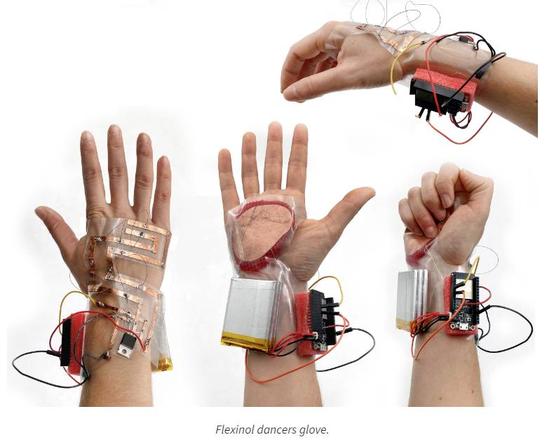
Screenshot of Emma Picanyol's flexinol dancers glove