5. E-textiles
This week I had a loooot of fun!:D Mainly because I love stitching and embroidery and I enjoy experimenting with new materials and being quite hands on as opposed to being on my laptop all the time. I would say that this week was really exciting because this was something totally new for me!
This week was loaded with new information- from how electrons move, basic electronics, to talking about conductive and resistive soft materials, to soft and hard connections, to arduino and programming.
This week's assignment in simple words:
To create a digital and an analog sensor and intergrate them into swatches and arduino!
Learning outcomes
-
Understand how we can produce soft circuits, sensors and actuators
-
Learn how to embed them in garments, soft objects or wearables
-
Study and learn soft-hard connections
-
Discover necessary materials, components, tools
-
Explore and replicate existing projects
Research and Inspiration
I literally know nothing about the practical making of wearables and e textiles but I have been researching and looking into particular projects for a while now, however, it is a brand new world for me :) Down below you can find a collage of projects from the lectures and from my own research that inspired me! I am also interested in combinining biofabricated materials, biochromes and electronics somehow. We will see how that goes in the next few months.

Lectures Highlights
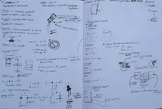
Some of my doodles and notes from the lectures
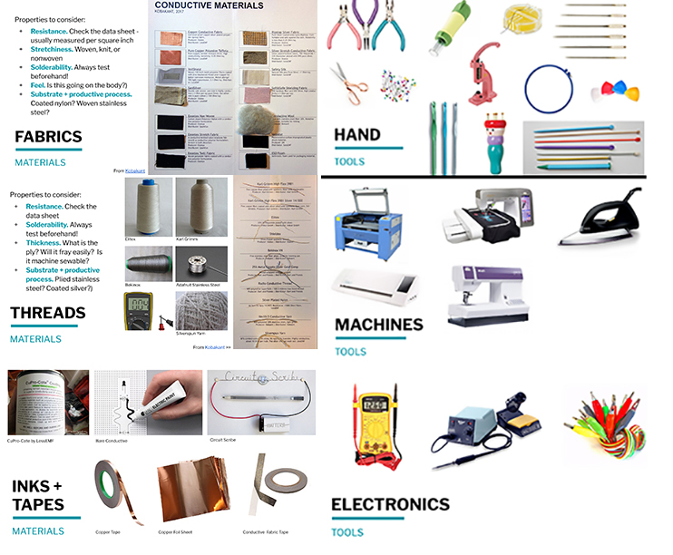
Meet your new materials and tools! Images from Liza Stark's lecture @fabricademy
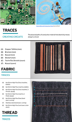
Traces
Traces are the physical paths of conductive material in which electricity can flow through in a circuit! In making e-textiles these can be different conductive fabrics, tape, ink and threads.
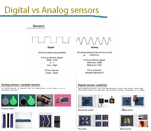
Digital vs Analog
Digital sensor and swatch-Fabric Button
My digital switch is not exactly identical as the fabric button but it follows this principle with putting a cut piece of foam in the middle and conductive fabric in the middle so whenever we press it and the 2 conductive parts are in conduct we have a switch! Found at Kobakant.at.
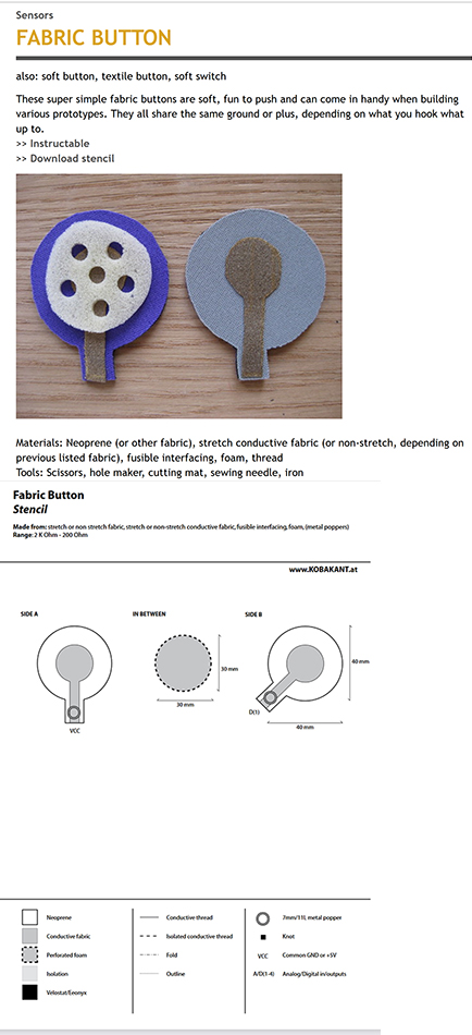
Images from Kobakant.at on how to make your own fabric button switch
The making of the sensor and the swatch
In the beggining I made a really quick and dirty example of a digital switch and I wanted to see if it works! For this quick tests you can use materials such as:
-
Putting my first quick and dirty digital switch into the test by intergrating it into a circuit using conductive thread, an LED light, a 3V battery, and some crocodile wires
Digital sensor swatch
A very rough schematic of the swatch and how the digital switch is incorporated in the circuit
The making of the digital sensor and the swatch
Gif video of the finished digital swatch and how it works
Analog Sensors- the making of
Bend Sensor
You can find the stencil of Neoprene bend sensor along with instructions and updates here.
Bill of materials, tools and other instructions
-Materials: Neoprene, conductive thread, stretch conductive fabric, Velostat, fusible

-Tools: Fabric scissors, fabric pen, stencil, sewing needle, iron, pliers
Instructions
-Trace the stencil (found on the website above)

-After cutting out the neoprene pieces, trace the stencil to them. Fuse tabs of conductive fabric to either end.

-Sew with conductive thread

-Thread a needle with conductive thread and stitch along the stencil pattern until you reach the tab of conductive fabric. Stitch the conductive thread to the conductive fabric with a few stitches to make good contact. Repeat for both sides.


-Layer the neoprene with the conductive traces inwards so that the stitches criss-cross. The Velostat goes in between.

-Sew the sensor together around the edges making sure not to sew too tight.

-To make sure your bend sensor is working. Connect either end to a multimeter and set to measure resistance (ohm). Your initial resistance should lie around 2K ohm and should sink to about 100 ohm when pressured by pushing down hard.

-Attaching to the body: When attaching the sensor to the body one has to pay attention not to create too high initial pressure. Otherwise the sensor’s range is useless. We like to use metal poppers to connect the sensors to the rest of the wearable circuit.
I only used 1 piece of neoprene because I wanted my sensor to look different from each side.Instead have put only neoprene on one side of my sensor and on the other side I decided to double up a cotton patterned fabric which I joined by stitching. In this way I created a hidden pathway for my conductive thread trace so only one side has contact with the respective path on the opposite piece (neoprene piece). Because neoprene is thicker and has more internal volume lets say than the cotton I followed the stencil instructions from Kobakant.at.
A little show off of the constructed bend sensor
Stroke Sensor/s
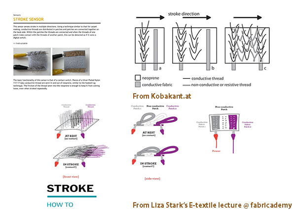
Instructions for making one of the stroke sensors from Kobakant.at and from Liza Stark's E-textile lecture @ fabricademy
Little show off of the sensor. If i was to change something about it it would be the length of the threads. I will explain why down below :)
Bill of materials
-Neoprene fabric as a base
-Conductive thread
-Conductive fabric
-Other threads (non conductive)
-I did not use any machines again. Just a needle and some glue for the conductive fabric at the back!
As the contact of the conductive threads acts as a switch, the long conductive threads were in a lot of contact with each other and the resistance was low. I will shorten my threads next time!
Aaaand some photos of some of the sensors I made during this week
ARDUINO UNO
Intergrating the digital sensor in Arduino UNO
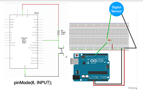
Schematic diagram from Emma Pareschi's lecture
Reading the values of my digital sensor in the serial monitor with the _read_DigitalSensor sketch
Code for 03_read_DigitalSensor
*we read the value of a digital sensor connected to pin digital_sensor_pin and
*we print it on the Serial Monitor
*/

int digital_sensor_pin = 8;     //change the pin, where the sensor is connected?
int digital_sensor_value = 0;

void setup() {
// put your setup code here, to run once:
pinMode(digital_sensor_pin, INPUT); //define the pin as INPUT
Serial.begin(9600);

}

void loop() {
// put your main code here, to run repeatedly:
digital_sensor_value = digitalRead(digital_sensor_pin); // read the sensor

Serial.println(digital_sensor_value); //print the value
delay(100);

}
Here I have added an LED to the previous circuit and I am controlling it with my digital densor
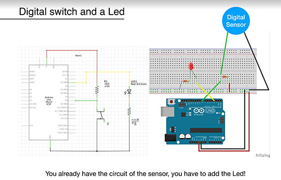
Schematic of the circuit
Here we are using the Button led sketch! I have added the code below!
Button_led code
*this sketch is a modification of the example button!!
*/

int digital_sensor_pin = 7;     //change the pin, where the sensor is connected?
int digital_sensor_value = 0;
int led_pin = 3; //change the pin of the Led

void setup() {
// put your setup code here, to run once:
pinMode(digital_sensor_pin, INPUT);
Serial.begin(9600);
// initialize digital pin LED_BUILTIN as an output.
pinMode(led_pin, OUTPUT);

}

void loop() {
// put your main code here, to run repeatedly:
digital_sensor_value = digitalRead(digital_sensor_pin);

// check if the pushbutton is pressed. If it is, the buttonState is HIGH:
if(digital_sensor_value == HIGH){
        // turn LED on:
    digitalWrite(led_pin, HIGH);
} else {
        // turn LED off:
    digitalWrite(led_pin, LOW);    // turn the LED off by making the voltage LOW

}

}
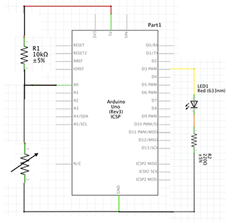
Intergrating my analog sensors to Arduino Uno
The analog sensor is a variable resistor!!To read an Analog sensor that generates an analog voltage you need to use the ANALOG PINS (A0-A5 on the Arduino Uno board).
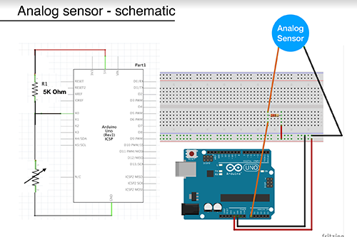
Analog sensor schematic
Just like with the digital sensor you can also read and map an analog sensor with _read_AnalogSensor_map funtion! The code for this is down below.
_read_AnalogSensor_map code
*with this sketch we read the analog sensor connected to pin analog_sensor_pin
*/

int analog_sensor_pin = A0;   //change the pin, where the sensor is connected?
int analog_sensor_value = 0;

void setup() {
// put your setup code here, to run once:
pinMode(analog_sensor_pin, INPUT);
Serial.begin(9600);

}

void loop() {
// put your main code here, to run repeatedly:
analog_sensor_value = analogRead(analog_sensor_pin); //read the Voltage of the pin sensor

analog_sensor_value = map(analog_sensor_value, 230, 130, 0, 255); //we change the range
analog_sensor_value = constrain(analog_sensor_value, 0, 255); //we apply the limits

Serial.println(analog_sensor_value); // print the value on the Serial monitor
delay(100);

}
You will notice how big the value interval is and then the next step is to Smooth those values and optimise them so you can control an OUTPUT afterwards when you want to incorporate your analog sensor in a swatch, in a wearable etc.
Smoothing
For that you will go to Example -> Analog -> Smoothing and then Open Tools -> Serial Plotter and you will see how much smooth is the signal of the sensor.
Analog sensor and a led- Read and print the value of an Analog Sensor connected to Arduino
The schematic drawing of the analog sensor paired with a led this time as our OUTPUT

Schematic drawing of the arduino circuit of the analog sensor with a led
After we map the values of the sensor then we use these values to control the led, our OUTPUT in this case. We can do that by using the 07_pressure_led sketch. You can find the code below.
07_pressure_led sketch code
*with this sketch we read the analog sensor connected to pin analog_sensor_pin,
*we map the value and we use it to control the Led
*/

int analog_sensor_pin = A0;   //change the pin, where the sensor is connected?
int analog_sensor_value = 0;
int led_pin = 3;


void setup() {
// put your setup code here, to run once:
pinMode(analog_sensor_pin, INPUT);
pinMode(led_pin, OUTPUT);
Serial.begin(9600);
!
}

void loop() {
// put your main code here, to run repeatedly:
analog_sensor_value = analogRead(analog_sensor_pin); //read the Voltage of the pin sensor

analog_sensor_value = map(analog_sensor_value, 230, 130, 0, 255); //we change the range
analog_sensor_value = constrain(analog_sensor_value, 0, 255); //we apply the limits

analogWrite(led_pin, analog_sensor_value);  //we use the mapped value to control the Led
Serial.println(analog_sensor_value); // print the value on the Serial monitor
delay(10);

}
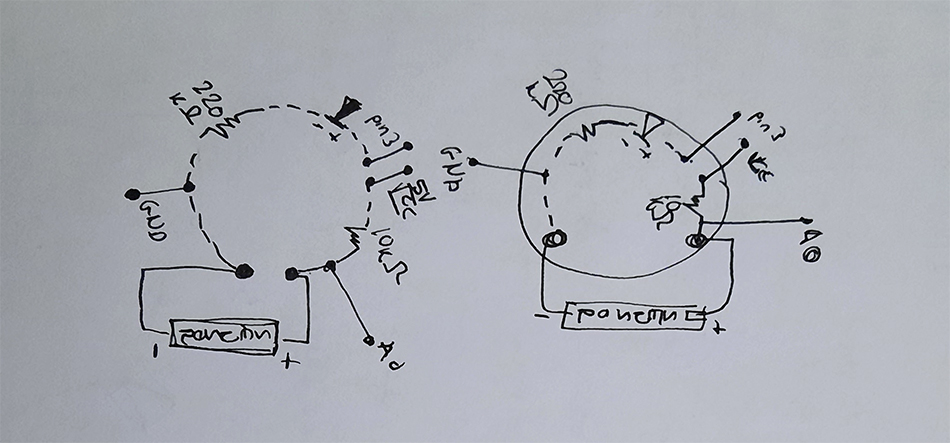
After all the above you can go on and use the same schematic in the top of this subsection and try to translate that into a swatch. It was hard at the beggining but once I followed the schematic it became a lot easier. Here is a rough drawing of my swatch to the sensor and arduino connections!
Ta-dahhh!!! look at the gif below to see the final analog bend sensor swatch.
Intergrating and testing the bend sensor in a swatch
I used the same swatch for both the bend and the stroke sensor even though i did not map the values or did any smoothing to the stroke data. Unfortunately I did not have more time to play with this so I just used the same swatch with the same mapping values.
Intergrating and testing the stroke sensor into the arduino circuit
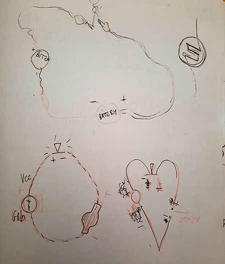
Something for fun- Boob love digital sensor swatch
I wanted to make something for fun and I thought to incorporate my heart shaped digital switch into a swatch with a pair of boobies that light up every time you give them some love aka touch the love button!
aaaand the finished version of the Boob love swatch!
I made this on my free time! I did not use any machines, I cut the felt with scissors and made a digital sensor (The heart) like the one above with foamy material, conductive fabric, and neoprene for the outside.
I used 2 3v batteries, 2 resistance with 220kΩ, 2 led lights, conductive thread, and I sew everything on the base on the embroidery hoop! I will try to find the schemaric of the circuit and add it as soon as possible!
Useful links
- Arduino
- Fabric button, Kobakant
- Stroke sensor, Instructables
- Stroke sensor, Kobakant
- Neoprene bend sensor, Kobakant
- E-textile swatch exchange
- Kobakant