13. Skin Electronics
This week was super fun and something totally new for me again. Katia Vega's lecture for Skin electronics was fascinating and Beauty tech sounds like an amazing field of study and practice.
I tried to start with an ATtiny this week but I was terrified at first. I had some issues with my laptop's usb ports so I could not use the AVR programmer unfortunately so eventually I knew Arduino was my only option to start with and when I feel comfortable I can go from there to the ATtiny just make sure I change the pin numbers on the sketches and transpose from one component to the other. Follow me down below to see what I came up for this week :)
Research and Inspiration
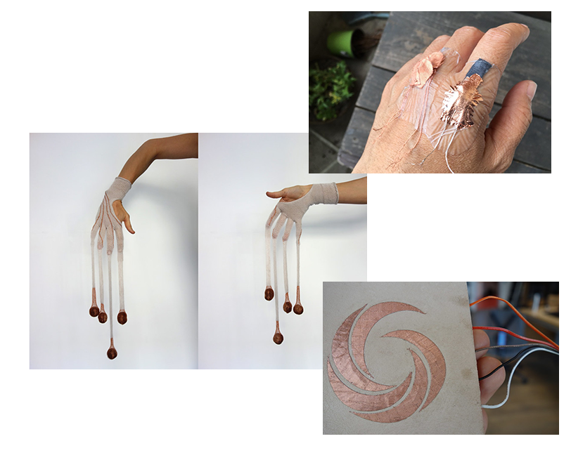
Dangle data gloves, capacitive slider wheel and skin sensor from KOBAKANT
Highlighs from Katia Vegas lecture on Skin electronics and Beauty Tech
Katia's field of research is fascinating! I want to get more into HEALTH and BEAUTY tech! :) Below you can find some images from the lecture and some inspirational works.
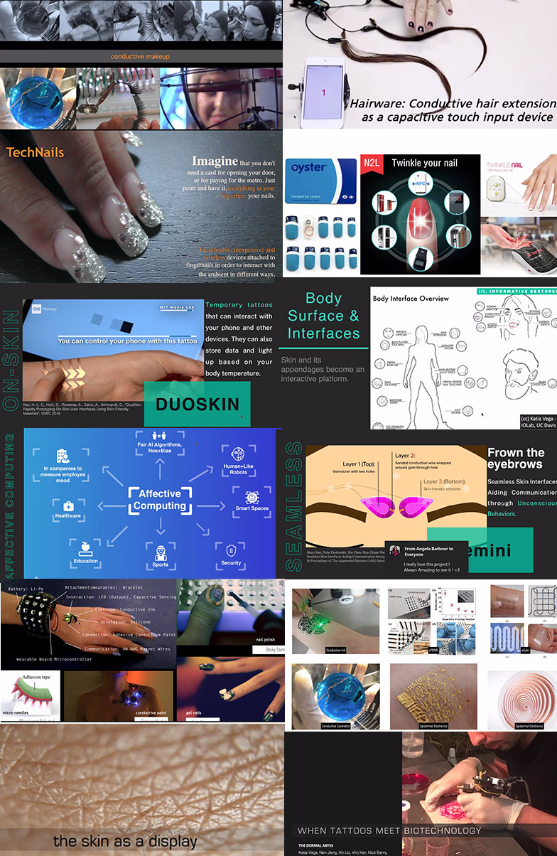
If you are interested in skin electronics check out the lecture by Katia Vega by clicking on the vimeo player below!
This week's experimentations
I wanted to play with capacitive wheel skin sensors and neopixels for my experimentation this week so I followed some instructions from here at KOBAKANT .
I also thought about playing with some PVA glue and thermochromic or conductive paints but those experiments failed! I mixed the electric/conductive paint of Bare Conductive with some PVA glue to see whether I can make something that can go on the skin for a capacitive sensor touch.
Here is a video with the things you can do with the conductive paint!
I also tried to mix that paint with my silicone but AGAIN that piece was not conductive. I did not have time to think so I abandonded that idea with the conductive layers with silicone and PVA. Here are some videos and photos of my fails!
The film i created was not conductive therefore I could not use it. I wanted to use my conductive borax crystals from Textile as scaffold week 9 to make a capacitive sensor but it seems like they are not conductive either!
Also, take a look at this material and tool list just to get an idea on what kind of things you can use for this week's assignment!
| Material | Details |
|---|---|
| Microcontroller | Arduino UNO or ATtiny |
| ATtiny | ATtiny45 or ATtiny85 |
| AVR programmer | or Arduino UNO |
| Arduino kit | Arduino Starter kit |
| Adafruit Gemma | Gemma board |
| FTDI cable | or FTDI board |
| Neopixels sewable | Flora neopixels |
| Capacitor | Capacitor 10uF |
| Threads | resistive/conductive threads |
| Inks | resistive/conductive inks for e-make up |
| RFID tags | +RFID board and shield |
| Craft glue | E600 |
| Liquid latex | for e-make up |
| Gold leaf sheet | for e-make up |
| Thermochromic ink | for e-make up |
| Actuators | Mini vibration motors, speakers… |
| Wires | jumpers, alligator clips wires |
| Tools |
|---|
| Multimeter |
| Soldering iron (Soldering station) |
| Pliers, wire stripper, flush snips, tweezers |
| Vinyl cutter or laser cutter |
| Embroidery / Sewing machine |
| PCB milling machine |
Part I: Lasercutting conductive fabric for capacitive skin sensor/s
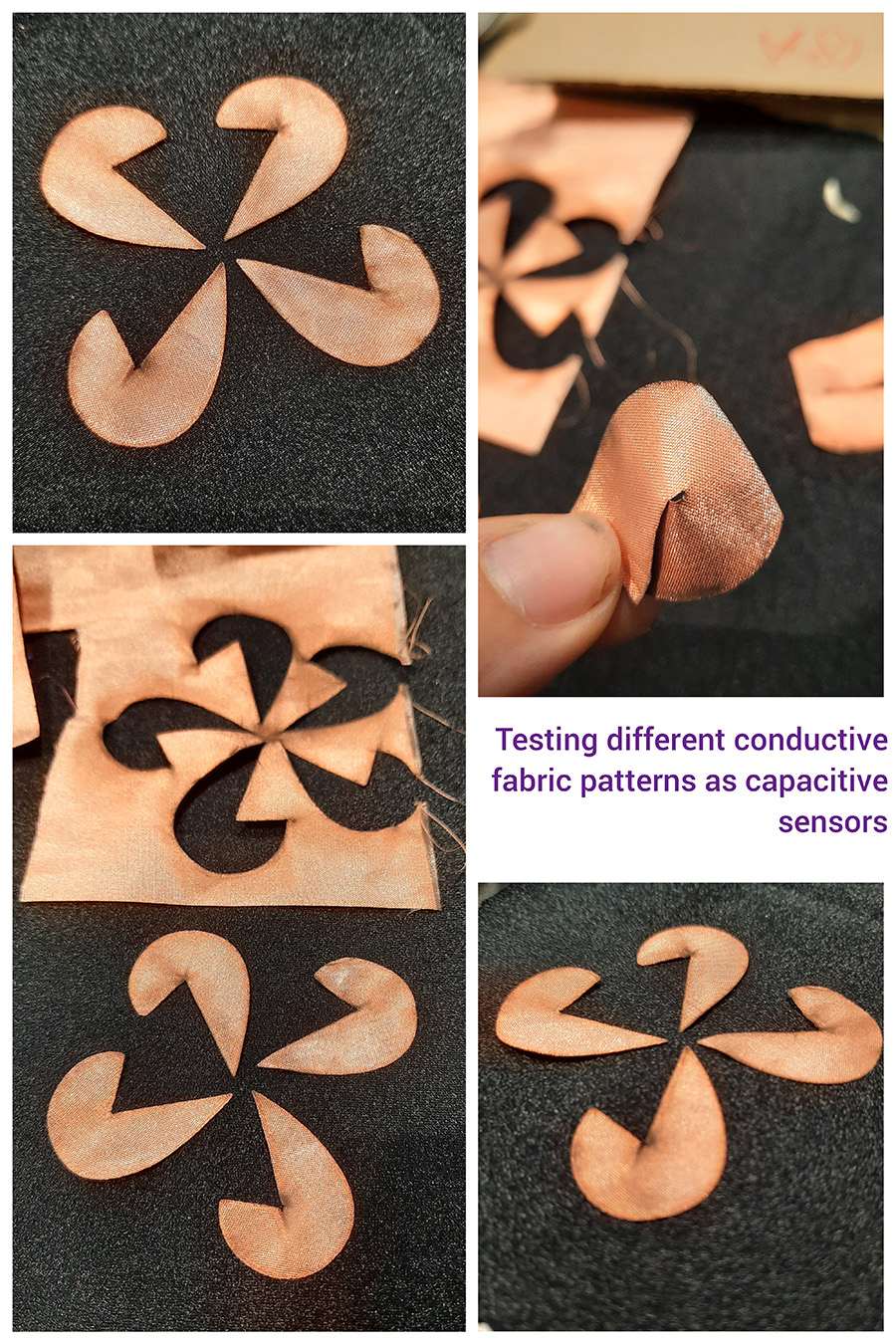
I saw this other fishscale SKIN sensor from the example of KOBAKANT, here and I thought I can play with that too! In the beggining I cut some of the fischscales by had but they were too tiny so then I decided to make a Rhino drawing and cut them with the lasercut.
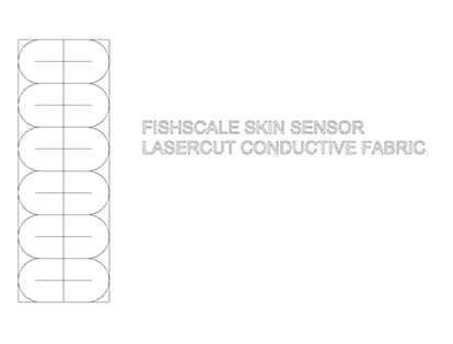
Rhinoceros drawing of the fishscale skin sensor. Unfortunately I did not put the different lines in different layers but Marta, our lasercutter, still got the point and I had an almost OK result
Example from KOBAKANT Skin sensor
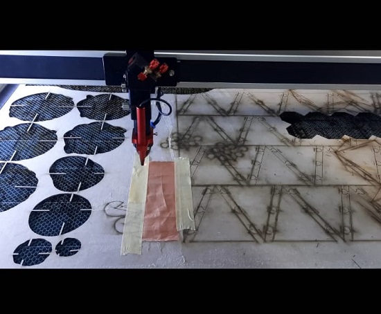
Mounting the conductive fabric on a piece of cardboard with some paper tape in order to lasercut!
 )
)
We used the paper parameters as seen in the photo here
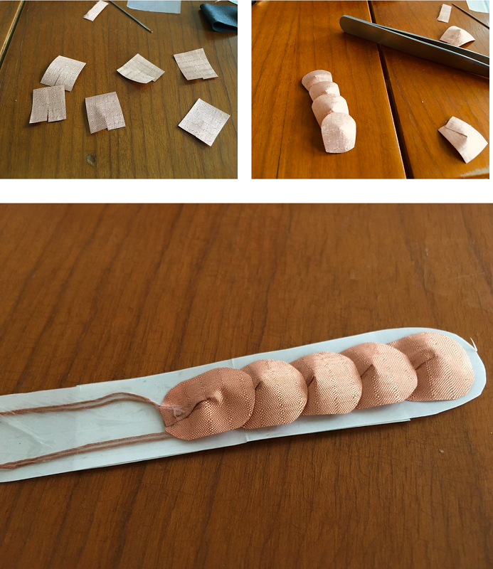
We started the process of lasercutting the fishscale design on conductive copper fabric but then we realised that my drawing was not done properly. I should have done the curves, the middle line and the other lines in different layers but instead I forgot to! Despite the fail, the pieces are still workable and nothing will go to waste.
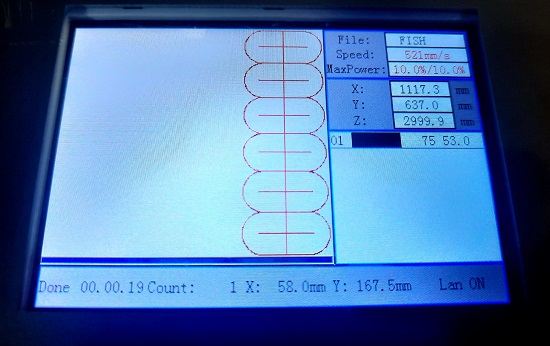
I have been eyeeing this capacitive slider wheel since e-textiles week and now I rediscovered it from Emma's tutorials. I decided to make my own pattern on Rhinoceros and lasercut the conductive fabric. I used the paper parameters, the same as the image above for the fishscales.

Lasercutting a pattern for making a capacitive slider wheel. We should have kept the vacuum off because the pieces were flying about as you can see.
However, a capacitive slider wheel with the neopixel strip needs an arduino to work which means that the outcome will not be suitable for an actual wearable piece because it lacks miniaturisation elements (like the ATtiny). Then I wondered whether and how and if I can translate that to ATtiny. I also wondered how and if i should add resistance when i translate to atiny because on the original example only an arduino and 5 pins are being used with a led strip and no resistance.
This is what Emma advised me to do-
In the kobakant tutorial there are not resistors because the code use a different library for Arduino. I have no exprience with CVDSense Library. Looking at the official library repository https://github.com/admarschoonen/TouchLib, the hardware supported by the library doesn't include the Attiny, it doesn't work on the Attiny. I see some options:
1) you integrate the resistor and you share the sending pin for the different pads. If you look at the example of the library Capacitive Sensor (the one we used), the pin 4 is shared by three sensors. You should be able to have 4 sensors. But you don't have any other pin available for output. 2) you use an extra board, the Adafruit MPR121 12-Key Capacitive Touch Sensor Breakout, https://learn.adafruit.com/adafruit-mpr121-12-key-capacitive-touch-sensor-breakout-tutorial/overview, and in the example code (there is library) you will need to adjust the code for the attiny.
Part II: Capacitive fingertip touch
I had some spare silicone parts from Soft Robotics week so I took those to experiment a bit with sewing neopixels and stuff but then I decided I wanted to combine the fishscale fingertip sensor idea as a switch that will light up a neopixel or just a simple LED with the contact of the fingertips!
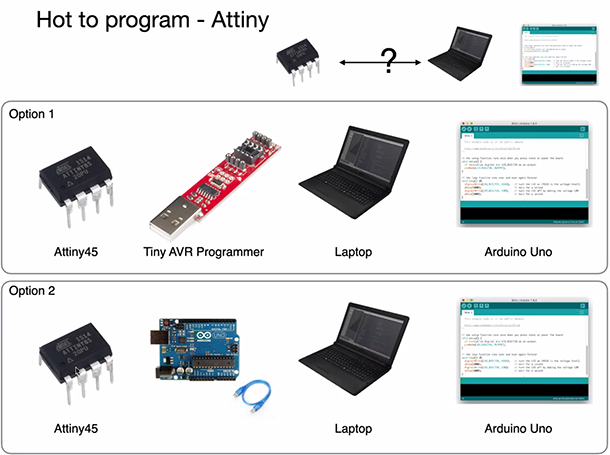
I was not sure whether I can put the conductive fabric directly onto my skin so I thought I should try with a glove first. Buuuut before I design a circuit and get a code for my final result I need to PROGRAM THE ATTINY!! I will provide both ways to program the ATtiny:
- With a Tiny AVR Programmer
The Tiny AVR Programmer plugs directly into your USB port and provides a programming socket for the ATTiny45 and 85. Just slot an ATtiny with a DIP footprint into the socket, plug the programmer into your USB port and start up the Arduino IDE. After installing the proper board definitions, you simply program it the same way you would any other Arduino board. The programmer even breaks out the IC pins to female headers so you can easily prototype around the ATtiny without pulling and plugging it over and over. There are two ISP headers that have also been broken out so you can use the programmer or solder in a 6-pin header for other AVR microcontrollers!
Note: You'll need to install the USBTinyISP drivers if you don't have them yet.
You can download the drivers here
- With an Arduino Uno board
Programming the ATtiny with the tiny AVR Programmer
Here are some basic initial steps in order to start programming with the AVR Programmer!
1. You need first to install the [drivers](https://cdn.sparkfun.com/datasheets/Dev/AVR/usbtinyisp_libusb_1.2.6.0.zip), as posted in the setion above.
2. Select your board (Tools > Board > ATtiny).
3. Select the correct ATtiny (Tools > Processor > ATtiny85).
4. Set the clock timing at 8MHz (Tools > Clock > 8 MHz (internal)). Next click "Burn Bootloader".
5. Select the programmer (Tools > Programmer > USBtinyISP).
6. Open your sketch (in this case the Blink example). Change the pin to 2, then click on Upload. Note: It is OK if the tiny programmer doesn't show up here (Tools > Port > - ).
7. For trying the sketch uploaded before, carefully remove the ATtiny from the mini programmer and put into the circuit shown on a breadboard. The LED should blink.
Programming the ATtiny with an Arduino Uno
Some of Emma's advise on this week's assignment was also that we can-
Use all the codes (and circuits) I shared during wearable weeks but: - Change the pin numbers! - Remove all Serial commands
I had ALL the issues you can possibly imagine with programming the ATtiny. First, it was my usb cable and the connection with the AVR programmer. Then I tried Arduino. Then I changed my cable and the issues are still there. Then I changed to another Arduino and still, does not work!
I also tried with a new ATtiny because I noticed that I ruined one of the legs from trying too much, haha. I got a new ATtiny and used another computer, but still nothing.
Sewing the final circuit onto my material for some fingertip capacitive touch sensing!
I have sewn my circuit on spare a piece of bacterial cellulose I had but I made sure that I doubled the surface to i can sandwich and sew my circuit in layers so I don't put it directly onto my skin. Since I had so many issues with my mini usb ports on my computer I decided to do something simple for this assignment.
Useful links
- Textile as Scaffold, conductive borax crystals
- KOBAKANT, capacitive slider wheel
- KOBAKANT, DANGLE DATA GLOVES
- KOBAKANT, Skin Sensor
- Tiny AVR PROGRAMMER, SPARKFUN
- Bare Conductive