5. E-textiles
TERMINOLOGY FOR THIS WEEK :
Circuit - A path for electricity to flow. Electric flow is the movement of electrons which always go from the positive pole to the negative pole (from the most loaded side to the less loaded side). There are two different types of circuits : parallel or series. Objects that are put in two circuits in parallel share the same voltage but the current is split. Objects that are put in series in a circuit split the voltage but share the same current.
Voltage - The flow of electrons (low, high). The driving force (electrical pressure) behind the flow of a current is known as the voltage and is measured in volts (V).
Current - The flow of electricity through an object, such as a wire. It is measured in amps (A), if the current is very small then it is described in milli-amps (mA), 1000 mA = 1A.
Resistance - Allows the ammount of electrons to pass. the property of a material that limits current flow is known as its resistance (R), the unit of resistance is the ohm (Ω).
Ohm's Law V = I x R.
TOOLS :
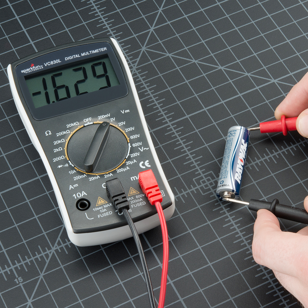
The multimeter is a device that combines several measurement functions in one single unit. At it’s minimum can measure Voltage, Resistance and Current. It also serves as a debugging tool to check for continuity between points in the circuit, either intentional or unintentional.
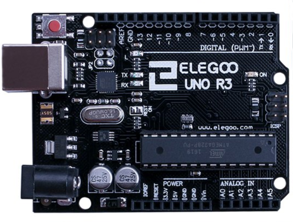
Arduino Uno
Arduino is an open source electronics prototping platform grouping hardware and software and offers different boards adaptable to wearables (LilyPad). It is important to start off with Arduino Uno. You have to program your Arduino through the IDE. It uses its own language which is a subpart of C++.
Analog pins are on the short line and the digital pins are one the long line. Pin 13 is already set to blink, and it is connected to the blinking LED. It is not possible to read a code encoded in an Arduino chip (you can only upload it from the computer to the chip but not the other way round).
Here are some important commands to program something on Arduino
// is like # in python, it allows to write text that will not be executed when running the code, allowing to put comments next to the code.

Before starting a function, we can initialize variables.
int VariableName=value;       variable is a whole number
float VariableName=value;     variable is a decimal number
bool variable;                variable is a boolean

Void means "function". There are two types of functions:
void setup() {code}        action to make only once when the reset or power button are pressed
void loop() {code}         action to repeat indefinetly

||                         OR
&&                         AND

Inside the void setup() {}, we can decide to write some actions to execute.
setup(){
  pinMode (pinNumber, OUTPUT)
}

digitalWrite(pin, value);  gives a certain status of power to the pin of our choice (on or off)
analogWrite(pin, value);   gives a certain amount of power to the pin of our choice (0 to 255). Only works with the ~PWM pins.
delay(time)                waits the predicted time before doing the next command
if (condition)             exectute the action depending on the condition
  action
else                       dictates the action to do when the "if" condition is not respected
  action

Inside the void setup() {}, we can also decide to read the information from a source.
setup(){
  pinMode (pinNumber, INPUT)
}
digitalRead(pinNumber)     reads the values recieved on pin 9, only off and on
lecture = digitalRead(9)   gives the variable "lecture" the value of pin 9
analogRead(pinNumber)      reads the values recieved on pin 9, from 0 to 255
Steps to set parameters on Arduino to be able to push it to the hardware :
- Go to Tools > Board > Ardunio AVR Boards > Arduino Uno
- Go to Tools > Port > /dev/cu.usbmodem14401(Arduino Uno)
Blink function
The code is in one of the examples. Go to File > Examples > Basics > Blink
SENSORS :
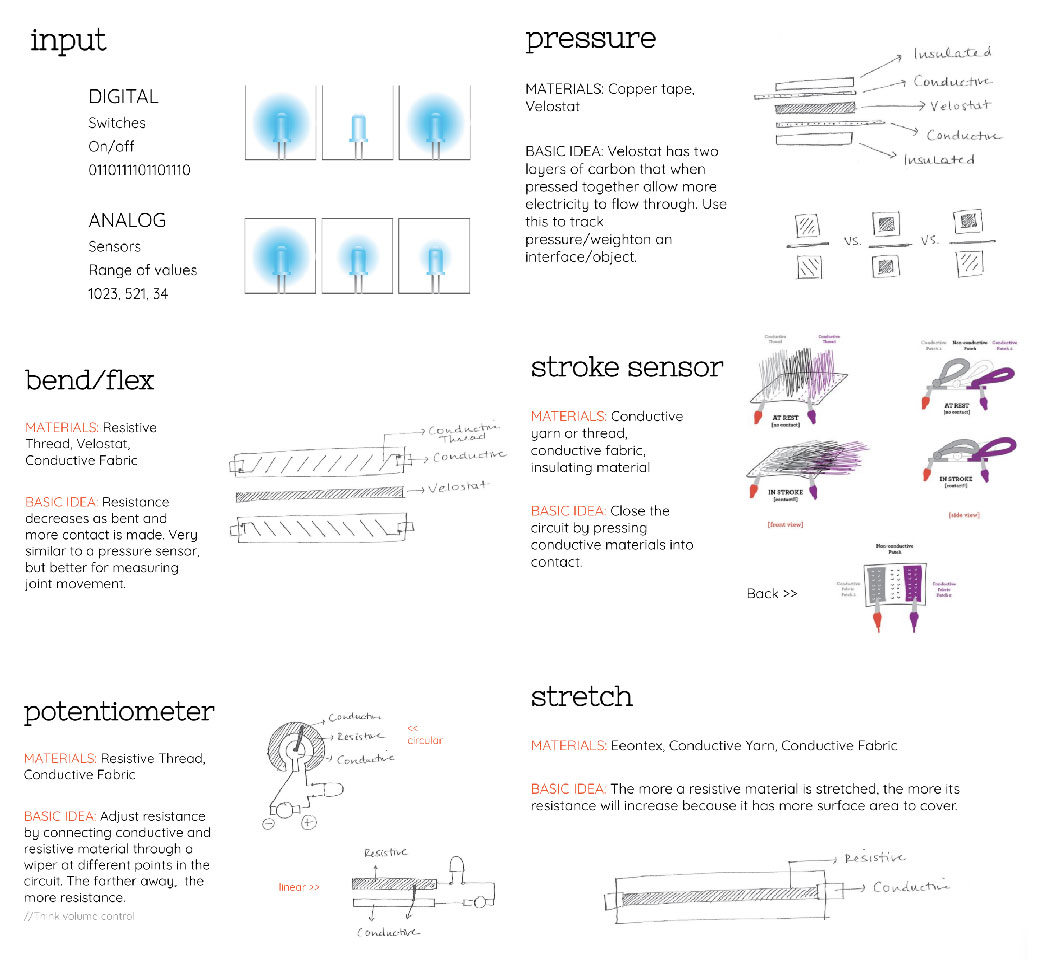
For this week's assignment we had to make 2 sensors - 1 Analog and 1 Digital and map their readings.
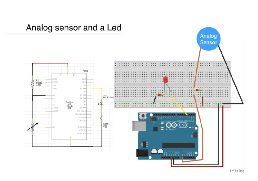
Analog Sensor
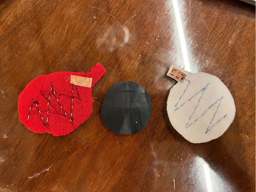
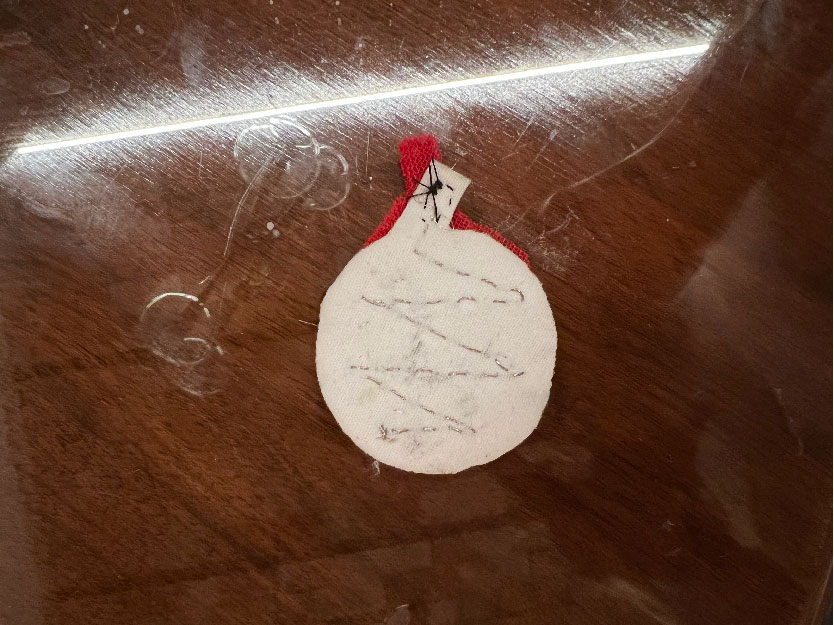
For the Analog sensor I wanted to make a pressure sensor. I made it using 2 non-conductive fabrics and velostat which is a conductive fabric.
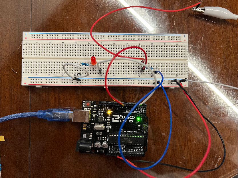
Circuit
Code
int lecture ;
int AnalogPin = A1 ;
int LED1 = 3;
int mapping;

void setup (){
  pinMode(AnalogPin, INPUT);
  pinMode(LED1, OUTPUT);
  Serial.begin (9600);
}

void loop (){
  lecture = analogRead (AnalogPin);
  mapping = map(lecture,800,1040,0,255);
  analogWrite(LED1, mapping);
  Serial.println (lecture);
  delay(100);
}
Here is a video of the sensor working.
Readings on the serial plotter
The values I received were from 800 to 1040 so I added them in the code for a better result
Readings on the serial monitor
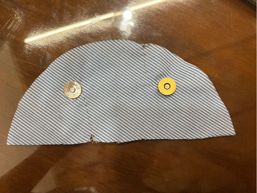
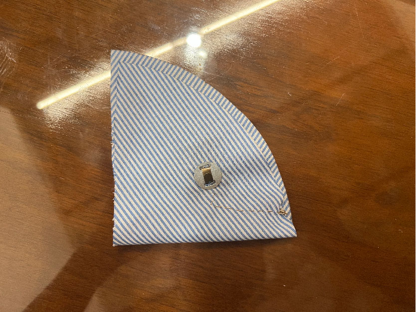
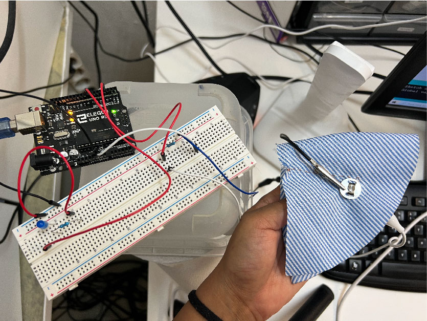
Digital Sensor
For the digital sensor I made a button switch using a metallic snap button which switches off when the button is closed and lights up on opening the button.
Cicuit

Code
int digital_sensor_pin = 8;
int digital_sensor_value = 0;
int led_pin = 3;

void setup() {
  // put your setup code here, to run once:
  pinMode(digital_sensor_pin, INPUT);
  Serial.begin(9600);
  pinMode(led_pin, OUTPUT);

}

void loop() {
  // put your main code here, to run repeatedly:
  digital_sensor_value = digitalRead(digital_sensor_pin);

  if(digital_sensor_value == HIGH){
    digitalWrite(led_pin, HIGH);
  } else {
    digitalWrite(led_pin, LOW);
  }
  Serial.println (digital_sensor_value);
  delay(100);
}
Here is a video of the sensor working.
Readings on the serial monitor
Readings on the serial plotter
Useful links
- Liza Stark
- Arduino Lilypad Shields
- Arduino Built-in Examples
- Arduino Programming Tutorial
- Pressure sensors
- Kobakant