WEEK 08. Wearables
References and inspirations
‘SHE IS NOT ALONE!’, Afrofuturist wearable devices for speculative PTSD treatment in Kenya
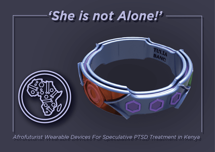
But with the work of Patricia Mwenda, who designed an "envisioned speculative wearable devices [which] consist of the Moyo Monitor designed to aid in continuous monitoring of PTSD associated with domestic abuse and the Tulia Band which is designed to aid in self-directed PTSD treatment" really embodies another vision of the world. It carries values and is here to really help.
I think that this week is a good way to create synesthesia.
Synesthesia (from greek syn, union, and aesthesis, sensation), is a phenomenon which consists in an unusual sensorial link, in which certain stimuli automatically evoke an aditional perception.(Cohen Kadosh & Henik, 2007).
It also can give some sort of "superpower" to human beings. You can link sound with objects, you can program motion to trigger light, etc.
Also, some sort of synesthesic language could be created with this kind of technology. We will see some tracks of it further down.
Students in the University of Antananarivo, Madagascar
 I think this is very interesting, since it gives another way of perceiving nature. It is another sort of communication.
Susanna Bauer

Susanna Bauer,'s work is so delicate, sensitive! To me, it translates the fragility of our world into something visually appealing.
This isn't Wearables at all, but I wanted to mention this work, since it inspired me in the choice of my week's theme.
Arduino
The following information were found on the french website of Developpez.com and on the following website.
These sites are french ones, for it helped get some subtle information I couldn't understand easily in English.
Syntaxic colors
Orange: keys words that Arduino recognizes to be existing functions.
When selecting an orange word: right click > "Find in reference" > opens, the documentation of the selected function.
Blue: key words that Arduino recognizes to be a constant.
Grey: comments that won't be executed by the program. It's useful to comment the code to avoid getting lost into it, or to make it understandable for someone else.
2 different ways to make a comment:
-in a line of code, everything after "//" is a comment
-several lines of code that we want to be comments can be circumscribed by "/" and "/"
Ponctuation
Every line of code ends will a semicolon ";"
A function content is delimited by braces "{" and "}"
Parameters of a function are held into brackets "(" and ")"
Function
What is a function?
A function is an instructions sequence that achieves a calculation or a task. It can contain input settings and can also return some output values.
A function must be stated one, and it can be called up at several occurences.
PinMode
pinMode(pin, mode)
-"Pin" being an allusion to the number of the pin on the Arduino board.
-"Mode": either input, output or input-pullup (this last one being an input when an internal resistance added to it)
What is this? Why do we use it?
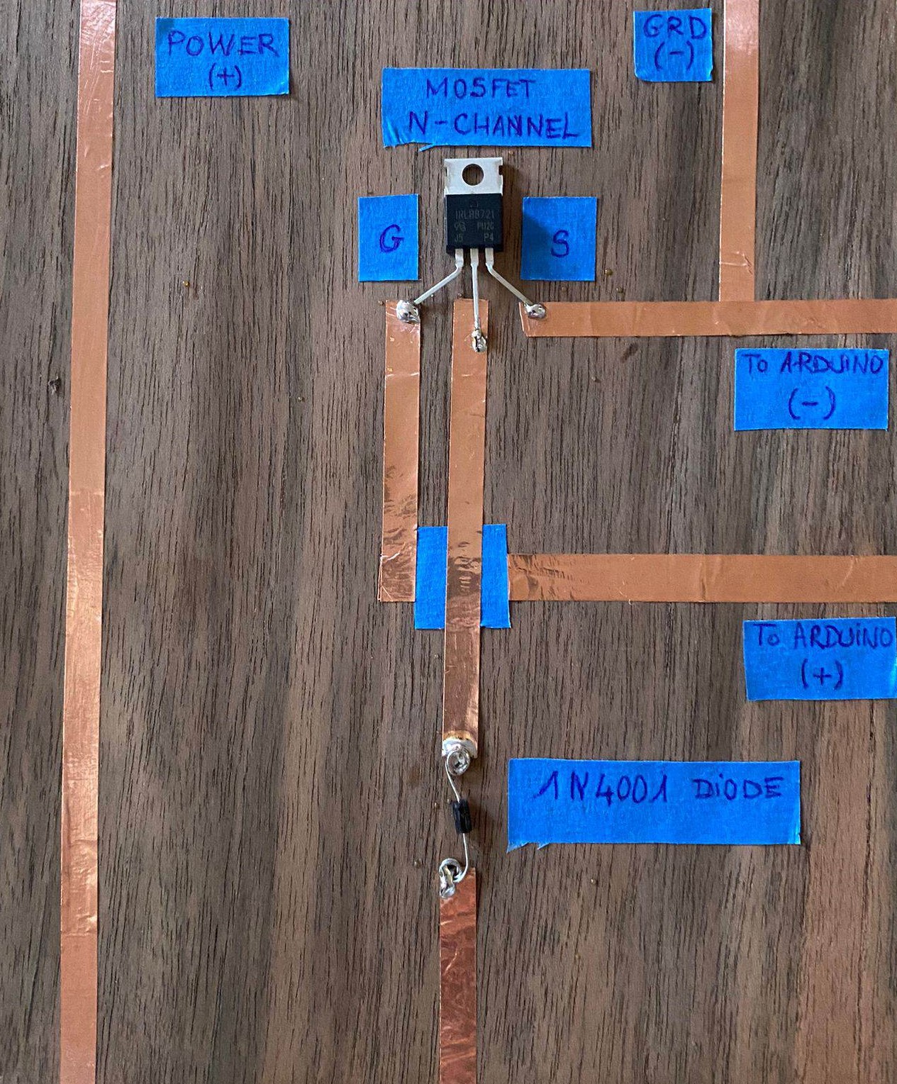
This component of the electrical circuit is a driver circuit. It allows to connect all your components to the Arduino Board and your output component (a speaker for instance) and to add a source of power to provide more Voltage to your electrical circuit. Some of the experiments with speakers or conductive pigments and inks require more Voltage to work.
To make this driver circuit, we had to solder the various component together.
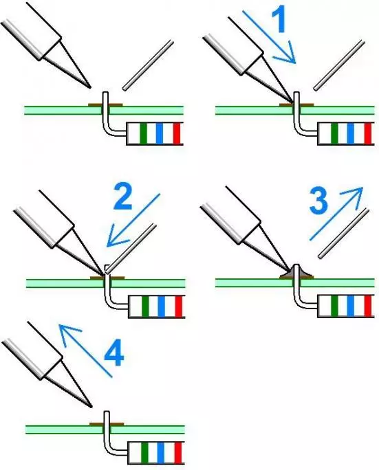
The technique we used was tin soldering, since it can be very precise, and it is mostly used when we deal with electrical boards and components.
* 1 soldering iron
- Some tin rods
- Protection glasses
- Protection gloves
* Prepare the surroundings of the soldering iron : clear and clean all around it.
- Put the soldering iron on the two components you want to solder together.
- Put the tin rod on the two components and the end of the soldering iron. The weld happens.
- Take off the tin rod when there is enough tin on the weld.
- Take off the soldering iron last. The next second, the weld is dry.
What is a transistor?
A transistor is a programed "switch" in an electrical circuit. It means that, depending on an electrical impulsion, it opens or closes, and delivers (or not if closed) a certain voltage of electricity to the negative part of the circuit. In our case, this impulsion (input) is given by Arduino (+) and the voltage output is transferred to the Arduino (-).
There are several types of transistors, depending on the output voltage needed, for example.
![]()
Picture found on Wikipedia
Testing the actuator sensors
About speakers
I suggest you to look at the work of Claire Williams
She works a lot with speakers, and on the site above, there is plenty of information on how to create a speaker that works.
Resistance and speakers
Sound is a matter of waves and wavelength. The principle of speakers is to convert electrical energy into mechanical energy (motion) thanks an eletro-magnet. A metallic coil creates a magnetic field when electrical current goes through it. When you invert the current's direction, it flips the magnet's poles.

Caption about the textile speakers
Mobile coil = the embroidered circuit onto the fabric
Paper cone = its role is done by the fabric. The lighter the fabric, the higher-pitched the sound.
Permanent magnet = a magnet you put onto your embroidered speaker
Electrical signal terminal = the electrical circuit you sew/embroider into your fabric.
Inside the speaker
The electro-magnet (mobile) is put in front of the permanent magnet (stationary). When electrical impulsers go through the electro-magnet coil, the direction of its magnetic field is suddenly changed, which means that the electro-magnet is alternatively attracted and rejected by the permanent magnet: it vibrates backwards and forwards.
The mechanical energy compresses the air and converts the movement into acoustic energy. The sound moves through pressure waves. The faster the air pressure changes, the faster the mobile coil moves, and the higher the sound frequency.
It is the backwards/forwards movement of the speaker that pushes the air particles, that consequently modifies the air pressure and creates acoustic waves.
8 Ohms for a speaker?
Before starting to create speakers, we wanted to know what material could be conductive enough to create a speaker.
We measured the resistance of some of them, in order to understand how we could work with it.
Some tests about resistance into the speakers
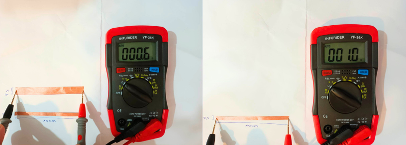
Here we measured the resistance of copper bands. We cut them precisely at 10 cm.
Result: Resistance seems to dicrease when the surface increase.
We were convinced that we absolutely needed 8 Ohms to create a working speaker, but this is mainly a choice related to the material you have in your lab. Speakers with 16 Ohms, 2 Ohms... also exist, but they require some other material!
In the next part, we will see that it is important that your resistance isn't too high whatsoever.
Tests
I tested two different speaker, with the exact same code.
First one; Diane Wakim's working speaker
This speaker was working like an calibration. I already knew it was working, so it would help me check on my circuit before testing another speaker.
I started by using Diane's speaker, the one she created two years ago, when she was attending Fabricademy program.
It allowed me to understand better the principle of the fabric speaker.

Using the StarWars music code, I obtained this:
Second one; mine!
Using a sewing machine, I embroiedered some fabric with a very dense zig zag stitch.
Because I was using this zig-zag stitch, I was expecting that the creation of a larger path for the electricity would reduce the resistance of my thread (an HC12 thread, as reference) in order to get to the 8 0hms resistance we needed in order to create a viable speaker.
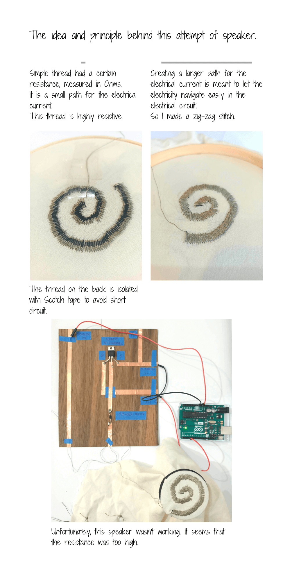
I tested my speaker with the exact same circuit and code than with Diane's speaker, and it wasn't working. Actually, when I measured the resistance of my embroidery, it appeared that it was higher than 130 Ohms!
Bill Of Materials
1 coil of HC12 conductive thread (for the upper sewing thread), 22m, 3,95€
1 coil of non conductive thread (for the sewing machine bobbin), 1,25€,
1 piece of scrap fabric
1 piece of scotch
1 sewing machine
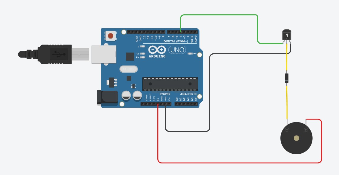
Here is a schema of the electrical circuit for the speaker :
Translating a music into Arduino's language
What you will need
1 Arduino UNO board
Several cables
An USB cable (to connect your computer to your Arduino Board)
Your speaker (see above)
The circuit driver (see above)
Still in my idea of creating a some object related to nature and the connection we can get with nature, I decided to translate some music which was linked with Nature, with a simple and recognizable melody. Very logically, I opted for "Colors of the Wind", a song played in Pocahontas, by Disney, since it is one of my favorite Disneys ever.
The music score of the melody

From this, I determined that the refrain was made with 8 music notes, which are right below:
Si - 247 Hz
Ré - 294 Hz
Mi - 330 Hz
Fa# - 370 Hz
La - 440 Hz
Si - 494 Hz
Do# - 554 Hz
Ré - 587 Hz
The number on the left are the frequencies linked to the music notes, depending on their octave. I calculated them thanks to translatorcafe's website
Frequency
Frequency is one of the characteristics of the sound (with the intensity and the duration), which indicates the number of vibrations per second, written in Hertz (Hz). A low frequency emits a low-pitched sound, when a higher frequency emits a high-pitched sound.
Here is the translated music score in Arduino
NOTE_FA,8, NOTE_LA,8, NOTE_REA,8, NOTE_DO,8, NOTE_DO,8, NOTE_SIM,8, NOTE_SIM,8,
NOTE_LA,8, NOTE_FA,8, NOTE_MI,8, NOTE_FA,4, NOTE_LA,4, NOTE_SIM,-4, REST,4,
NOTE_DO,8, NOTE_REA,8, NOTE_DO,8, NOTE_DO,8, NOTE_SIM,8, NOTE_SIM,8, NOTE_LA,8,
NOTE_LA,8, NOTE_FA,4, NOTE_LA,2, REST,4,
NOTE_FA,8, NOTE_LA,8, NOTE_REA,8, NOTE_DO,8, NOTE_DO,8, NOTE_SIM,8, NOTE_SIM,8,
NOTE_LA,8, NOTE_LA,8, NOTE_SIM,8, NOTE_LA,4, NOTE_REM,2, REST,4,
NOTE_SIG,8, NOTE_REM,8, NOTE_MI,8, NOTE_FA,8, NOTE_FA,8, NOTE_MI,8, NOTE_MI,8,
NOTE_REM,8, NOTE_REM,8, NOTE_SIG,8, NOTE_MI,-2, REST,4,
NOTE_SIG,8, NOTE_REM,8, NOTE_MI,8, NOTE_FA,8, NOTE_FA,8, NOTE_MI,8, NOTE_MI,8,
NOTE_REM,8, NOTE_SIG,8, NOTE_REM,8, NOTE_REA,1, REST,4,
The number against each coded music note represents its duration, according to this scheme:
8 = a eighteenth
4 = a quarter
2 = a half note
1 = a whole note
Here is the code for this music
/*
  Color of the Wind, Judy Kuhn, Pocahontas
  Connect a piezo buzzer or speaker to pin 3 or select a new pin.

*/
// programming the different music notes
#define NOTE_SIG  247
#define NOTE_REM  294
#define NOTE_MI 330
#define NOTE_FA  370
#define NOTE_LA 440
#define NOTE_SIM  494
#define NOTE_DO  554
#define NOTE_REA 587
#define REST      0


// change this to make the song slower or faster
int tempo = 60;

// change this to whichever pin you want to use
int buzzer = 3;

// notes of the melody followed by the duration.
// a 4 means a quarter note, 8 an eighteenth , 16 sixteenth, so on
// !!negative numbers are used to represent dotted notes,
// so -4 means a dotted quarter note, that is, a quarter plus an eighteenth!!
int melody[] = {

  // Color of the Wind theme (Judy Kuhn) - Pocahontas
  // Singing part

  NOTE_FA,8, NOTE_LA,8, NOTE_REA,8, NOTE_DO,8, NOTE_DO,8, NOTE_SIM,8, NOTE_SIM,8,
  NOTE_LA,8, NOTE_FA,8, NOTE_MI,8, NOTE_FA,4, NOTE_LA,4, NOTE_SIM,-4, REST,4,

  NOTE_DO,8, NOTE_REA,8, NOTE_DO,8, NOTE_DO,8, NOTE_SIM,8, NOTE_SIM,8, NOTE_LA,8,
  NOTE_LA,8, NOTE_FA,4, NOTE_LA,2, REST,4,

  NOTE_FA,8, NOTE_LA,8, NOTE_REA,8, NOTE_DO,8, NOTE_DO,8, NOTE_SIM,8, NOTE_SIM,8,
  NOTE_LA,8, NOTE_LA,8, NOTE_SIM,8, NOTE_LA,4, NOTE_REM,2, REST,4,

  NOTE_SIG,8, NOTE_REM,8, NOTE_MI,8, NOTE_FA,8, NOTE_FA,8, NOTE_MI,8, NOTE_MI,8,
  NOTE_REM,8, NOTE_REM,8, NOTE_SIG,8, NOTE_MI,-2, REST,4,

  NOTE_SIG,8, NOTE_REM,8, NOTE_MI,8, NOTE_FA,8, NOTE_FA,8, NOTE_MI,8, NOTE_MI,8,
  NOTE_REM,8, NOTE_SIG,8, NOTE_REM,8, NOTE_REA,1, REST,4,


};

// sizeof gives the number of bytes, each int value is composed of two bytes (16 bits)
// there are two values per note (pitch and duration), so for each note there are four bytes
int notes = sizeof(melody) / sizeof(melody[0]) / 2;

// this calculates the duration of a whole note in ms
int wholenote = (60000 * 4) / tempo;

int divider = 0, noteDuration = 0;

void setup() {
  // iterate over the notes of the melody.
  // Remember, the array is twice the number of notes (notes + durations)
  for (int thisNote = 0; thisNote < notes * 2; thisNote = thisNote + 2) {

    // calculates the duration of each note
    divider = melody[thisNote + 1];
    if (divider > 0) {
      // regular note, just proceed
      noteDuration = (wholenote) / divider;
    } else if (divider < 0) {
      // dotted notes are represented with negative durations!!
      noteDuration = (wholenote) / abs(divider);
      noteDuration *= 1.5; // increases the duration in half for dotted notes
    }

    // we only play the note for 90% of the duration, leaving 10% as a pause
    tone(buzzer, melody[thisNote], noteDuration*0.9);

    // Wait for the specief duration before playing the next note.
    delay(noteDuration);

    // stop the waveform generation before the next note.
    noTone(buzzer);
  }
}

void loop() {
  // no need to repeat the melody.
}
And... here is the result!!
Lyrics
Have you ever heard the wolf cry to the blue corn moon
Or asked the grinning bobcat why he grinned
Can you sing with all the voices of the mountain
Can you paint with all the colors of the wind
Can you paint with all the colors of the wind"
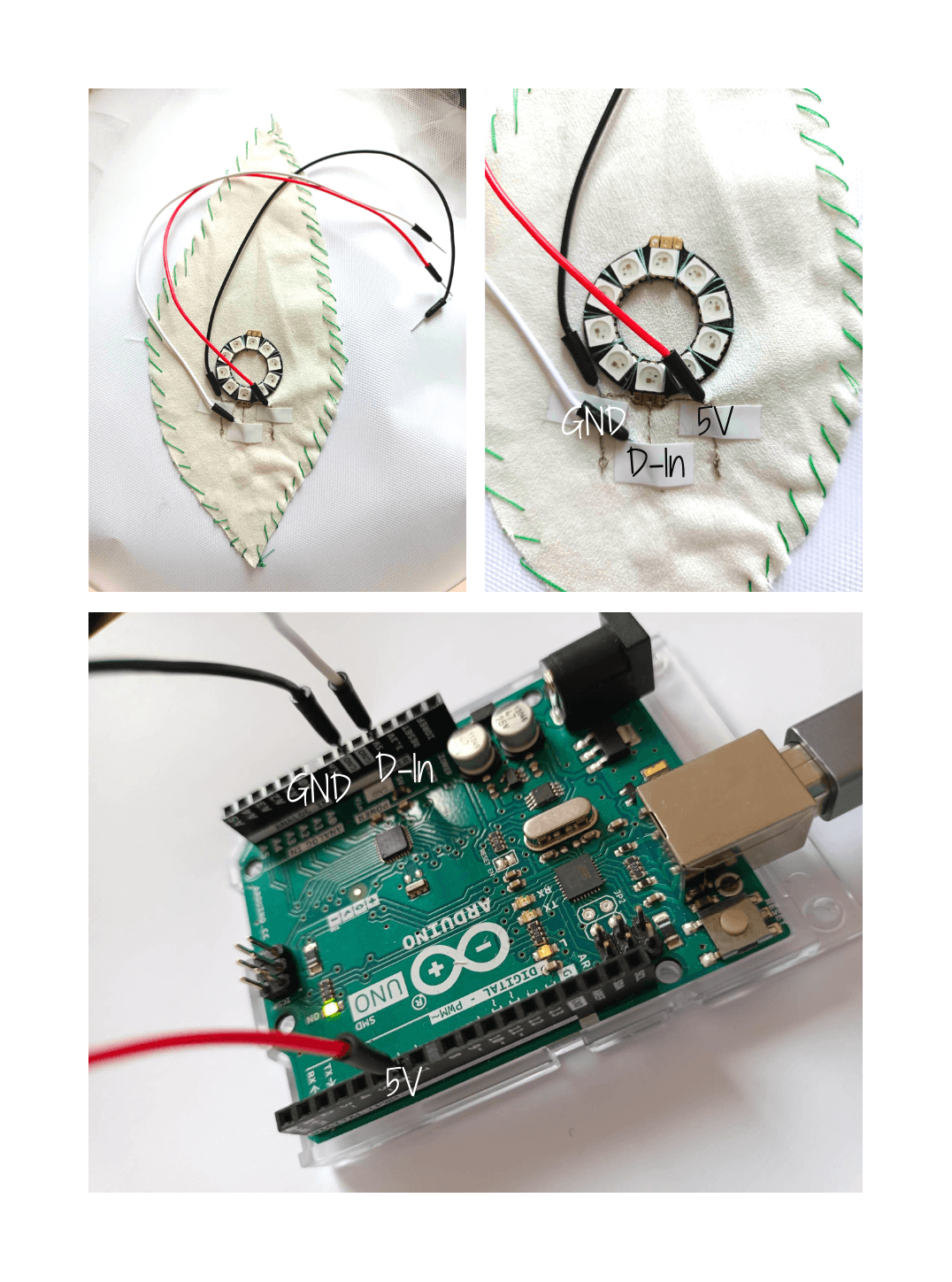
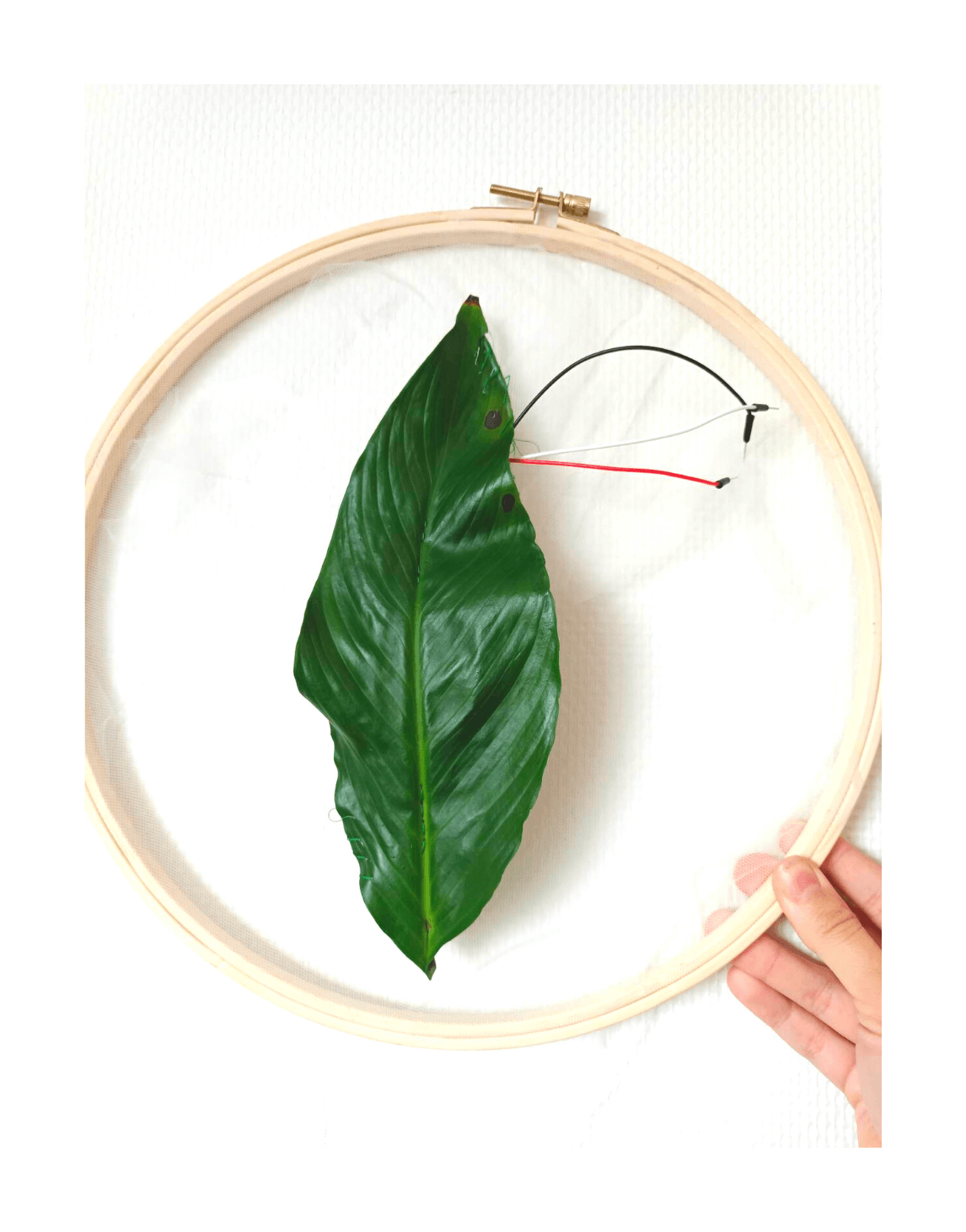
About Neopixels : the heart of a leaf
Still in this idea of working around the theme of nature, I decided to display a visible "heart" for a leaf.
For this matter, I will use Neopixels.
You will need:
1 Arduino Uno board
Some Neopixels (I use a round one with 10 Neopixels), but here you can find one with 12 Neopixels
3 conductive cables
Some conductive thread (Reference : HC40)
1 embroidery circle
A piece of scrap fabric (that you can embroider)
A leaf of your choice.
The goal is to set up one Neopixel, and make it blink in the idea of a beating heart.
Code modifications
/*
 * Emma Pareschi
 * Modified by Laora Guillerm
 * Basic commands of Library Adafruit_NeoPixel
 * Using some parts from the example "strandtest"
 */

#include <Adafruit_NeoPixel.h>

// Which pin on the Arduino is connected to the NeoPixels?
#define PIN            6

// How many NeoPixels are attached to the Arduino?
#define NUMPIXELS      10


// Declare our NeoPixel pixels object:
Adafruit_NeoPixel pixels = Adafruit_NeoPixel(NUMPIXELS, PIN, NEO_GRB + NEO_KHZ800);
// Argument 1 = Number of pixels in NeoPixel strip
// Argument 2 = Arduino pin number (most are valid)
// Argument 3 = Pixel type flags, add together as needed:
//   NEO_KHZ800  800 KHz bitstream (most NeoPixel products w/WS2812 LEDs)
//   NEO_KHZ400  400 KHz (classic 'v1' (not v2) FLORA pixels, WS2811 drivers)
//   NEO_GRB     Pixels are wired for GRB bitstream (most NeoPixel products)
//   NEO_RGB     Pixels are wired for RGB bitstream (v1 FLORA pixels, not v2)
//   NEO_RGBW    Pixels are wired for RGBW bitstream (NeoPixel RGBW products)


//pack the color in one variable

uint32_t white = pixels.Color(255, 255, 255);
uint32_t off = pixels.Color(0, 0, 0);

int delayval1 = 100; // delay for 100 milliseconds / time of the pulsation, light on
int delayval2 = 500; // delay for 500 milliseconds / longer pause before the heart pulses again.
int delayval3 = 100; // delay for 100 milliseconds / little pause between the blood-in/blood-out of the heart
// I set up 3 different delayvals to be able to modify it to my convenience.

void setup() {

  pixels.begin(); // This initializes the NeoPixel library.
  pixels.show();            // Turn OFF all pixels ASAP
  pixels.setBrightness(**30**); //from 0 to 255, use it only in setup

}

void loop() {

  pixels.setPixelColor(0, white); //set the color white on the first pixel/ first pulsation, blood in
  pixels.show();  //display the color
  delay(delayval1);

  pixels.setPixelColor(0, off); //set no color on the first pixel/ it's the little pause between the blood-in/blood-out of the heart
  pixels.show();  //display the color
  delay(delayval3);

  pixels.setPixelColor(0, white); //set the color white on the first pixel/ second pulsation, blood out
  pixels.show();  //display the color
  delay(delayval1);

  pixels.setPixelColor(0, off); //set no color on the first pixel/ longer pause before the heart pulses again
  pixels.show();  //display the color
  delay(delayval2);


}
/*
 * Emma Pareschi
 * Modified by Laora Guillerm
 * Basic commands of Library Adafruit_NeoPixel
 * Using some parts from the example "strandtest"
 */

#include <Adafruit_NeoPixel.h>

// Which pin on the Arduino is connected to the NeoPixels?
#define PIN            6

// How many NeoPixels are attached to the Arduino?
#define NUMPIXELS      10


// Declare our NeoPixel pixels object:
Adafruit_NeoPixel pixels = Adafruit_NeoPixel(NUMPIXELS, PIN, NEO_GRB + NEO_KHZ800);
// Argument 1 = Number of pixels in NeoPixel strip
// Argument 2 = Arduino pin number (most are valid)
// Argument 3 = Pixel type flags, add together as needed:
//   NEO_KHZ800  800 KHz bitstream (most NeoPixel products w/WS2812 LEDs)
//   NEO_KHZ400  400 KHz (classic 'v1' (not v2) FLORA pixels, WS2811 drivers)
//   NEO_GRB     Pixels are wired for GRB bitstream (most NeoPixel products)
//   NEO_RGB     Pixels are wired for RGB bitstream (v1 FLORA pixels, not v2)
//   NEO_RGBW    Pixels are wired for RGBW bitstream (NeoPixel RGBW products)


//pack the color in one variable

uint32_t white = pixels.Color(255, 255, 255);
uint32_t off = pixels.Color(0, 0, 0);

int delayval1 = 100; // delay for half a second
int delayval2 = 500;
int delayval3 = 100
;


void setup() {

  pixels.begin(); // This initializes the NeoPixel library.
  pixels.show();            // Turn OFF all pixels ASAP
  pixels.setBrightness(30); //from 0 to 255, use it only in setup

}

void loop() {

  pixels.fill(white, 0, 10);
  pixels.show();
  delay(delayval1);

  pixels.fill(off, 0, 10);
  pixels.show();
  delay(delayval3);

  pixels.fill(white, 0, 10);
  pixels.show();
  delay(delayval1);

  pixels.fill(off, 0, 10);
  pixels.show();
  delay(delayval2);

}
pixels.setPixelColor(0, white)
to this:
pixels.fill(white, 0, 10);
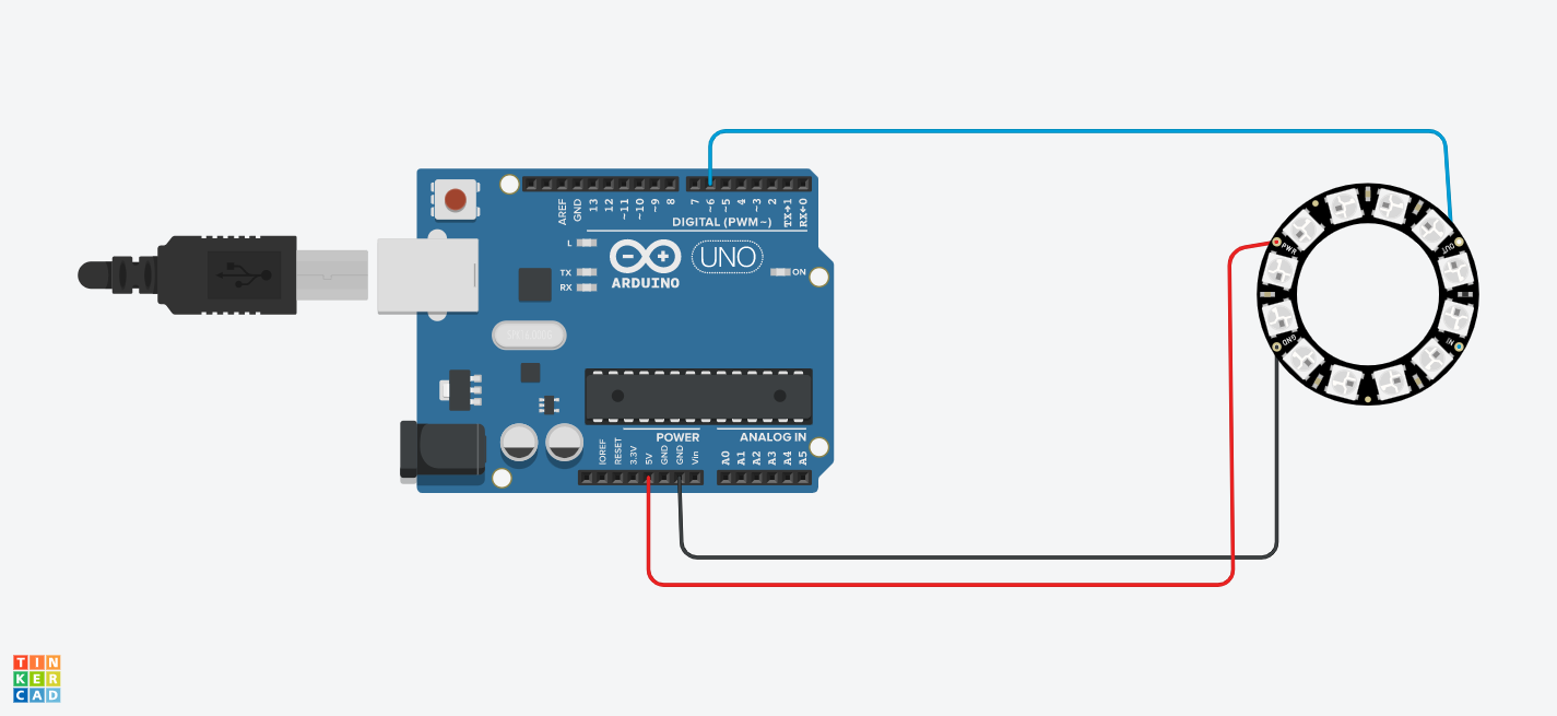
Caption
white = the color I coded above.
0 = first LED affected by this color.
10 = the number of LED (from the LED O) affected by this color.
Enlighted morse language?
With the blinking of the light, we could translate spoken language into morse.
The notion of communication and synesthesia of language is important here.
The following extract says "Grab the wind, paint with it." It is an invitation to follow the breath of wind.
With just some modifications of the code above, I could get to the result of enlighted morse.
It is another way of communicating information, and it makes sense when we know that morse is an international language..!
To be continued...
Generating the "color of the wind"
Still thinking about the idea of synesthesia, what I want here is to connect the power of wind (converted in Volt through motion) and colorful light (through LEDs), just like in the song "Color of the Wind" coded above.
What I am trying to design is an hypothetical project, because I don't have any anemometer. No matter what, it was interesting learning things about it.
The Anemometer

The anemometer captor is an analogical captor. Its function is to measure the wind's speed thanks to an helix-type captor.
Two calibers: 5 to 20 km/h 5 to 100 km/h
State: Send back a tension from 0,5 to 5V
2 measuring ranges:
From 5km/h to 20km/h
5km/h = 0,5V
20 km/h = 5V
From 5km/h to 100 km/h
5km/h = 0,5V
100km/h = 5V
A captor with hall effect is placed under the printed circuit near the hole where is placed the helix. A magnet situated into the spigot of the helix is detected by the captor with hall effect. A calculator tranforms the number of number of rotations in a Voltage from 0 to 5V in proportion with its speed.
Sensor Hall Effect
Sensor Hall Effect
I found a very clear video about this tool, made by "How to Mechatronics", in which you find the schema below.
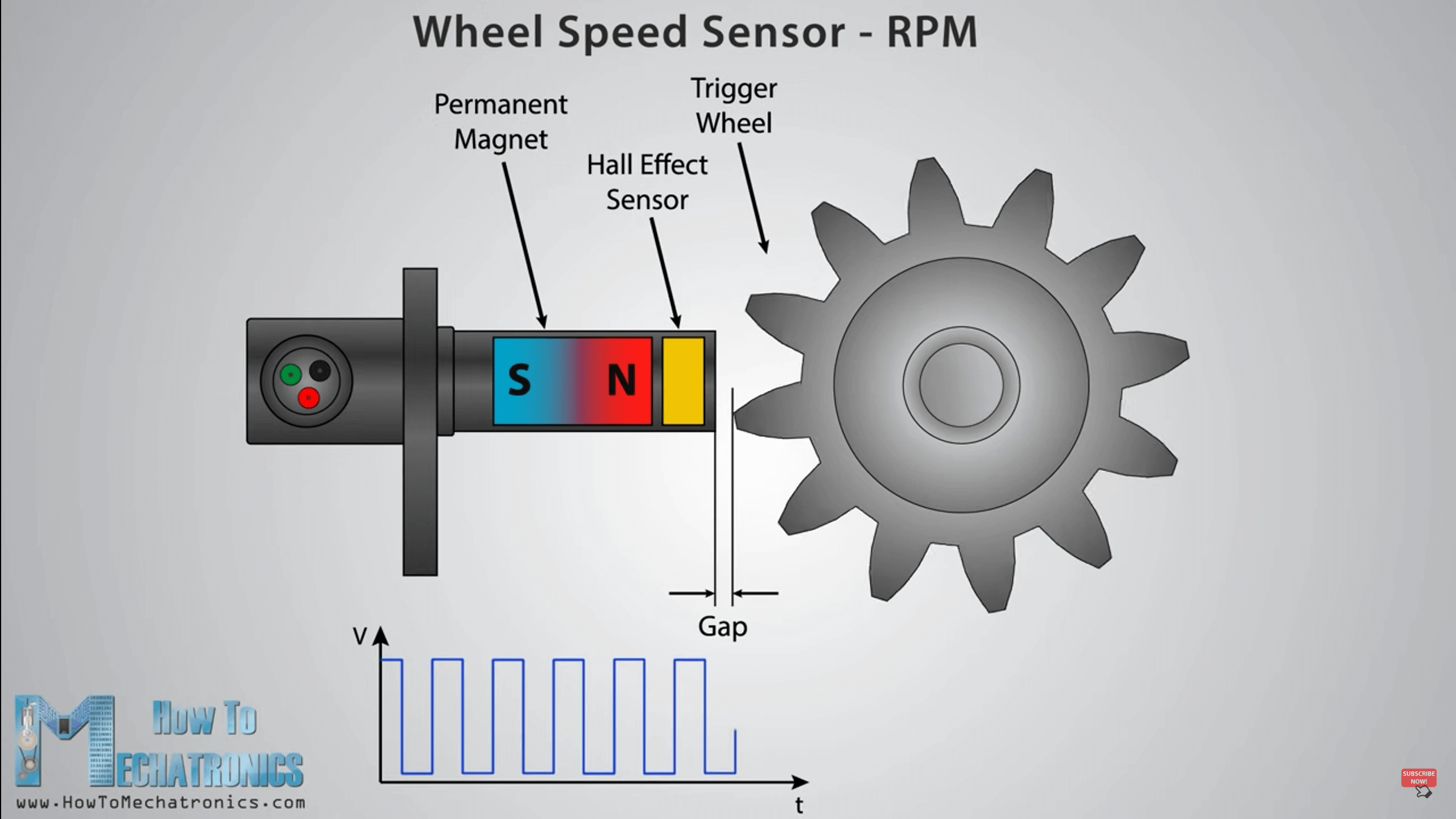
Sensor Hall effect is the effect to be able to measure a Voltage thanks to the reaction between a magnetical field and an electrical current; one of them is the speed of a turning wheel. This is exactly what happens when measuring the speed of the wind. The wind makes the wheel turn, and the trigger wheel, each time it goes near the Hall effect sensor, changes the surrounding magnetic field (that is caused by the permanent magnet.)
Modidying existing codes to match them with my idea
Coding the colors
Original unmodified piece of code
Found on this site
void setup() {
pinMode(13, OUTPUT);
pinMode(4, INPUT);
}
// Boucle principale:
void loop() {
int BP = digitalRead(4); // Lecture du capteur
if (BP == LOW) {
digitalWrite(13, HIGH); // Allume la Led
}
else {
digitalWrite(13, LOW); // Eteind la Led
}
}
What I want is to condition the LED to ignite in a certain color depending on the measured speed of wind, calculated by the anemometer.
So, I modified the code above into:
The modifications
void setup() {
pinMode(13, OUTPUT);
pinMode(4, INPUT);
}
// Boucle principale:// principal loop
void loop() {
int BP = digitalRead(4); // Lecture du capteur
for (BP < 5) {
digitalWrite(13, 255, 134, 106); // Light on the LED in tea rose
}
for (BP < 10) {
digitalWrite(13, 158, 253, 56); // Light on LED in lime green
}
for (BP < 15) {}
digitalWrite(13, 189, 51, 164); // Light on the LED in byzantin
}
for (BP < 20) {
digitalWrite(13, 108, 2, 119); // Light on the LED in zizolin
}
}
Nonetheless, what is missing here is the principal loop. What is inside? How does it measure anything?
Analog and digital pins
When you write your program, check the pinMode you are using.
1>13 are digital pins
A0>A5 are capable of dealing with analog captors.
Determining the analog values
Analog entry allow to read the analogical values of a voltage (which varies from 0 to 5V). This reading is discretised with a 10 bits resolution, that is to say 1024 values, goign from 0 to 1023.
The higher the voltage will be on the pin, the higher the read value will be. Consequently, a voltage of 5V on an analogical pin will be analogically read as 1023, as 0 if the voltage is equal to 0V, and as 511 if the voltage is equal to 2,5V.
Tinkering with Arduino : adding the notion of wind
Looking for the principal loop for the previous code right above, I researched some ways to code the measuring of wind speed with an anemometer, and how to connect it to the Arduino Uno board.
Original unmodified piece of code. Found on this site.
#define pinILS 12
#define pi 3.14159265359
#define RayonDesBras   0.1 // en mètre de l'anénomètre

void setup()
{
  pinMode(pinILS, INPUT); // this is the anemometer
  pinMode(pinA0, OUTPUT); //
  Serial.begin(9600); //
}

unsigned long millis_old(0);
float deltaTime(0);
float vitesseVent(0); //speed of the wind
float NombreTourSec(0);
float FEtalonnage(1);

bool isActive(false);

void loop()
{
    UpdateILS();
    //convertion periode -> fréquence
    NombreTourSec = (1 / deltaTime);
    //vitesse du vent

    vitesseVent = 2*pi*RayonDesBras*NombreTourSec*FEtalonnage;
    //affichage de la vitesse
    Serial.print("la vitesse du vent est de ");
    Serial.println(vitesseVent);
    Serial.print(" m/s.");
}
void UpdateILS()
{
    //lecture du capteur
    isActive = digitalRead(pinILS);

    if(isActive)
    {
        deltaTime = (millis() - millis_old) / 1000 ; // div en 1000 pour avoir le résultat en sec
        millis_old = millis(); // remise à 0 du compteur pour capturer la différence de temps au prochain tour
    }
}
Millis
Millis is a very convenient tool used in Arduino language, to express a certain temporality.
The modifications
#define pinILS 12
#define pi 3.14159265359
#define RadiusOfBeam    0.1 // en mètre de l'anénomètre
#define pin A0   //this is the LED

void setup()
{
  pinMode(pinILS, INPUT);
  Serial.begin(9600);//to allow the display of values on the serial monitor
}

unsigned long millis_old(0);
float deltaTime(0);
float WindSpeed(0); //speed of the wind
float NumberTurnSec(0);
float FEtalonnage(1);

bool isActive(false);

void loop()
{
    UpdateILS();
    //convertion periode -> fréquence
    NumberTurnSec = (1 / deltaTime);
    //vitesse du vent

    WindSpeed = 2*pi*RadiusOfBeam*NumberTurnSec*FEtalonnage;
    //affichage de la vitesse
    Serial.print("la vitesse du vent est de ");
    Serial.println(vitesseVent);
    Serial.print(" m/s.");
}
void UpdateILS()
{
    //lecture du capteur
    isActive = digitalRead(pinILS);

    if(isActive)
    {
        deltaTime = (millis() - millis_old) / 1000 ; // div en 1000 pour avoir le résultat en sec
        millis_old = millis(); // remise à 0 du compteur pour capturer la différence de temps au prochain tour
    }
  for (WindSpeed < 5) {
  digitalWrite(13, 255, 134, 106); // Light on the LED in tea rose
  }
  for (WindSpeed < 10) {
  digitalWrite(13, 158, 253, 56); // Light on LED in lime green
  }
  for (WindSpeed < 15) {
  digitalWrite(13, 189, 51, 164); // Light on the LED in byzantin
  }
  for (WindSpeed < 20) {
  digitalWrite(13, 108, 2, 119); // Light on the LED in zizolin
  }
  }