2. Digital bodies
Fashion is in some way the art of covering bodies. Bodies come in different shapes and sizes and are crucial parameters of fashion as they are the converse for the making of new clothes. However, since the industrialization and the era of ready-to-wear clothes and fast fashion, bodies also became subject to trends as beauty standards varied. It is therefore crucial to understand the proportions of the body to know how to adapt clothes to different sizes, whether it is for mass production with standard sizes or tailored clothes. The notion of digital bodies refers to the digital representation of bodies in the era of pandemic-caused remote events, online shopping and online communication. Digital bodies can be useful for the presentation of products on websites (use of an avatar for the presentation of the fall-winter 2020-2021 collection by Ralph & Russo, online custom-made clothes brands using the client's measurements, non-physical clothes from digital fashion houses (DressX, The Fabricant), drawing of clothes for the metaverse (non-fungible tokens on Decentraland). These new digital tools can be a great asset if we aim to get out of the mass production era and eventually help us make better fitting and more unique clothes.
I-Research
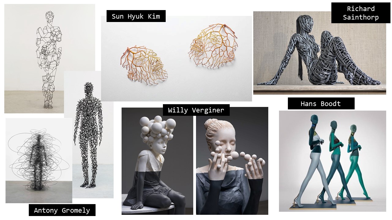
During the lecture, many artists with different ways and techniques to represent the human body were presented to us. Among them, some of them particularly inspired me, like Antony Gormley and Sun Hyuk Kim. I particularly liked their detailed representation of the human body and figure using lines and geometrical structures while still leaving a big space to the void. I was also touched by Willy Verginer's work with the two-tone demarcation and the surrealist shapes, giving a very soft result. Doing some more research, I came across the work of Richard Stainthorp who represents bodies without faces using metallic wires, again leaving room for emptiness but still conveying movement and vitality. In a more commercial field, I also liked Hans Boodt's mannequins for the mix of colors and materials as well as for their very pure style which nevertheless allows to transmit movement and even emotions.
II-Assignment
The goal of the week was to learn about the human body, its proportions and its various representations, physical or digital. We leart how to represent a human body on the MakeHuman software, but also how to scan our own body using a 3D scanner. We were taught how to modify the 3D models that were obtained on MakeHuman or by 3D scanning and made our own mannequin out of wood, cardboard or paper according to the technique we wanted. To do so, we learnt how to use the "Slicer for Fusion" software and finally how to use the lasercutter for the cutting of the pieces.
III-3D scanning: Skanect
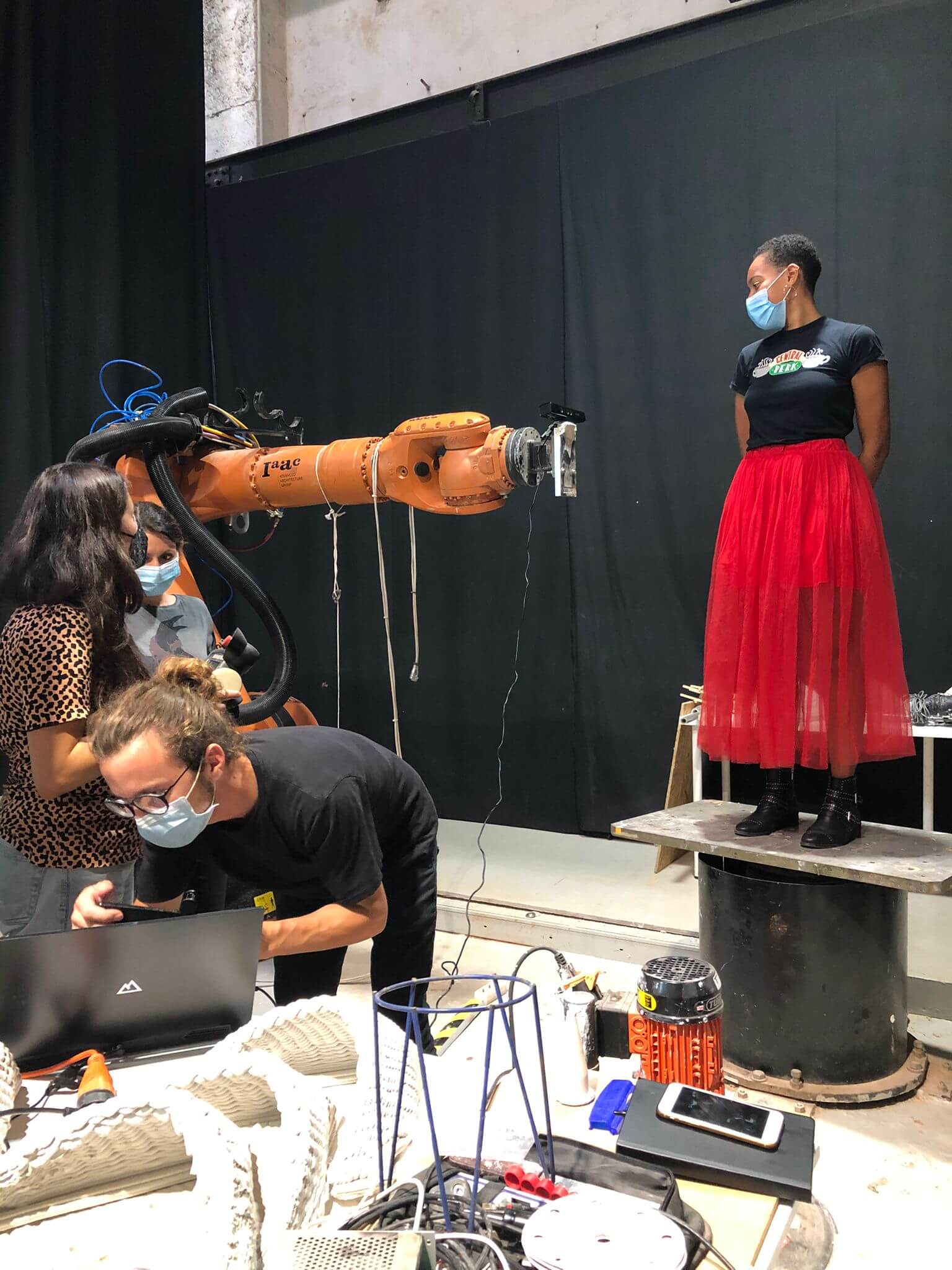
3D scanning allows to have digital 3D images of real-life objects. To 3D scan something, one needs a camera and a depth sensor. Expensive tools exist to 3D scan objects, but cheaper solutions have been developped by diverting objects of everyday life. That is how the milkscan was developped, allowing to capture the depth of an object by immerging an object in a certain volume of milk, capturing an image of it and then adding the same amount of milk and repeting the steps. However, this technique does not allow to scan non-waterproof (or milkproof) objects without damaging them, nor big objects. Fabricademy Amsterdam uses the iScan device which is a 3D scanner that has two cameras and a depth sensor. At Fabricademy Barcelona, the tool used is called Skanect which uses the kinect from the Xbox 360 to get 3D images. We put it on the Kuka Robotic arm to move the kinect sensor in a more regular way that it would have been if it was held by hand, and the person to be scanned (me) was displayed on a turning socle.
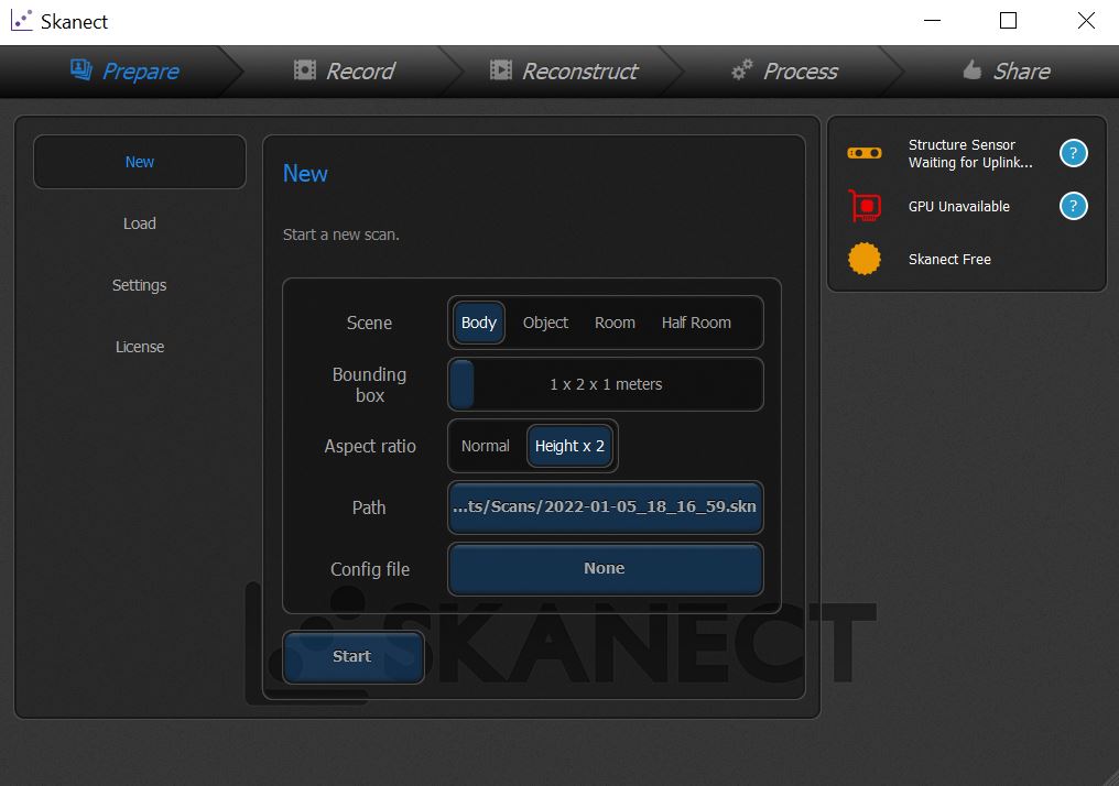
To skan something using the Skanect application, one should first prepare the object to be scanned in the "Prepare" tab. We set the scene to "body" and used a ratio of 2*1 since I was scanned standing with my arms up.
Then, once the kinect is connected and the preparation settings are done, we can start recording. While turning, the robotic arm needs to be sliding up and down several times to have a complete scan of the person. Once the scanner has scanned the subject around 3 times and is shown in green on the app, the scanning can stop.
Finally, we can process the mesh by selecting the "watertightness" option and thus having a closed mesh. The mesh can then finally be exported.
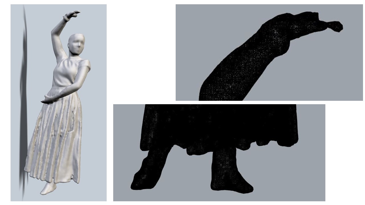
And here is the result of my 3D scan. The settings used for the scanning were not matching the pose I did so I ended up having cut feet. The scanner also did not capture the small details like my hand but the overall result with a very tight mesh is quite impressive!
IV-MakeHuman
MakeHuman is a free software allowing the user to create a 3D character thanks to a "basic human" that can be modeled to taste modulating a large range of features such as ethnicity, gender, size, weight, muscularity, skin colour, facial features, facial expressions and body positions. The interface was really easy to understand and user friendly, so I had no problem realizing what I had in mind.
In the "modelling" tab, the general body of the human can be determined, either qualitatively or by directly inputing the measurements in the "measure" sub tab. The "geometries" tab allows to pick out clothes and define facial features. "Materials" is for the skin color and "Pose/Animate" is for the pose of the mannequin.
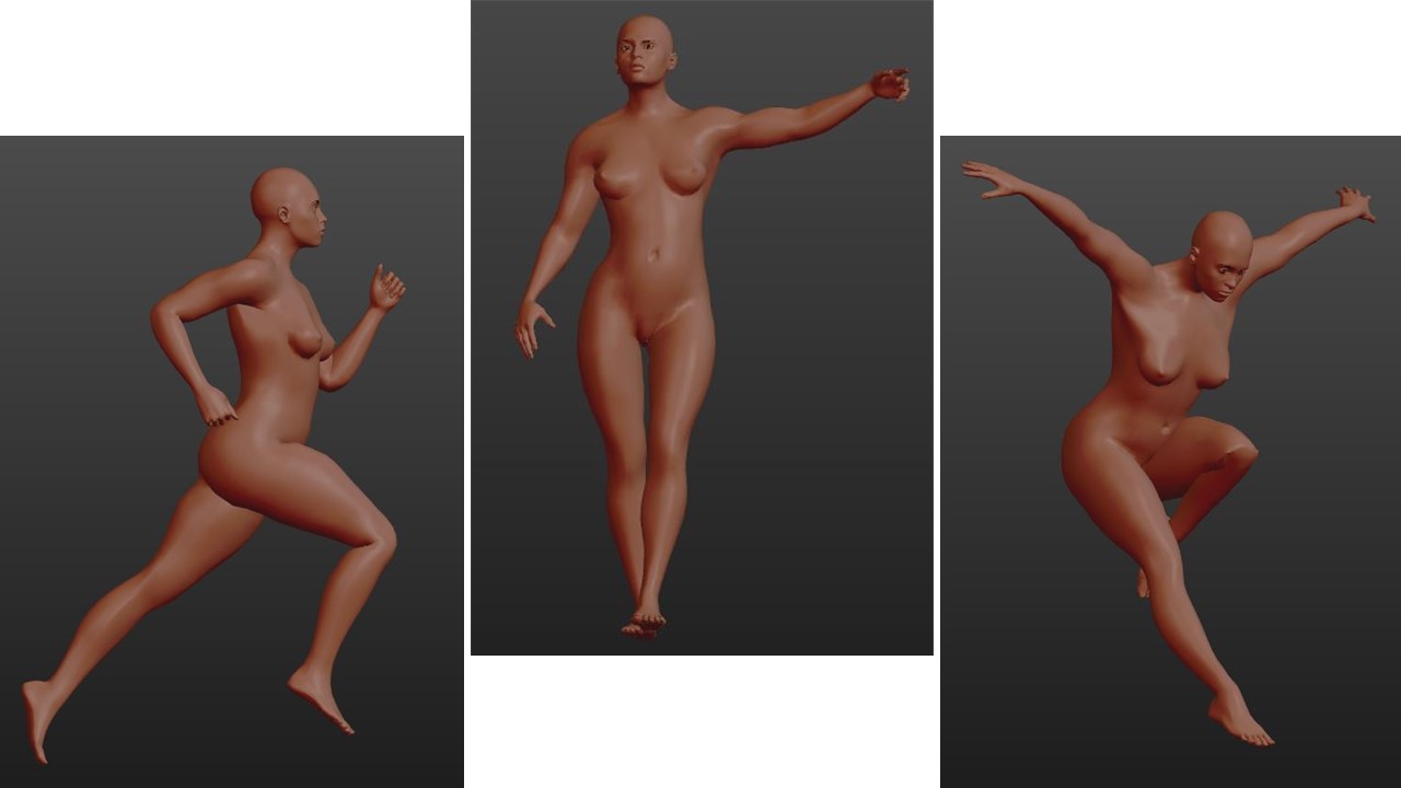
 For my final mannequin, I wanted to represent my own body and adopt a pose that expressed softness or movement. I settled for a soft pose with one outsteched arm as if the character wanted to reach something.
The final model can be exported in the .stl format and be modified on Rhinoceros3D.
V-Rhinoceros 3D
Rhinoceros3D is the first software of 3D I ever used (apart from softwares for protein and other molecules modelisation) so I was really scared to be lost but after the tutorial (and some re-watching of the tutorial hihihi), I got the logic behind it and could model easy elements or modify structures without effort. During the tutorial, we learnt how to draw shapes in the different views (frond, side, top and perspective), the difference bitween lines, closed lines, 2D surfaces, 3D objects and meshes and how to change from one to another. We also learnt how to switch from one to another (3D objects from a 2D plan surface or a closed line, mesh to a solid) and how to modify these objects by trimming them, capping them or merging them together.
In Rhinoceros3D, there are 3 ways to do the same operation: using the menu on the left, the top menu or command lines. Here are some examples of command lines and their effect:
Polyline                     Traces a 2D line with multiple tops.
Extrude                      Turns a 2D element into a 3D element by giving it a given depth.
Revolve                      Creates a 3D element from a polyline by rotating it around an axis.

Divide                       Divides a line/polyline into a certain number of fragments.
Trim                         Trims an object according to a cutting element.
Split                        Cuts an object according to a cuttinf element but keeps the different cutted parts.
Cap                          Adds a surface to an open polysurface to close it, only if the opening is planar.

BoundingBox                  Creates a box arounf the selected geometry and gives the measurments.
Mirror                       Traces the axial symetry of a selected element according to an axis.
ShowEdges                    Shows the naked edges of a polysurface.
Rotate                       Rotates an object according to a point (only on planar view).

BooleanSplit                 Takes two intersecting 3D objects and divides it into X distinctobjects keeping all the elements.
BooleanDifference            Takes two intersecting 3D objects and divides it into X distinct objects deleting the desired parts.
BooleanIntersection          Takes two intersecting 3D objects and only keeps the intesection of the two.
BooleanUnion                 Takes two intersecting 3D objects and merges them.

PlanarSrf                    Turn lines into a 2D surface
MeshToNURB                   Turn a mesh into a polysurface

Project                      Projects lines or surfaces drawn by hand onto a 2D or 3D object.
Contour                      Gives "slices" of a given object at a regular interval in the desired direction.
SelCrv/SelPt/SelPolysrf/SelSurf/SelOpenCrv/SelDupl  Selects curves/points/surfaces/polysurfaces/opencurves/duplicated elements.
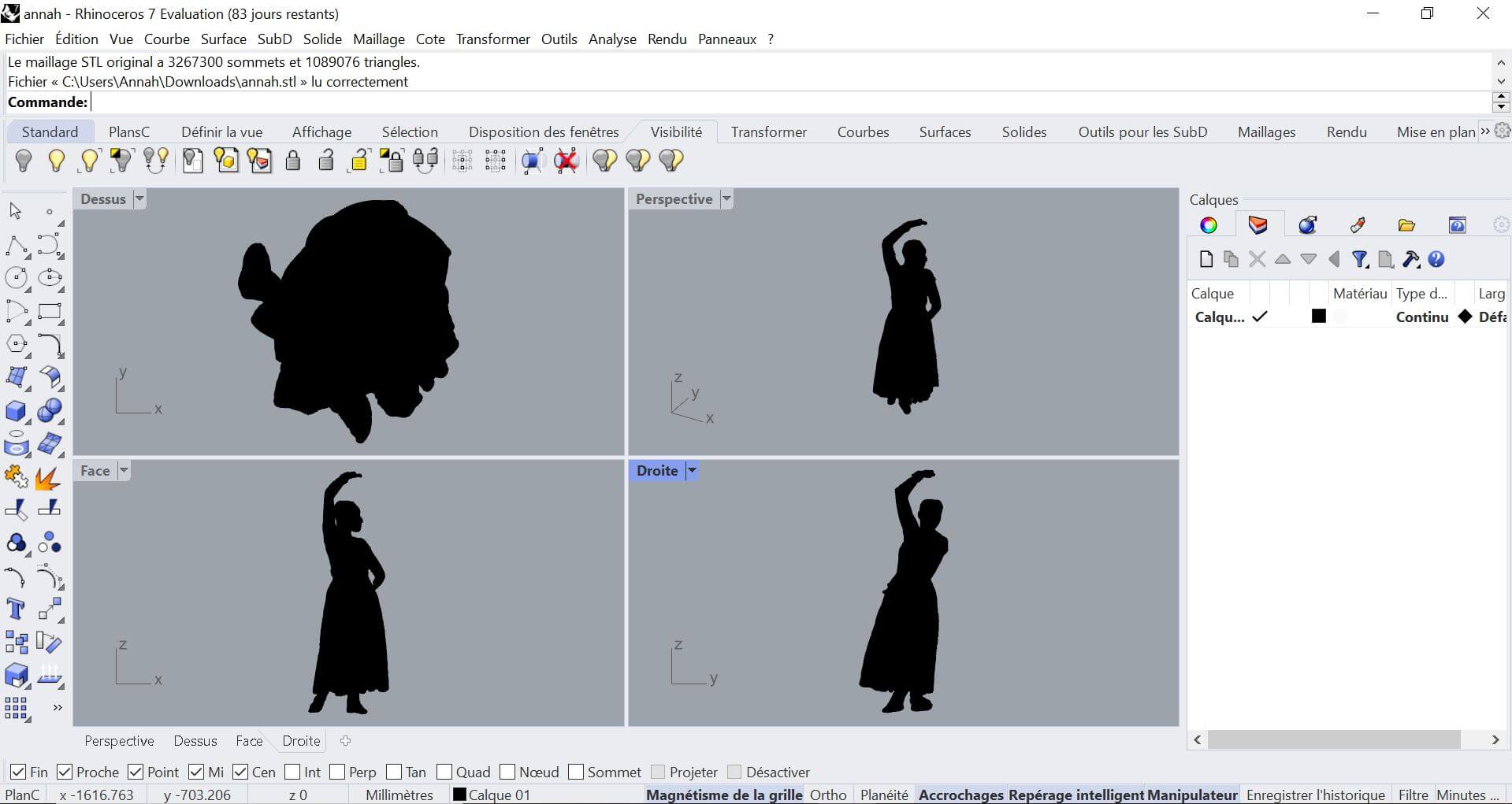
Once I obtained a human model with the features I wanted on MakeHuman, I exported it as a .stl file into Rhinoceros3D. The result in Rhinoceros3D is a mesh structure, which does not exactly work like a solid object. Thus, it must be specified to the software by mentioning "Mesh" in the command.
BooleanDifference    -->    MeshBooleanDifference
Trim                 -->    MeshTrim
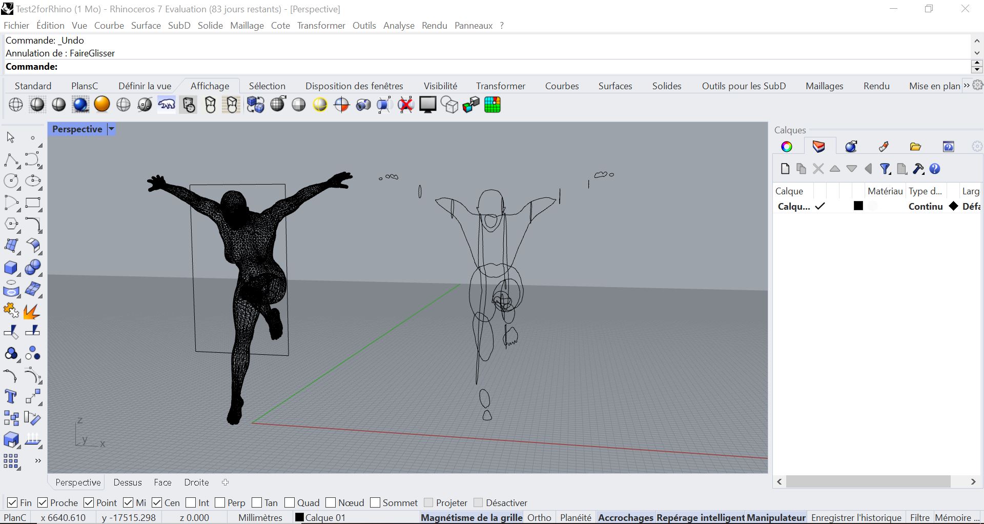
To cut cardboard or wood in the laser cutter, one has to take into account the maximum capacity of the machine and be very careful with the scaling. I wanted to make a 1:1 scale mannequin so I drew a cube of 1000 x 600 x 600 mm to know how to trim the figure in a way that the laser cutter would be able to process. As I said in the Research paragraph, I was really inspired by the void, the polychromy and the transmission of emotions. For the emotions, I chose the pose as explained before. For the polchromy and the void, I decided to split my mannequin into two parts that would be made out of different textures and techniques. I decided to use a cardboard folded pattern for the bottom of the mannequin because I love the geometry it gives to the figure and then use a waffle strcture for the top. This way, I would have void and polychromy. Splitting my mannequin into two also allowed me to make it bigger than if I had used only one material since they must be cut on separate boards of 600 x 1000 mm in the laser cutter.
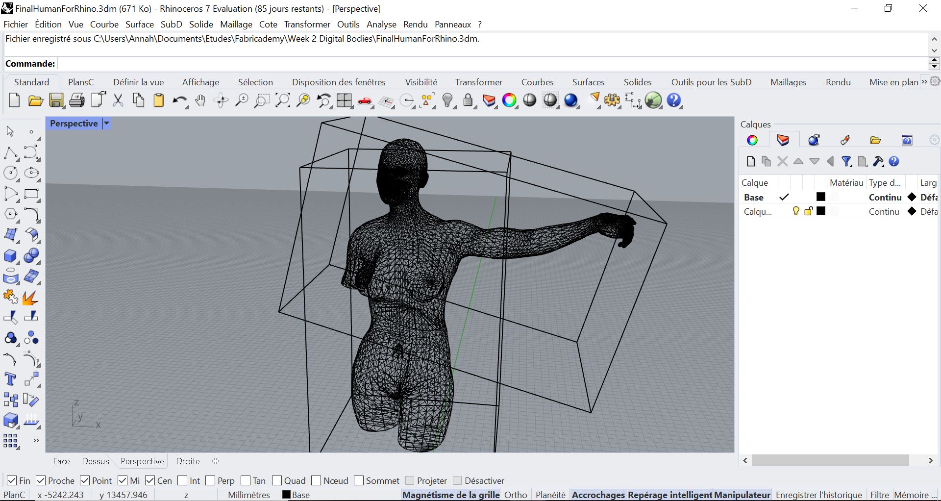
As I said before, I really like the void in the structures and think the mesh structures in Rhino look very nice just the way they are!
To export the two different parts of the mannequin, I had to make sure I had closed meshes and exported each part in a different .stl file.
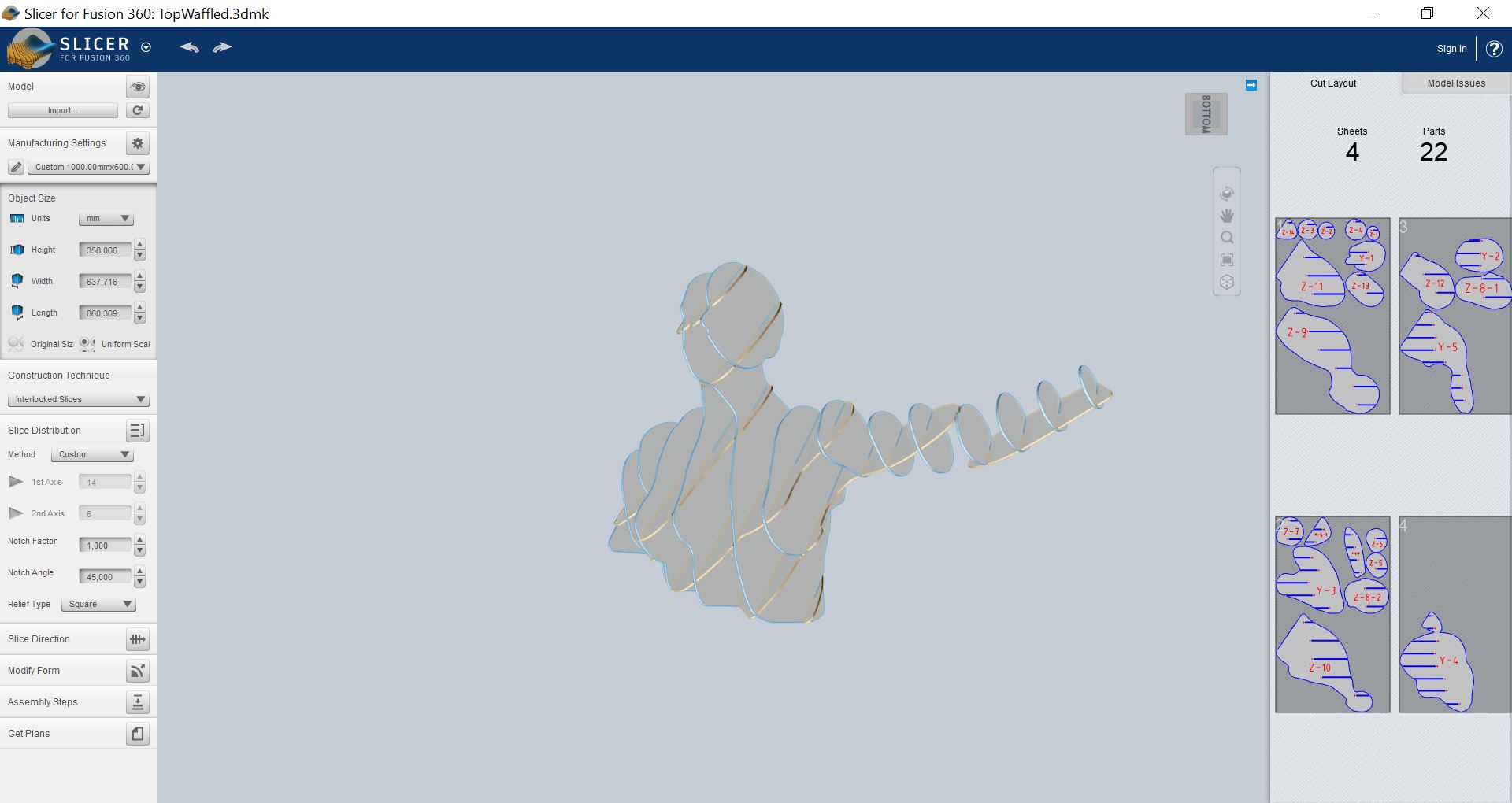
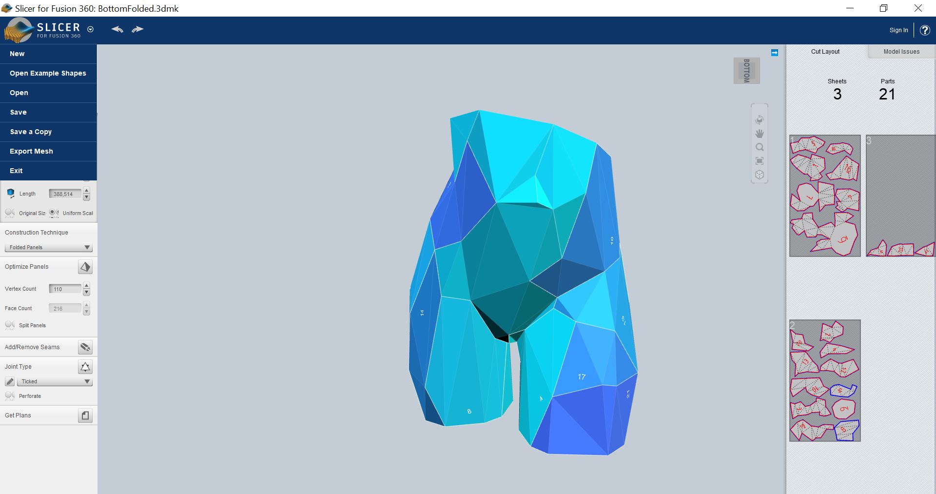
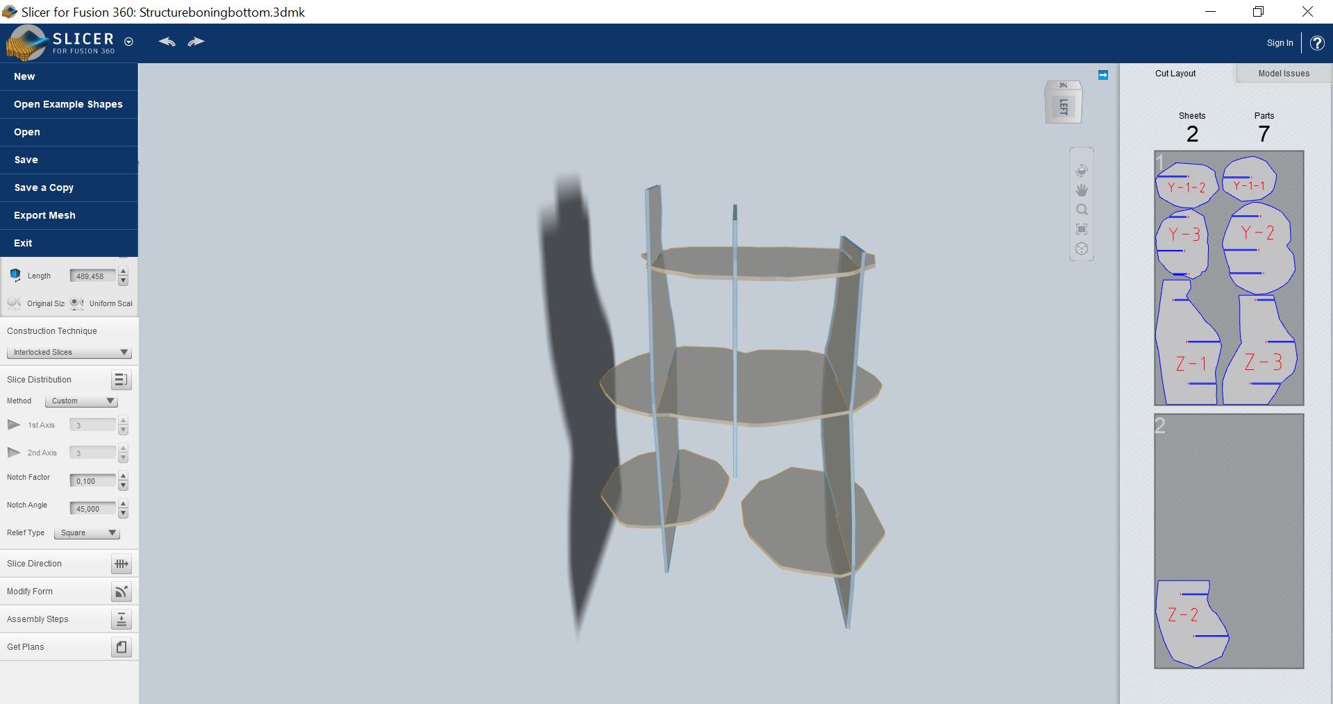
VI-Slicer for Fusion
Slicer for Fusion is a software turning 3D models into patterns cuttable in a laser cutter. The different patterns available are stacked slices, interlocked slices, radial slices or folded pannels. Before using it, I made sure to put the information of the laser cutter (size and thickness of the material), verify the scale applied was the same as the one I chose on Rhinoceros3D and only then could apply the desired pattern to the mannequin. I chose folded pannels for the bottom and modified the pattern to avoid having too big pieces. As I said before, I really like the void in the human figures and wanted to make the mannequin hollow to only have the outline of the body. Unfortunately, I could not because of assembly reasons: assembling waffled structures with two slits is impossible. To make it easier, I chose to keep it full, changed the number and orientation of the pannels and added a bit of shrinkwarp which resulted in a less detailed and thicker figure.
After reaching a waffle structure I liked, I exported the plan as a PDF file and uploaded it on Rhino3D for some optimization of the material utilization.
For the bottom, I wanted to do a folded structure so I used this option on the software. I ended up with 21 different pieces which is way too much and caused me trouble as you will see in further paragraphs...
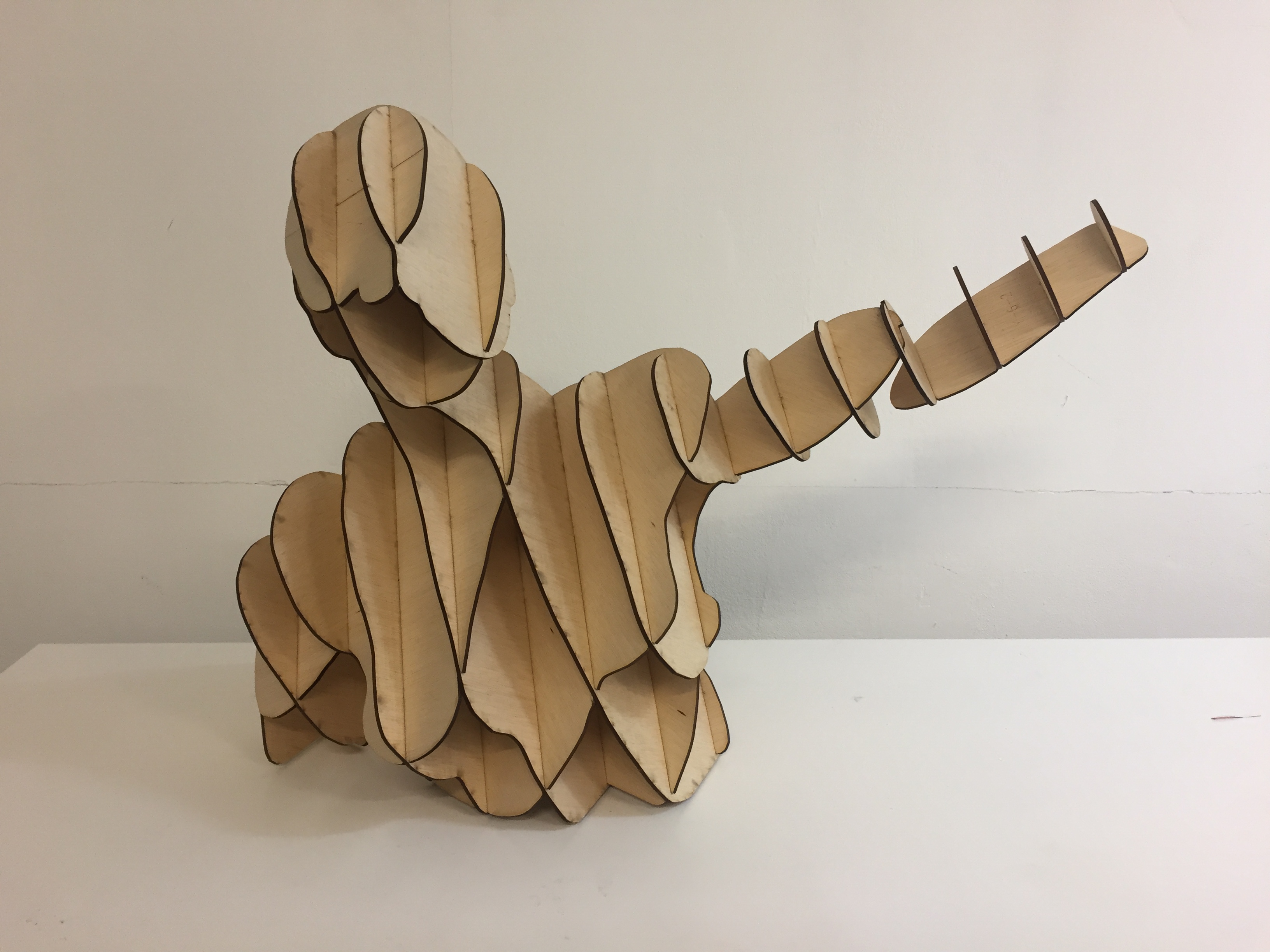
Here is a 3D model of the final mannequin with the waffle top and folded bottom assembled:
Under these link are the cutting files of the waffle top and the folded bottom.
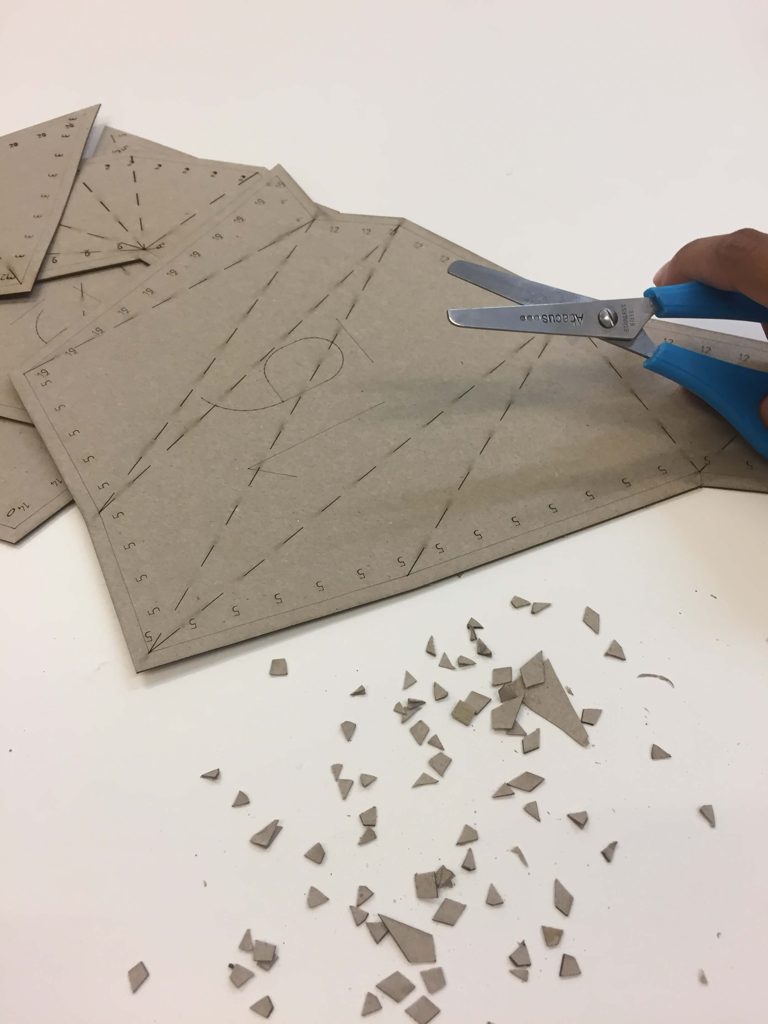
VII-Laser cutting
Josep explained us how to use the laser cutter and here are the main recommandations:
- Focus the laser manually with the little plastic tool
- Make sure the board you are cutting is flat and not curved. If it is, make sure it is curved on the edges and not in the middle and fix it with paper tape (no fumes).
- Save files to be cut as Rhino5 files.
- 3 different operations: cutting (make sure you first cut the inner parts), engrave (same operation as cutting, just with different power), raster (pixel burnt 1 by 1, can be used to do grayscales, drawings etc).
- _Hatch command: fills in black (for raster)
- Make sure your folder only has joined lines and no double lines (_SelDupl allows to identify double lines), if not the laser cutting is going to take some extra time.
- Refer to the color code to set the order of the operations.
- Command _print to send the job to the printer
- If you have vector and raster elements in your document, use “vector”.
- Make sure to use the following parameters : display color, scale 1:1, top view
Once we have all these parameters set, we can start printing. The printer uses the software "Trotec" to work. We can set different parameters in the cutter: the freqency, the power and the speed. It is better to set a low frequency for organic material to avoid flames (1000 Hz) and a higher one for plastic for a cleaner output as it will allow the edges to melt and be softer (25000). The power and the speed are related, and it is up to us to find the good balance experimentally. To engrave, a high speed is usually used. When we are ready to cut, before pressing the print button, we should one last time make sure that: * The air extraction is turned on (extraction of the fumes). * The parameters are set. * The laser is focused.
For the cutting of the wood pannels, I used 4mm thick pannels and cut them with a power of 75, speed of 0,5 and frequency of 1000 Hz. For the engraving, I switched the power to 85 and the speed to 100. For the paper, I used a power of 30, a speed of 1 and a frequency of 1000 Hz. The engraving was made with a power of 80 and a speed of 100.
VIII-Assembly and final result
a-Waffle top
After cutting, I started the assembly of the waffle structre. I realized for the next time that it would have been better to use a lower offset for the slots because I genuinely had to use a hammer to make it interlock. I had another problem with the arms: I did not realize that the slots of one piece were too small to interlock and ended up with two separate pieces of arm... I thus decided to redraw the Z-4 piece manually in Rhino by adding a new slot.
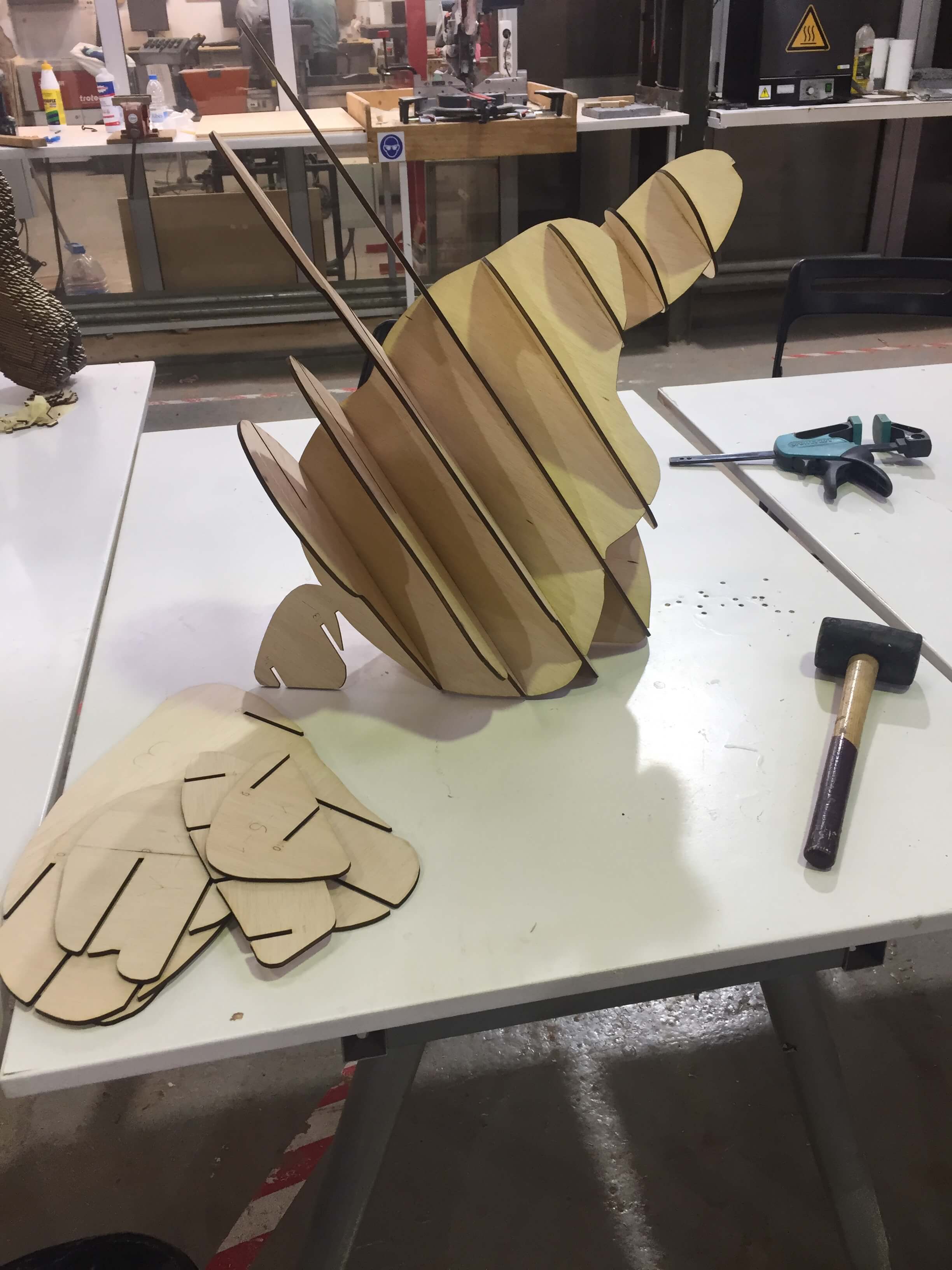
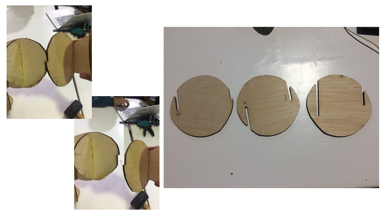
I had to draw the piece twice because I did not consider the slot had to be deeper since there was no complementary slot on the other piece. The last piece (right piece on the right picture) I designed was suitable for the mannequin and with a little bit of cheating (I added a bit of wood glue to maintain it in place), the arm could successfully be assembled.
b-Folded Bottom
This is the part things started to go south. First, I wanted to do the folded structure in cardboard, but I did not consider that it would be fluted cardboard. The fluting goes in one single direction, but the folds go in different directions, making some of the folds difficult to bend. Moreover, I wanted to assemble each folded pannel using diamond structures that were way too small to be maintained together. That is why I decided to use thick paper instead of cardboard and tried different techniques to assemble the different panels together: diamonds, rivets, sewing, laced... For aestetic purposes, I chose to use the plans made for sewing and use the sewing allowance as tabs to finally glue the pannels together.
Since the bottom structure is supposed to support the wooden structre (heavy), I also decided (with the help of Anastasia and Josep) to put a wooden structure inside the folded structure (I exported the folded structure as a .stl folder, reopened it in slicer and then did a waffle structure out of it. Once I put it back into Rhino3D, I scaled the cutting board 0,996 for the wooden waffled structure to fit inside the cardboard folded structure).
BUT I had troubles gluing the paper panels together because :
- I had way too many pannels and should absolutely have had played more with the "Add/Remove seams” option in order to reduce the amount of pieces to the minimum.
- for some reason, the glue did not glue fast enough the paper I chose. Considering I had 21 pannels with different shapes, a small tab to assemble them and a 3D structure, this seemed like an impossible task. I did not want to change the material or the technique either because it was not the aesthetic I had in mind and I did not have time to start over. Soooo I consider this first Fabricademy assignement being quite a fail…
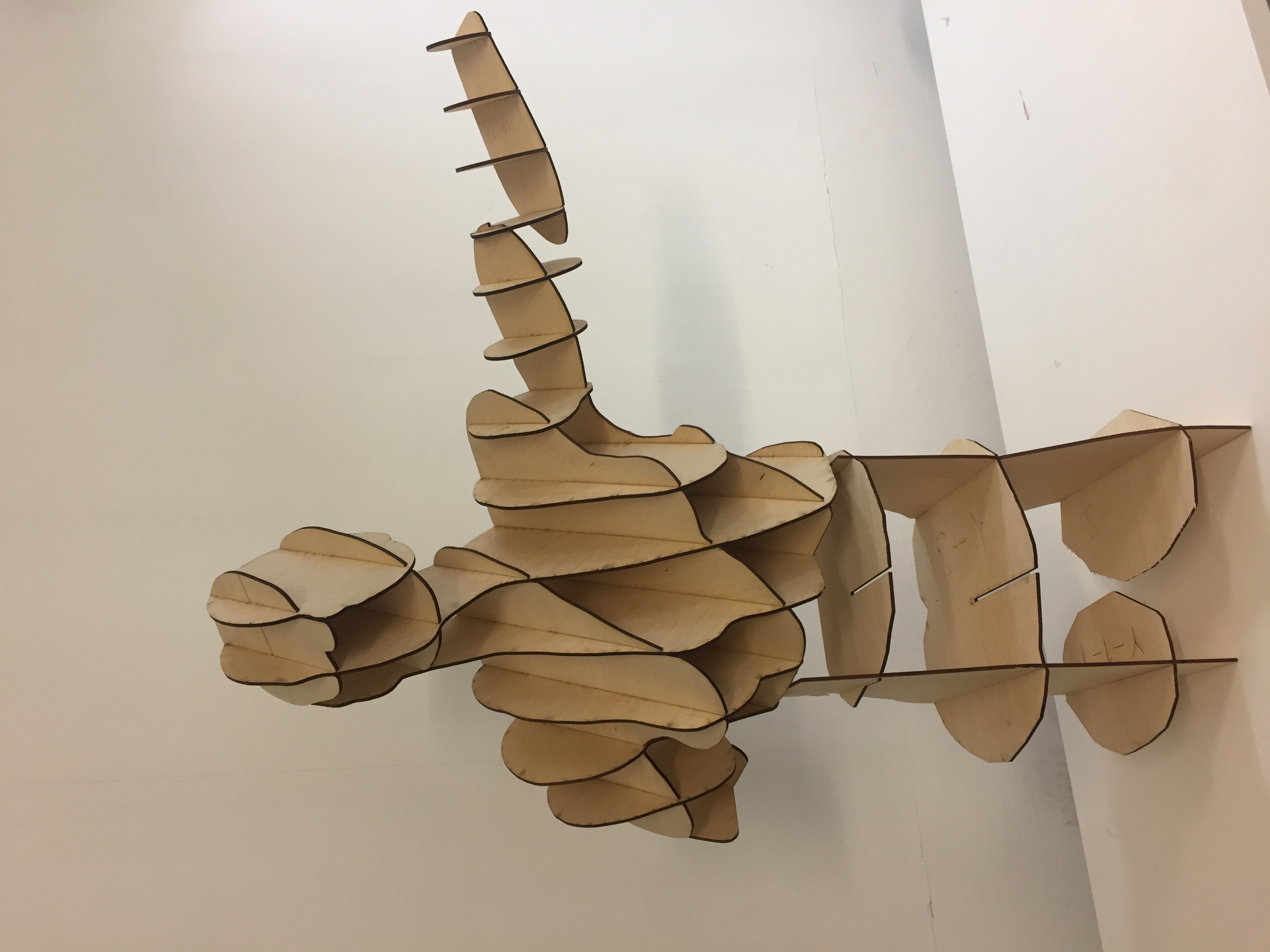
IX-Update
The next week(s), I bought instantaneous glue and retried to assemble the pannels because I do not accept failing. This worked better but is was still not strong enough to support the whole structure (I am only talking about the bottom here). I also bumped into another problem: the tabs are 5mm long and the boning structure was only rescaled to 0,996 so it is still too big and does not fit inside the paper structure... After numerous trials, I finally accepted that my mannequin is never going to stand on its two legs and will only be a waffled top... It could still stand on the reinforcement waffle structure to have an idea of how it should have looked but it is extremely unstable. I just accepted that for a first week, the waffle top (that looks great) would be enough!