13. Skin Electronics
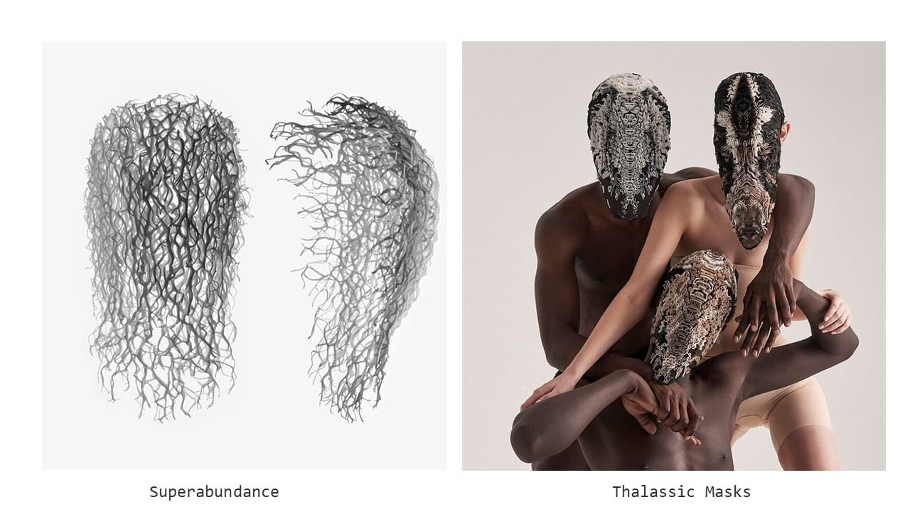
This week, we had a lecture of Filippo Nassetti who developped 3D printed masks. His work was very inspiring and I especially liked the masks that had layers of different colors 3D printed on fabric.
Skin is a shield, a separation betweed the inner an the outer self, but also our sensor and the mean by which we appear. However, our envelope is not only composed by skin, but also by hair or nails. These interfaces can be customized and augmented for aesthetic and functionnal purposes (tatoos, nail polish, makeup, clothes, dyes, cutting).
Katia Vega, who led this week's lecture and works at a Human computer interactions lab, created the brand Beauty technology making unnoticable wearable devices that camouflage electronics within cosmectics and conceal interactions by using human behaviors. She also studied our gestures to use as sensors or triggers. There are different types of gestures: the informative ones (body language) and communicative gestures (manual or non manual), but also the gestures we make for interacting with objects. She named this technique "the conscious use of unconscious behaviors".
Assignement
- Document the concept, sketches, references also to artistic and scientific publications
- Design a skin circuit: build your own version of the “Skin masquerade party” project or build your own version of the “Twinkle Nails” project
- Document the project and included all source files and all materials used
- Make a video with your skin electronic working
- Make a performance of your project functioning
I-Ideation process and inspiration
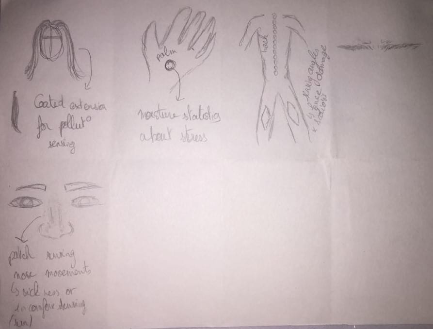
During the lecture, Katia made us do an exercise consisting in folding a paper in 8 and drawing an idea every other minute. I found this technique very interesting and efficient when you are lacking inspiration because the time limit forces you to come out with some ideas. I could not finish it but here are the ideas I came out with:
 After this execise, I took a little bit more time to do sketches of the various ideas I had. Of course, I always want to do things too big and here is my first idea: I wanted to make a harness covered in feathers for carnival, that would make different movements depending on the stimulus. I did not define the stimulus yet, but the different movements would be static in down position, shaking in down position, static in up position and shaking in up position.
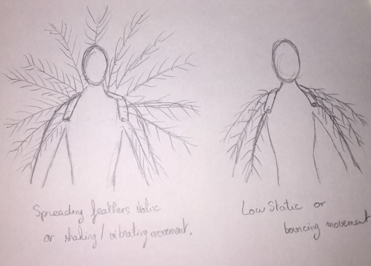
I was inspired by peacocks, carnival outfits and by this project from Cameron Hughes, and engineer and designer who made a headset with moving feathers.

Of course, this project would involve designing a harness on rhino, finding out a way to embedd feathers in it, finding a way to move the feathers the way I want with gears, finding the appropriate motors, a way to encode the different movements... This project was way too ambitious for a single week and I knew it sooo I decided to swich and go for another less complicated one.
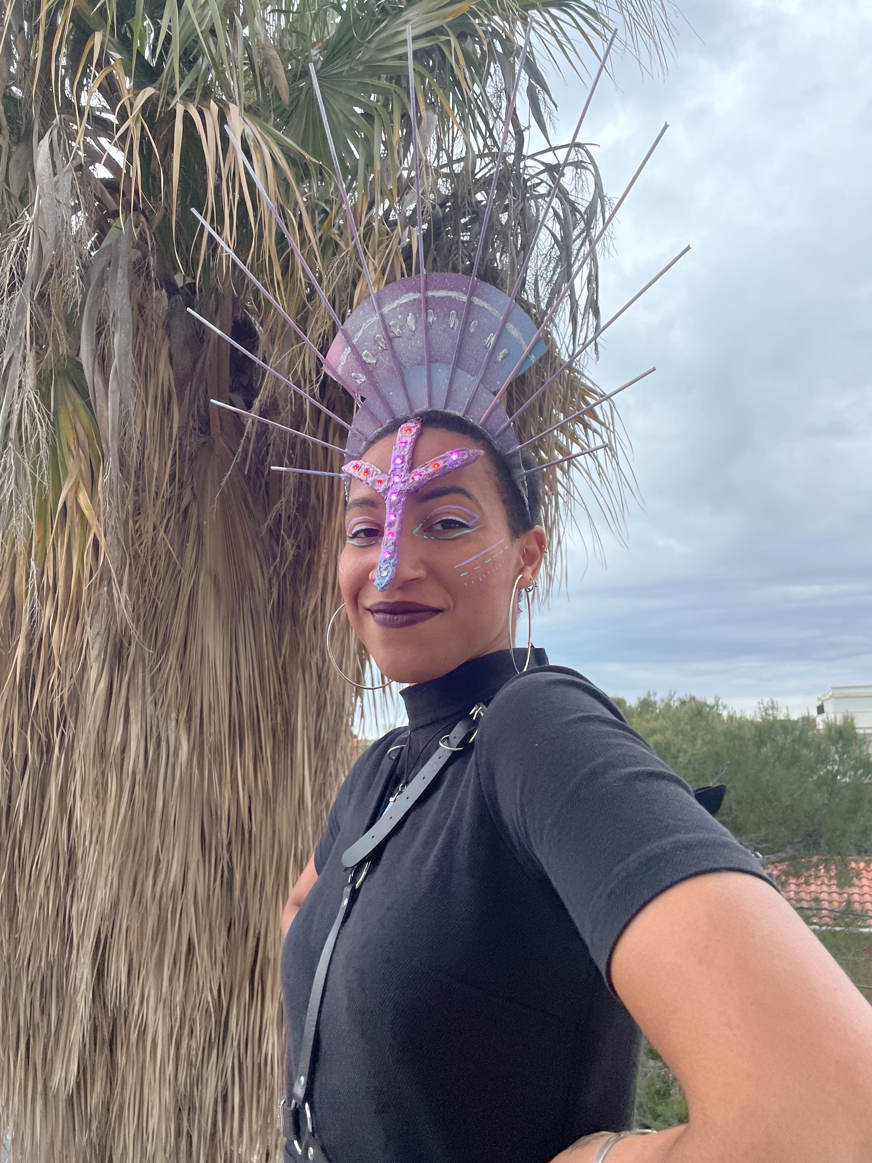
Keeping the idea of carnival and masks, I got some inspiration from traditional African masks and face paintings. I decided to replace the dots by neopixels and would see how I want to program it afterwards.

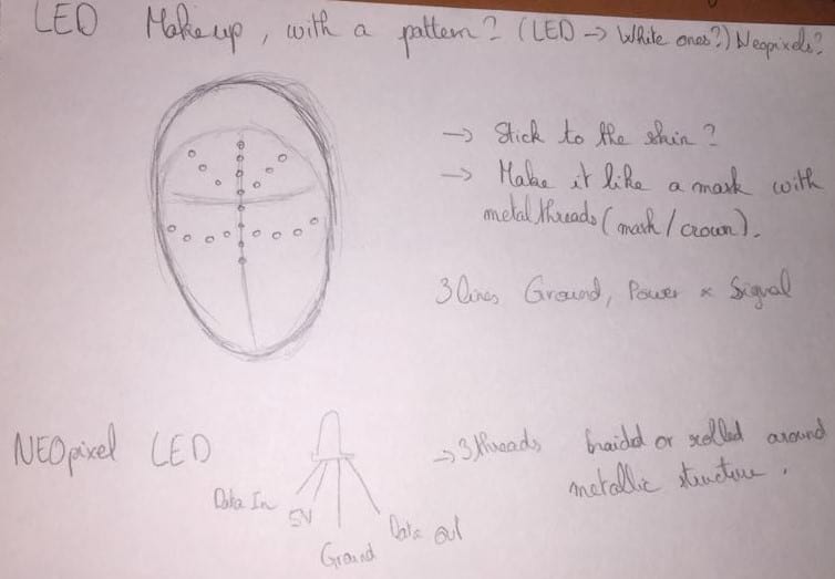
II-Neopixels and circuit.
My next step, after having the idea, was to code the neopixels. To begin with, I decided to code the neopixels on Arduino and after this would work, I would code them for ATtiny. I wanted my mask to have soothing light fades in the purple-pink tones. I had some troubles finding out how to encode it but after some research, some understanding of the neopixels and modyfing some code found on this forum. I came out with a code calling four functions fading in from blue to purple (colors are changing and the neopixels are getting brighter at the same time), then fading out from purple to red. And then, in order to have a smooth transition between the two functions, I added a fade-in from red to purple and a fade-out from purple to blue. Then the loop can go smooth!
Arduino fading neopixels code.
#include <Adafruit_NeoPixel.h>

#define PIN   1
#define LED_COUNT   9

// Parameter 1 = number of pixels in strip
// Parameter 2 = Arduino pin number (most are valid)
// Parameter 3 = pixel type flags, add together as needed:
//   NEO_KHZ800  800 KHz bitstream (most NeoPixel products w/WS2812 LEDs)
//   NEO_KHZ400  400 KHz (classic 'v1' (not v2) FLORA pixels, WS2811 drivers)
//   NEO_GRB     Pixels are wired for GRB bitstream (most NeoPixel products)
//   NEO_RGB     Pixels are wired for RGB bitstream (v1 FLORA pixels, not v2)
Adafruit_NeoPixel strip = Adafruit_NeoPixel(LED_COUNT, PIN, NEO_GRB + NEO_KHZ800);

// IMPORTANT: To reduce NeoPixel burnout risk, add 1000 uF capacitor across
// pixel power leads, add 300 - 500 Ohm resistor on first pixel's data input
// and minimize distance between Arduino and first pixel. Avoid connecting
// on a live circuit... if you must, connect GND first.

void setup() {
  strip.begin();
  strip.show(); // initialize all pixels to "off"
}

void loop() {
    brighten1();
    darken1();
    brighten2();
    darken2();
}


void brighten1() {
  uint16_t i, j;

  for (j = 20; j < 200; j++) {
    for (i = 0; i < strip.numPixels(); i++) {
      strip.setPixelColor(i, j + 10, 0, 200);
    }
    strip.show();
    delay(20);
  }
}


void darken1() {
  uint16_t i, j;

  for (j = 200; j > 20; j--) {
    for (i = 0; i < strip.numPixels(); i++) {
      strip.setPixelColor(i, 200, 0, j + 20);
    }
    strip.show();
    delay(20);
  }
}

void brighten2() {
  uint16_t i, j;

  for (j = 20; j < 200; j++) {
    for (i = 0; i < strip.numPixels(); i++) {
      strip.setPixelColor(i, 200, 0, j + 10);
    }
    strip.show();
    delay(20);
  }
}


void darken2() {
  uint16_t i, j;

  for (j = 200; j > 20; j--) {

    for (i = 0; i < strip.numPixels(); i++) {
      strip.setPixelColor(i, j + 10, 0, 200);
    }
    strip.show();
    delay(20);
  }
}
I chose 9 as the number of neopixels because it was the biggest length of Neopixels I would use.
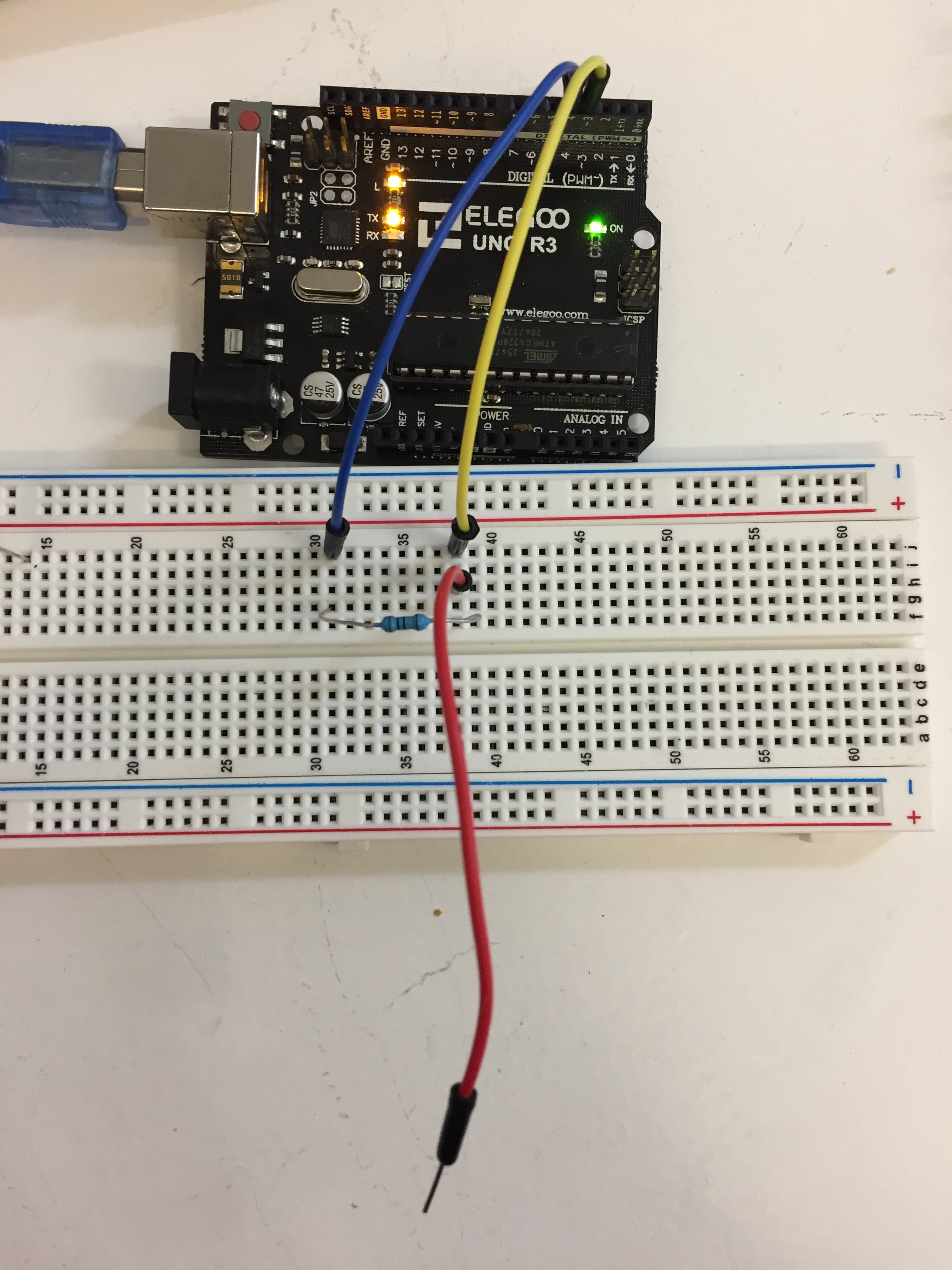
Then, I wanted to make the mask a bit fancier so I tried adding a capacitive sensor to the circuit. A capacitive sensor is a very easy circuit to make as we only need a resistor and 3 cables to make it. Basically, the uncovered tip of the wire acts like a capacitor: if something conductive goes next to it, the current will "see a way out" through this wire and will take longer time to go from pin 3 to pin 4. This step was pretty easy to make as I already had this code and circuit from the lecture with Emma.
Arduino capacitive sensor code.
#include <CapacitiveSensor.h>
CapacitiveSensor cs = CapacitiveSensor (4,3); // 10M resistor between pins 4 & 3, pin 3 is sensor pin, add a wire and or foil if desired
//int led_pin = 7 ;


void setup() {
  // initialize input and output pins
//  pinMode (led_pin, OUTPUT);
  Serial.begin(9600);
}

void loop() {

  long lecture = cs.capacitiveSensor (30);

  Serial.println(lecture);

  if (lecture > 300 ){
  digitalWrite (led_pin, HIGH);
  }
  else {
    digitalWrite (led_pin, LOW);
  }
  delay (200);

}
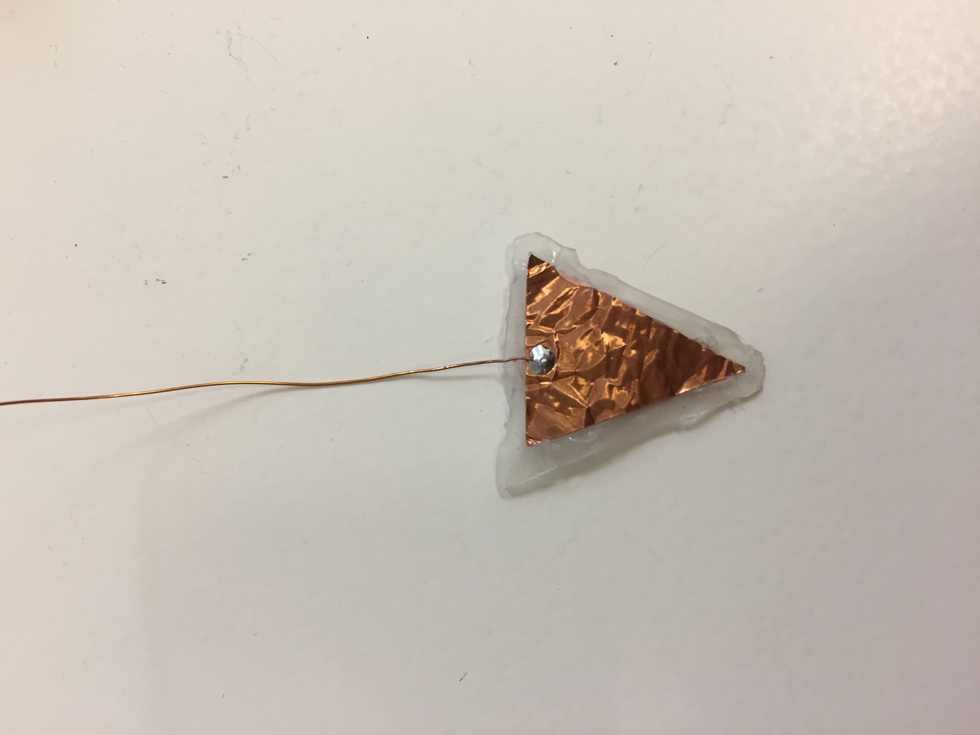
I made a soft capacitive sensor using a copper wire and copper tape. It was meant to be stuck to the the nape of the neck, aka already on the skin. I decided to separate the copper tape from the skin with hot glue so that it would still be sensitive to a pressiure from my fingers.
After making it function, I determined the threshold of the sensor would be 250 after viewing the serial monitor values. In the program, I decided the neopixels would be following the fade program when the sensor is not triggered and would follow the rainbow function I found in Example > Adafruit NeoPixels > standardtest. This is the final code I came up with.
Arduino fading neopixels code.
#include <CapacitiveSensor.h>
CapacitiveSensor cs = CapacitiveSensor (4, 3); // 10M resistor between pins 4 & 3, pin 3 is sensor pin, add a wire and or foil if desired
#include <Adafruit_NeoPixel.h>

#define PIN   1
#define LED_COUNT   9

// Parameter 1 = number of pixels in strip
// Parameter 2 = Arduino pin number (most are valid)
// Parameter 3 = pixel type flags, add together as needed:
//   NEO_KHZ800  800 KHz bitstream (most NeoPixel products w/WS2812 LEDs)
//   NEO_KHZ400  400 KHz (classic 'v1' (not v2) FLORA pixels, WS2811 drivers)
//   NEO_GRB     Pixels are wired for GRB bitstream (most NeoPixel products)
//   NEO_RGB     Pixels are wired for RGB bitstream (v1 FLORA pixels, not v2)
Adafruit_NeoPixel strip = Adafruit_NeoPixel(LED_COUNT, PIN, NEO_GRB + NEO_KHZ800);

// IMPORTANT: To reduce NeoPixel burnout risk, add 1000 uF capacitor across
// pixel power leads, add 300 - 500 Ohm resistor on first pixel's data input
// and minimize distance between Arduino and first pixel. Avoid connecting
// on a live circuit... if you must, connect GND first.

void setup() {
  strip.begin();
  strip.show(); // initialize all pixels to "off"
  Serial.begin(9600);
}

void loop() {

  long lecture = cs.capacitiveSensor (30);
  Serial.println(lecture);

  if (lecture > 250 ) {
    rainbow(10);
    strip.fill(strip.Color(255, 255, 255), 0, 9);
  }
  else {
    brighten1();
    darken1();
    brighten2();
    darken2();
  }
}


void brighten1() {
  uint16_t i, j;

  for (j = 20; j < 200; j++) {
    long lecture = cs.capacitiveSensor (30);
    Serial.println(lecture);

    if (lecture > 250 ) {
      break;
    }
    for (i = 0; i < strip.numPixels(); i++) {
      strip.setPixelColor(i, j + 10, 0, 200);
    }
    strip.show();
    delay(20);
  }
}


void darken1() {
  uint16_t i, j;

  for (j = 200; j > 20; j--) {
    long lecture = cs.capacitiveSensor (30);
    Serial.println(lecture);

    if (lecture > 250 ) {
      break;
    }
    for (i = 0; i < strip.numPixels(); i++) {
      strip.setPixelColor(i, 200, 0, j + 20);
    }
    strip.show();
    delay(20);
  }
}

void brighten2() {
  uint16_t i, j;

  for (j = 20; j < 200; j++) {
    long lecture = cs.capacitiveSensor (30);
    Serial.println(lecture);

    if (lecture > 250 ) {
      break;
    }
    for (i = 0; i < strip.numPixels(); i++) {
      strip.setPixelColor(i, 200, 0, j + 10);
    }
    strip.show();
    delay(20);
  }
}


void darken2() {
  uint16_t i, j;

  for (j = 200; j > 20; j--) {
    long lecture = cs.capacitiveSensor (30);
    Serial.println(lecture);

    if (lecture > 250 ) {
      break;
    }
    for (i = 0; i < strip.numPixels(); i++) {
      strip.setPixelColor(i, j + 10, 0, 200);
    }
    strip.show();
    delay(20);
  }
}

void rainbow(int wait) {
  // Hue of first pixel runs 5 complete loops through the color wheel.
  // Color wheel has a range of 65536 but it's OK if we roll over, so
  // just count from 0 to 5*65536. Adding 256 to firstPixelHue each time
  // means we'll make 5*65536/256 = 1280 passes through this outer loop:
  for (long firstPixelHue = 0; firstPixelHue < 5 * 65536; firstPixelHue += 256) {
    for (int i = 0; i < strip.numPixels(); i++) {
      // For each pixel in strip...
      // Offset pixel hue by an amount to make one full revolution of the
      // color wheel (range of 65536) along the length of the strip
      // (strip.numPixels() steps):
      int pixelHue = firstPixelHue + (i * 65536L / strip.numPixels());
      // strip.ColorHSV() can take 1 or 3 arguments: a hue (0 to 65535) or
      // optionally add saturation and value (brightness) (each 0 to 255).
      // Here we're using just the single-argument hue variant. The result
      // is passed through strip.gamma32() to provide 'truer' colors
      // before assigning to each pixel:
      strip.setPixelColor(i, strip.gamma32(strip.ColorHSV(pixelHue)));
    }
    strip.show(); // Update strip with new contents
    delay(wait);  // Pause for a moment
  }
}
This code is optimized with the addition of another lecture of the sensor during the fade-in and fade-out voids so that the frequency of the lecture of the sensor is higher. In order to see if the Neopixels would work with a battery, I did not use the 5V pin but I used the 3.3 V.
III-Programming ATtiny
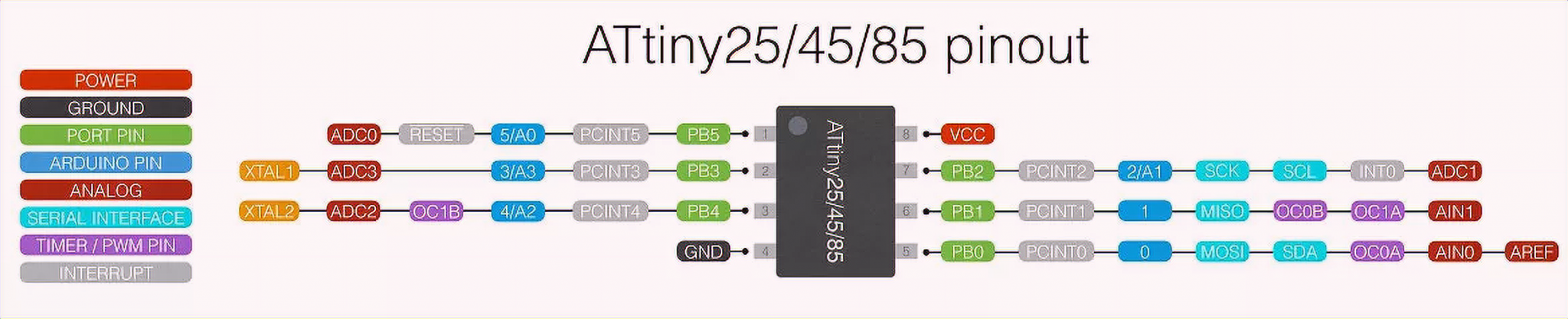
ATtiny is a microcontroller, acting as a tiny Arduino. It has less capacity and takes in less functions than an Arduino board but has the huge advantage to be transportable and embeddable in wearables. The ATtiny we are using is ATtiny 85 and has 8 pins. It is better not to use pin 1 because it is also the one of reset and can sometimes generate problems.
A breakout board allows prototyping by creating easier connections with the legs of the ATtiny. More documentation on sensors, actuators and microcontrolers can be found here.
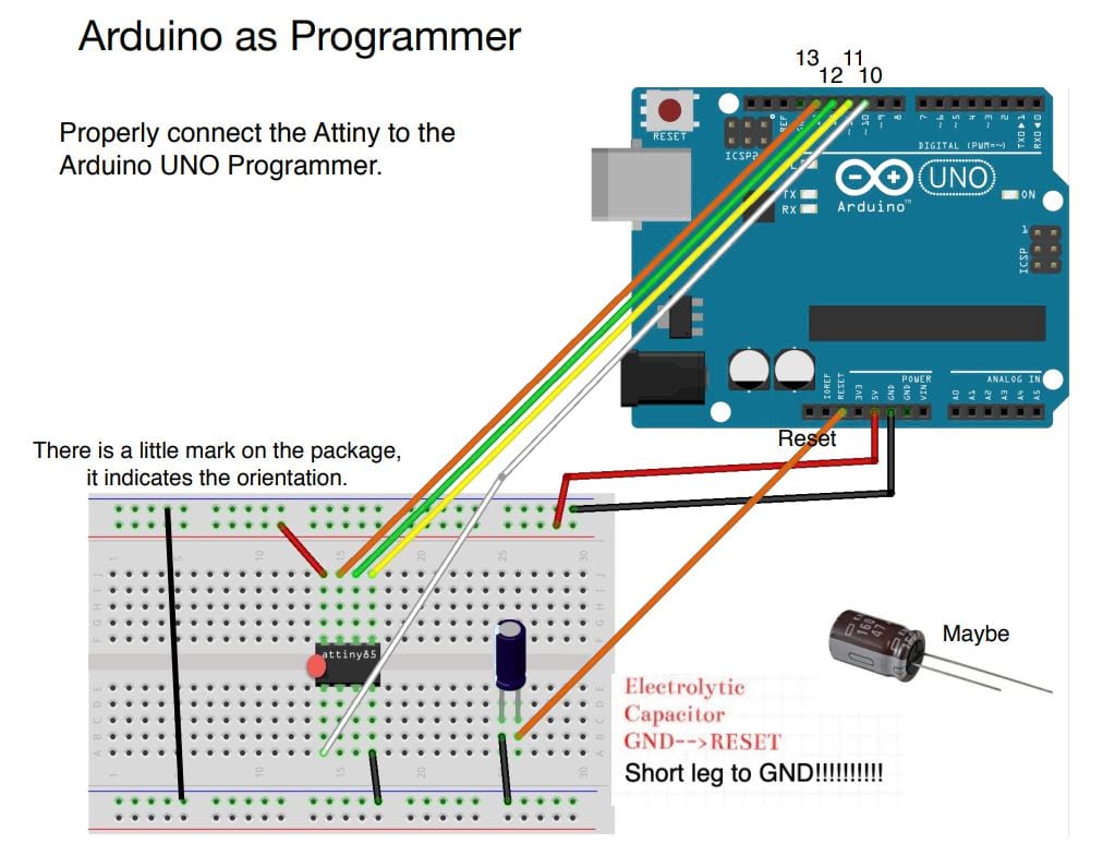
Before programming an ATtiny, if you are using the Tiny AVR programmer, you need to install Zadig to make it recognizable by your computer (tutorial here). If you don't have a Tiny AVR programmer, you can still program the ATtiny with the Arduino following these instructions. You will need a certain setup to use arduino as a programmer for ATtiny, and a program which is already loaded in the Arduino.exe in Files > Examples > Arduino as ISP.
Open arduino interface. In tools, you need to select a new board. For that, you need to open preferences and add an additional board using the following link: https://raw.githubusercontent.com/damellis/attiny/ide-1.6.x-boards-manager/package_damellis_attiny_index.json .
- Then in Tools > Boards > Boards manager, search for "ATtiny" and install it.
- Then, you can select the ATtiny we are going to use un Tools > Boards > ATtiny Microcontrollers > ATtiny 84.
- You also need to check the processor in Tools > Processor > ATtiny 85 and define the clock in Tools > Clock > Internal 8 MHz. The clock is the frequency at which we define the speed of execution of instruction, which depending on the setting, consumes more or less power from the battery. -The programmer needs to be set to Tools > Programmer > USBtinyISP.
- When everything is set, press Tools > Burn Bootloader. To swich back to Arduino, you only need to change the board again and the programmer. Here is the connections that should be made to use Arduiono as an ATtiny Programmer.
To recieve information from the ATtiny board, we need a FTDI cable or chip.
I adapted the arduino code to the ATtiny by simply adding these lines to the beginning of the code and deleting the lines involving Serial.begin or Serial.println. All the other functions used were supported by ATtiny. I also used the same pins: 3 and 4 for the capacitive sensor and 1 for the NeoPixels.
#ifdef __AVR__
 #include <avr/power.h> // Required for 16 MHz Adafruit Trinket
#endif //This is required when using an ATtiny.
For the power source, it is important to make sure to have enough amperage with your battery for all the electronics you want to use. The capacity of the battery per hour is given in the datasheet (rechargable 3.7v LiPo battery: 600 mA/h) and the consumption of the electronics is also given in the datasheet. I, however, did not make any of these calculations but as you can see on the video, the 3.7v LiPo battery works since it already worked with the 3.3V pin of the Arduino.
IV-Creating the mask
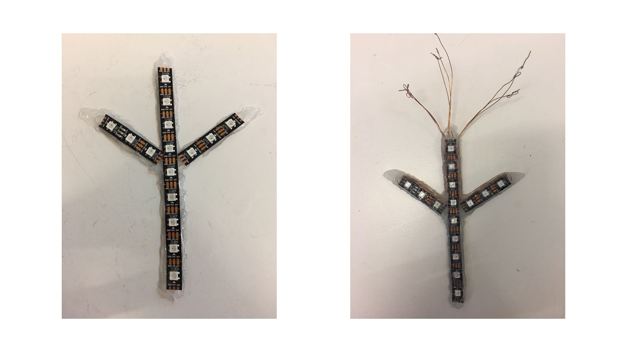
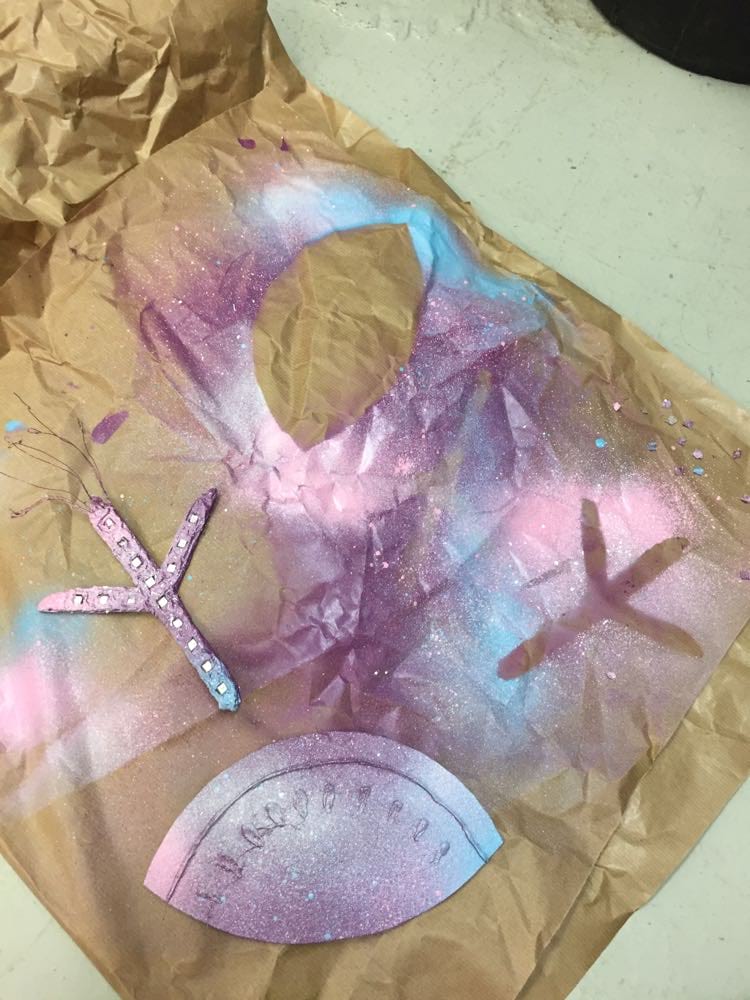
To make the mask, I had to be creative. Since I had not much time left, I decided I would assemble the Neopixels together using hot glue. I first drew the shape I wanted, covered the drawing with baking paper and finally drew the shape and embedded the NeoPixels with the hot glue. I soldered the ground, command and 5V pins with thin copper wires. Then I added a layer of hot glue on them so that the would follow the shape of the mask.
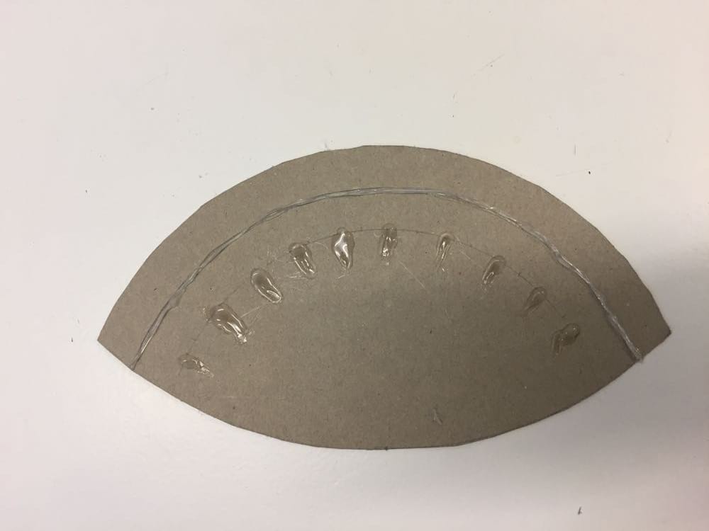
I also needed to find a way to hide the electronics (ATtiny and battery) so I added a carboard unit to the top of the mask, that would have decorative and functial purposes. For a nicer look, I added some texture to it with some hot glue dots that I would later paint in white.
The overall look was kind of busted looking so I decided to paint it (as Lena said, "spray paint is so forgiving") and it turned out much better!
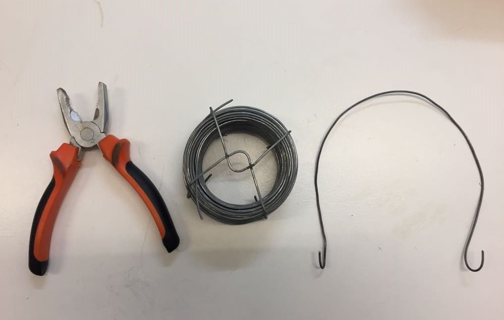
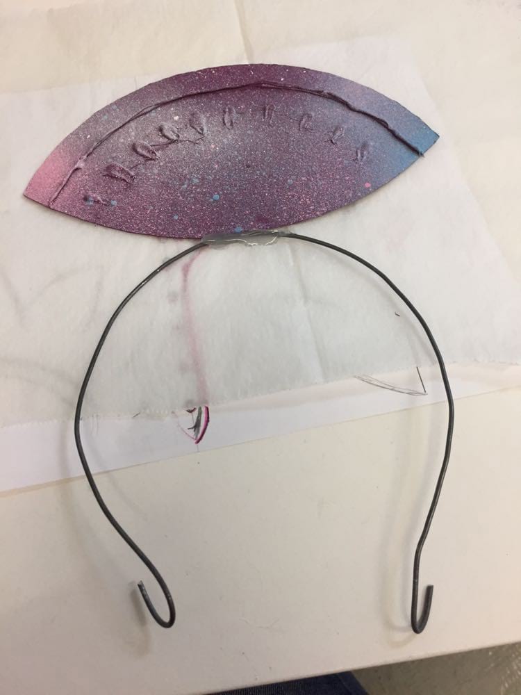
I fixed the cardboard piece to a bended thick metal wire that acts like a headband.
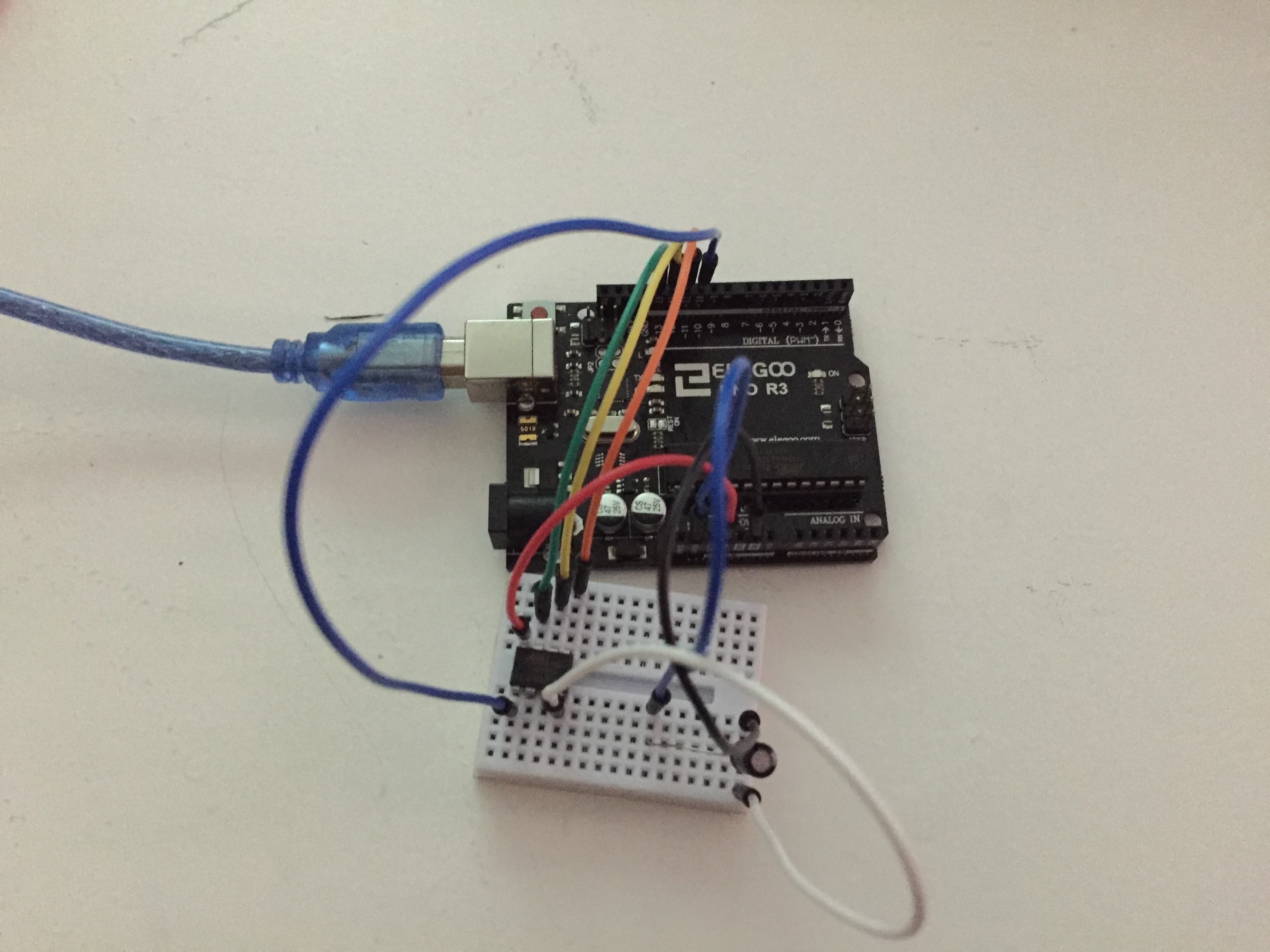
I assembled the circuit and used a breakout board for easier connection to the pins. The pins of the breakout board are not the same as the ones in the ATtiny so I had to check with the multimeter if I had done the connections right before soldering.
When I tried to assemble the circuit and make it work outside of the breadboard, I had a problem and the LEDs started to light up chaotically and the left branch did not light up at all. I think there was some misconnection in the circuit I made for the chaotic lighting because when I made it with aligator pines, the middle an right braches worked again.
I thus had to make all the soft connections again and really struggled to make the circuit work out of the breadboard. I eventually got how to do it after multiple attemps. But I decided to change the code and get rid of the capacitive sensor since everything was already so fragile and working poorly. I later learned that a capacitive sensor had to work with a ground but I did not know that when doing the prototype so could not checked if it would have worked.
Arduino fading neopixels code.
#include <Adafruit_NeoPixel.h>

#ifdef __AVR__
 #include <avr/power.h> // Required for 16 MHz Adafruit Trinket
#endif //This is required when using an ATtiny.

#define PIN   1
#define LED_COUNT   9

// Parameter 1 = number of pixels in strip
// Parameter 2 = Arduino pin number (most are valid)
// Parameter 3 = pixel type flags, add together as needed:
//   NEO_KHZ800  800 KHz bitstream (most NeoPixel products w/WS2812 LEDs)
//   NEO_KHZ400  400 KHz (classic 'v1' (not v2) FLORA pixels, WS2811 drivers)
//   NEO_GRB     Pixels are wired for GRB bitstream (most NeoPixel products)
//   NEO_RGB     Pixels are wired for RGB bitstream (v1 FLORA pixels, not v2)
Adafruit_NeoPixel strip = Adafruit_NeoPixel(LED_COUNT, PIN, NEO_GRB + NEO_KHZ800);

// IMPORTANT: To reduce NeoPixel burnout risk, add 1000 uF capacitor across
// pixel power leads, add 300 - 500 Ohm resistor on first pixel's data input
// and minimize distance between Arduino and first pixel. Avoid connecting
// on a live circuit... if you must, connect GND first.

void setup() {
  strip.begin();
  strip.show(); // initialize all pixels to "off"
  //Serial.begin(9600);
}

void loop() {
    rainbow(10);
    brighten1();
    darken1();
    brighten2();
    darken2();
  }
}
I thus changed the code to automatically go from the rainbow function to the fade effect. This is how the final circuit looked like.
I wore the final skin electronics at the Sitges carnival and got a lot of success (pictures, compliments and kids pointing at me in the streets hahahaha) !