5. E-textiles
Theoric introduction
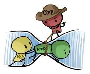
A circuit is a path for electricity to flow. Electric flow is the movement of electrons which always go from the positive pole to the negative pole (from the most loaded side to the less loaded side). There are two different types of circuits : parallel or series. Objects that are put in two circuits in parallel share the same voltage but the current is split. Objects that are put in series in a circuit split the voltage but share the same current.
Voltage (V in volts) is the electric pressiure or force between two points. It is the difference in the amount of charge. It is important not to give too much voltage to objects that require less to avoid damaging them. For a reference, a USB cable is 5 Volts, a car battery is 12 Volts and the electric plugs on the wall are 230 Volts.
Current (I in amperes) is the flow of the electrons.
Resistance (R in ohms) is the amount of material that resist the flow of electrons. Electrons flow from the external electron layer of an atom to the other. This is how the electron move, but if the atoms have electrons tighly attached, the resistance is going to be higher.
Ohm's Law relates these three parameters with the equation V = I x R.
Knowing the Ohm's law, we can understand the concept of a resistance which is an object that can be added to a circuit. If you add a resistance, it is the same as adding a tap and reducing the voltage of the electical circuit. The position of the resistance is not important in the circuit. The value of the resistance is coded on it with a color code.
There are two types of curents: AC which is alternate current and DC which is direct current. DC is the one that goes from the + to the - pole and the alternate that swiches the + and - poles x times per second. In europe, the frequence of the AC is 50 Hz.
Electrons are lazy, so the current is always going to go through the path with the less resistance. This is why all branches of a parallel circuit have to have the same resistance.
For more theoric information on electronics and for deeper understanding, Josep and Victor explained us concepts with the MDEF documentation.
Assignement
- Build at least one digital and one analogue soft sensors, using different materials and techniques.
- Document the sensor project as well as the readings got using the AnalogRead of Arduino
- Integrate the two soft sensors into one or two textile swatches using hard soft connections
- Document the circuit and it’s schematic
- Document your swatches
- Upload a small video of the swatches functioning
- EXTRA POINT Integrate the swatch into a project
Inspiration
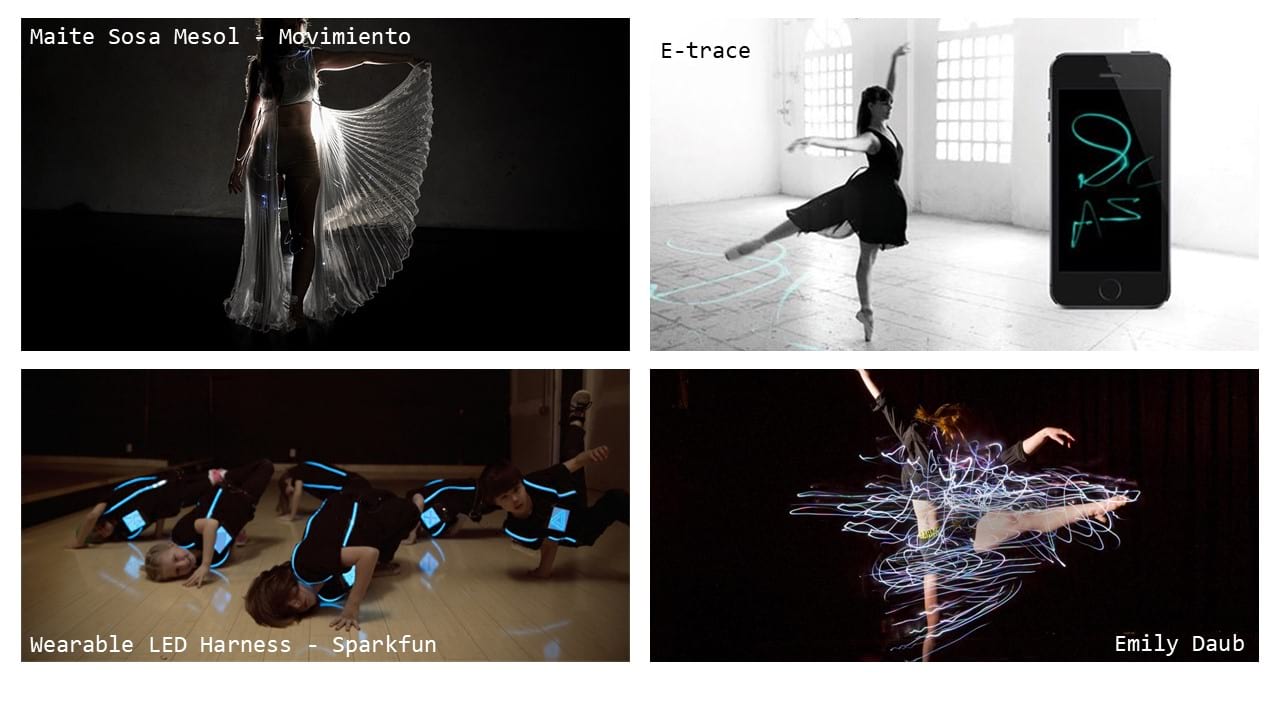
During the lecture, I was inspired by the wearable technologies used for artistic performances, especially the ones implying dance shows. I thus found amazing the sensors that could be integrated in garments and change the LED colors depending on the movements of the dancer.
I-Electronics on garments
Electronics can be integretad to garments thanks to the proprieties of the materials. Some fabrics have conductive proprieties. We can play with that to create a wearable circuit, but we can also play with conductive threads, conductive tape and conductive inks. A trace is a phsical path of conductive material on which electricity can circulate along, creating a circuit.
A list of the different types of conductive materials, threads and traces is available on Kobakant.
One has to be careful of the resistance of the material because if the circuit is long and the material is resistant, a lot of energy might be consumed.
To make the connection between electric components and the fibers, snaps or multi stranded wires can be used. The connections between the different components can also be permanent (sewing the LED in the garment or even solder it to the material). It is important to always cover the soldered joints with hot glue or material.
When designing circuits, we do not want them to overlap so we can use material, embroidery, beads, etc, to prevent short circuit.
For more information on e-textiles, this website offers a lot of information and the possibility to exchange with others.
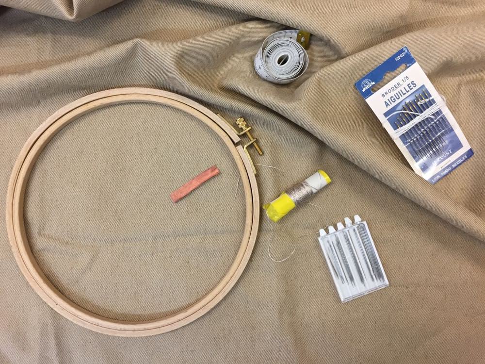
In Fabricademy barcelona, we had the regular sewing artillery (threads, needles, beads, pressure buttons, material) but also copper fabric and [Silverspun conductive yarn] (https://lessemf.com/fabric.html#237) to experiment.
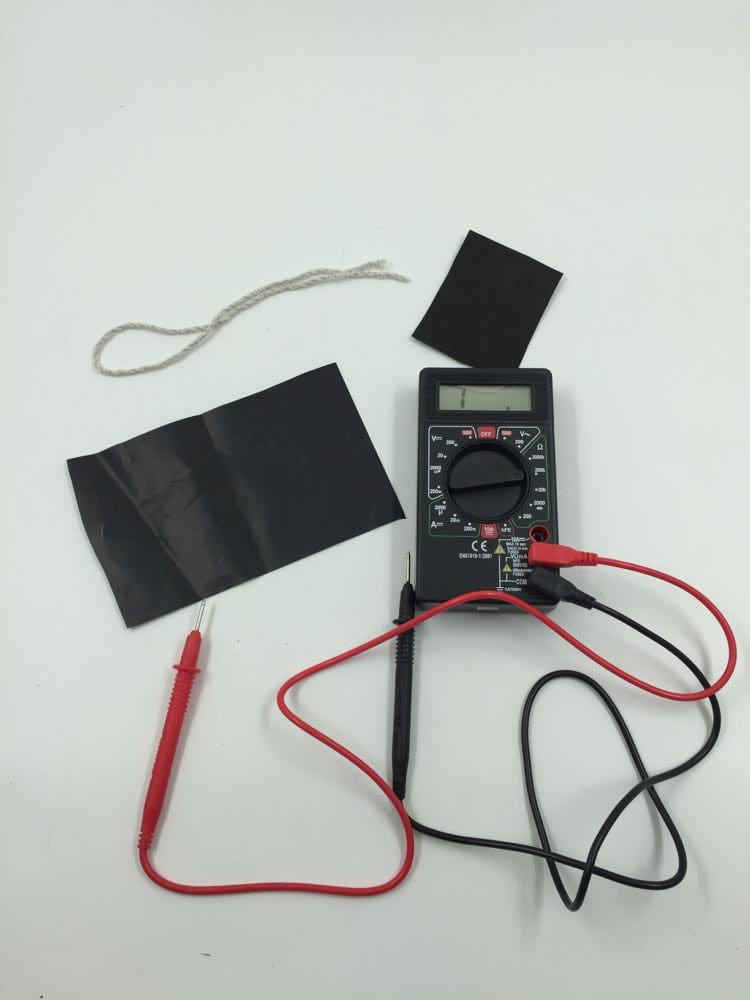
 The multimeter was also an indispensable tool to this week ! Here is a very clear video explaining how to use it properly.
II-Sensors
Sensors are electric components with wich we can interact. An interaction with a sensor causes a modification in the voltage of the circuit. There are two categories of sensors : digital or analog. Digital sensors generate discrete values (on or off) while analog generates a continum of values. An analog sensor is a variable resistance. Digital sensors are typically swiches. In order to swich analog into not digital data, we can play with the resistance of the circuit, providing more or less current. Resistance can be modified by playing with the distance of the wires and the lenght of the circuit, the surface of area or the surface of contact. An analog sensor works as a variable resistor, which means the resistance is not fixed and depends on other parameters. In order to test an analog sensor, we need a voltage divider.
In Fabricademy barcelona, we had velostat (piezoresistive sensor), eoontex (piezoresistive and thermic sensor) and conductive extensible thread (strech sensor) to create our own soft sensors. Piezoresistive materials have a variable electrical resistivity depending on the mechanical strain applied on them. This is due to their intrinseque constitution: pressiure changes their inter-atomic spacing, altering the circulation of electrons within the material.
III-Microcontrolers
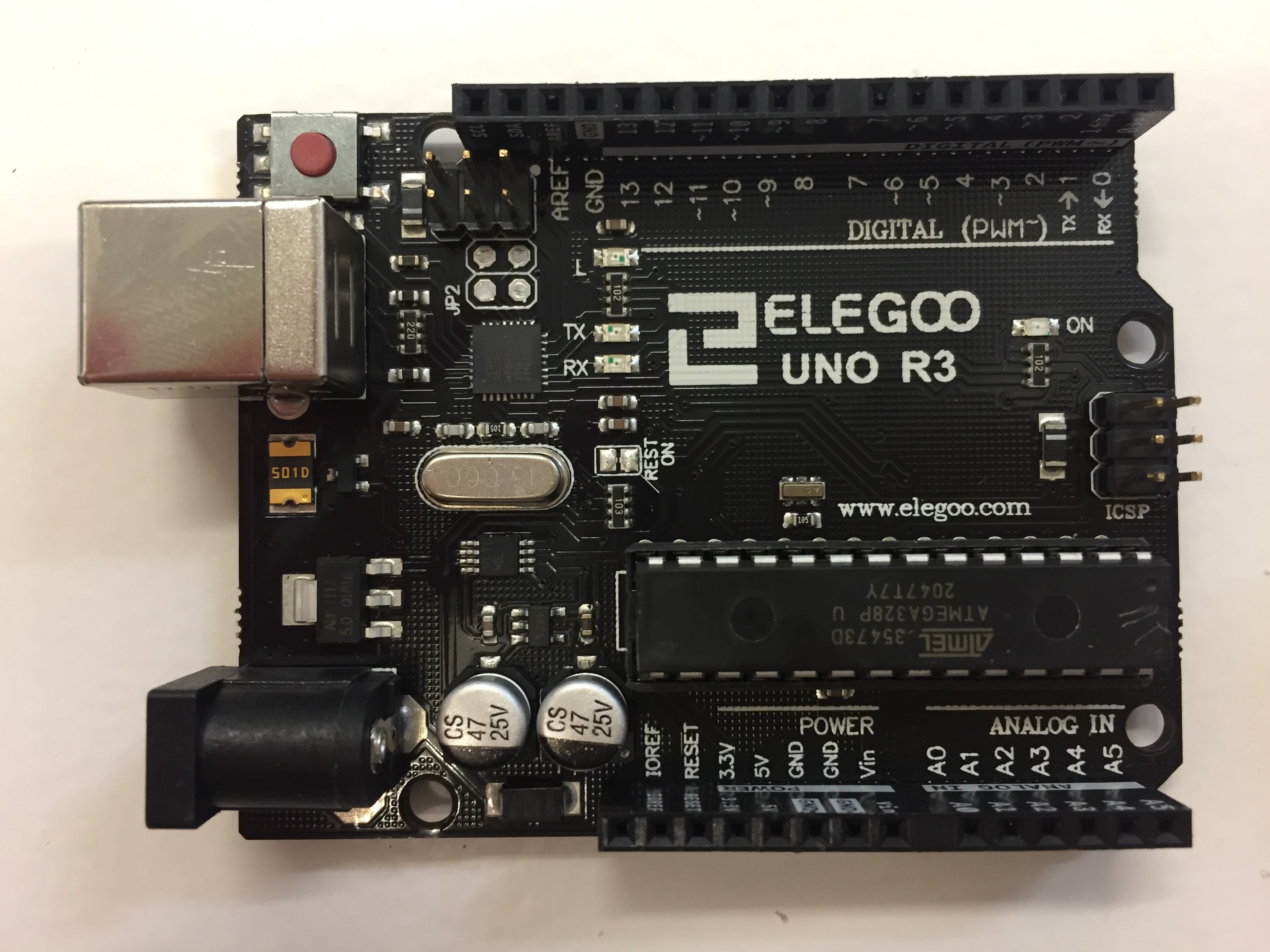
Programs can be encoded and integrated to garments. Arduino is an open source electronics prototping platform grouping hardware and software and offers different boards adaptable to wearables (LilyPad). It is important to start off with Arduino Uno. You have to program your Arduino through the IDE. It uses its own language which is a subpart of C++.
Analog pins are on the short line and the digital pins are one the long line. Pin 13 is already set to blink, and it is connected to the blinking LED. It is not possible to read a code encoded in an Arduino chip (you can only upload it from the computer to the chip but not the other way round).
Here are some important commands needed to program something on Arduino:
// is like # in python, it allows to write text that will not be executed when running the code, allowing to put comments next to the code.

Before starting a function, we can initialize variables.
int VariableName=value;       variable is a whole number
float VariableName=value;     variable is a decimal number
bool variable;                variable is a boolean

Void means "function". There are two types of functions:
void setup() {code}        action to make only once when the reset or power button are pressed
void loop() {code}         action to repeat indefinetly

||                         OR
&&                         AND

Inside the void setup() {}, we can decide to write some actions to execute.
setup(){
  pinMode (pinNumber, OUTPUT)
}

digitalWrite(pin, value);  gives a certain status of power to the pin of our choice (on or off)
analogWrite(pin, value);   gives a certain amount of power to the pin of our choice (0 to 255). Only works with the ~PWM pins.
delay(time)                waits the predicted time before doing the next command
if (condition)             exectute the action depending on the condition
  action
else                       dictates the action to do when the "if" condition is not respected
  action

Inside the void setup() {}, we can also decide to read the information from a source.
setup(){
  pinMode (pinNumber, INPUT)
}
digitalRead(pinNumber)     reads the values recieved on pin 9, only off and on
lecture = digitalRead(9)   gives the variable "lecture" the value of pin 9
analogRead(pinNumber)      reads the values recieved on pin 9, from 0 to 255
Here is an example of an easy code turning on and off a LED every second.
void setup() {
  pinMode(13, OUTPUT);               // initialize digital pin 13 as an output.
}

void loop() {
  digitalWrite(13, HIGH);            // turn the LED on (HIGH is the voltage level)
  delay(1000);                       // wait for a second or 1000 milliseconds
  digitalWrite(13, LOW);    // turn the LED off by making the voltage LOW
  delay(1000);                       // wait for a second
}
Here are some parameters to set on Arduino software to be able to push it to the hardware and that can be useful to create new programs:
IV-Creating a digital soft sensor
I did not have much inspiration for the digital sensor, but I appreciated learning about the coding. So for the moment, I do not have a final soft digital sensor. But I experimented with Arduino software and hardware. This is a footage of a swich button I made using Arduino.
After this, one of our instructors gave us a challenge to find a code to make a toggle swich instead of a momentary swich. I did not succeed but there is a lot of documentation on the internet and I am obviously not the first person who wanted to do that. Here is the code I made (that did not work) and under it is the code that works I found on the arduino website.
What I did:
int lecture;
int Button = 8;
int LED = 1;
bool Status;

void setup () {
  pinMode (Button,INPUT);
  pinMode (LED, OUTPUT);
  Serial.begin(9600); // indicates we are sending information from arduino to the screen. Defines the baud rate (number of bits sent per second, the speed and amount of info we want to send)
}
void loop () {
  lecture = digitalRead(Button);

  if (lecture == LOW && Status==false){
    Status=true;
  }
  if (lecture == LOW && Status == true){
    Status=false;
  }

  if (Status==false){
     digitalWrite(LED,LOW);
  }
  else {
     digitalWrite(LED, HIGH);
  }

  Serial.println(lecture); //prints on the serial monitor screen the values at the speed of 9600 bites per second. The values will be printed in different lines in the serial monitor or plotted in the serial plot.
  delay (200);
}
What I should have done:
int LED = 1;
int Swich = 8;
int lecture;
bool StatusSwichOld;
bool StatusSwichNew;
bool StatusLED;

void setup() {
  StatusSwichOld = false;
  StatusSwichNew = false;
  StatusLED = false;
  pinMode(LED, OUTPUT);
  pinMode (Swich, INPUT);
  Serial.begin(9600);
  digitalWrite (LED, LOW);
  }

void loop() {
  lecture = digitalRead(Swich);
  StatusSwichNew=digitalRead(Swich);
  if (StatusSwichOld != StatusSwichNew){
    if (StatusSwichNew == true){
      if (StatusLED == false){
        digitalWrite(LED, HIGH);
        StatusLED = true;
      }
      else{
        digitalWrite (LED, LOW);
        StatusLED = false;
      }
    }
    StatusSwichOld=StatusSwichNew;
  }
  Serial.println(lecture);
}
Not exactly the same logic !
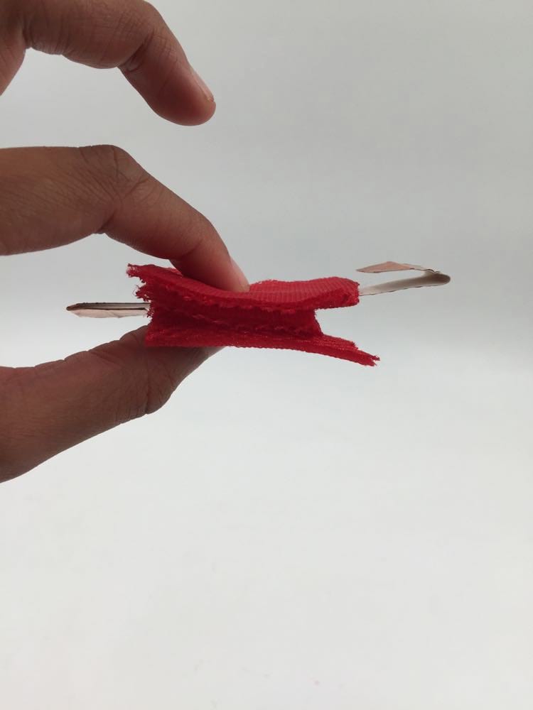
Update: some weeks later, I made a very basic analog sensor using some foamy material, some adhesive copper and some white glue. Sandwich them all together and tadaaam: here you have a digital sensor!
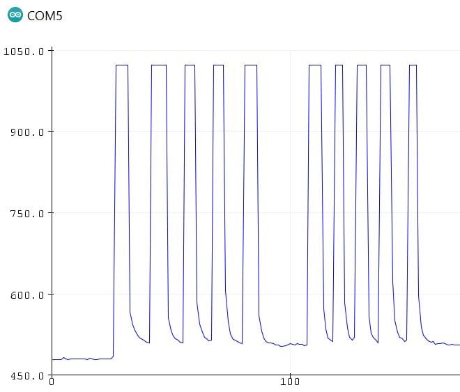
After testing it on Arduino, I obtained this plot proving the swich works !
Here is a video of the digital sensor working in the format of a swatch. The battery is a 3.7V rechargable battery, hidden in a pocket. I used conductive embroidery thread for the traces. The blue LED lights up when the circuit is closed. I did not add any resistor since the thread is already a resistive and the battery does not have that much voltage.
V-Creating an analog soft sensor
a-Idea
For this week's assignement, we had to create an analog soft sensor. My idea was to make a sensor that would be integrated in a garment for dancers. The sensor I wanted to make was a strech sensor to be placed on the top of the back of the dancer and which's resistance would vary depending on the arms and back movements. This sensor would be connected to RGB LEDs located on the shoulders and emitt a different shade of light, rangig from red/pink/violet/blue.
b-Preliminary fails
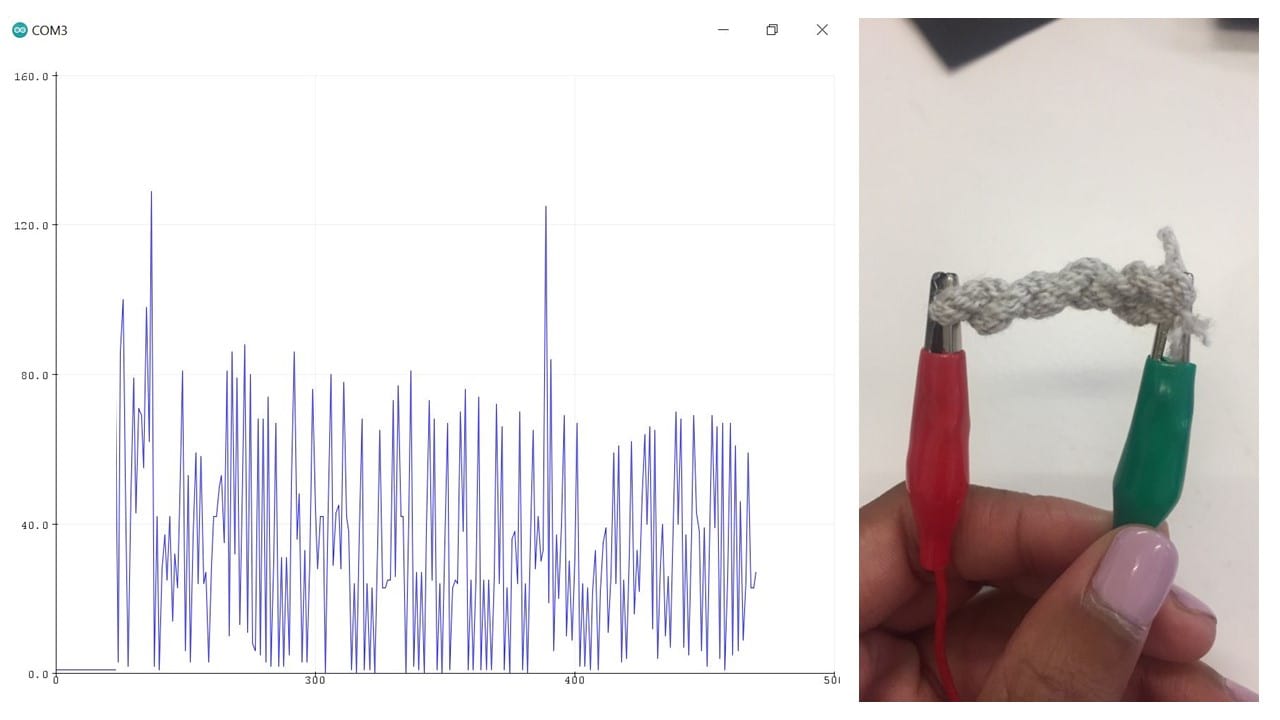
I first wanted to make a strech sensor (see code in the last paragraph of this page) using conductive thread, but once I integrated the thread in the circuit, the fluctuations of the values were really random, not related to the streching stimulation and only covered a very small range of values. Then I tried to twist the thread to have a better result since the diameter and the contact surface was wider, but the results were the same.
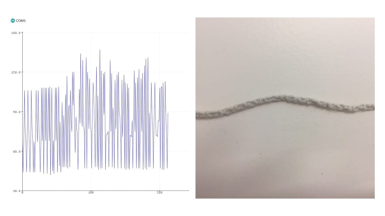
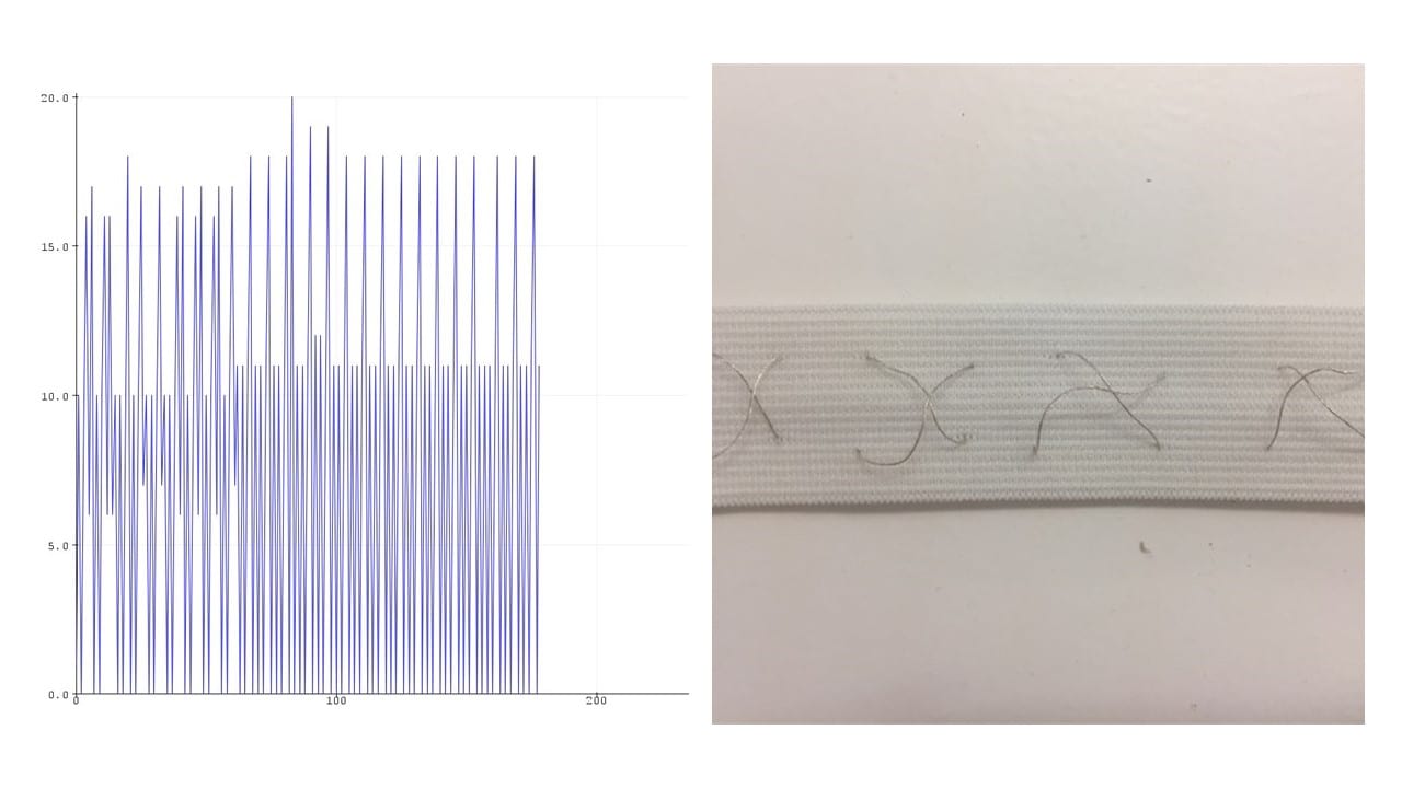
I then tried to make another strech sensor, a DIY one as explained on kobakant's page dedicated to strech sensors, but the values I got were not consistent either.
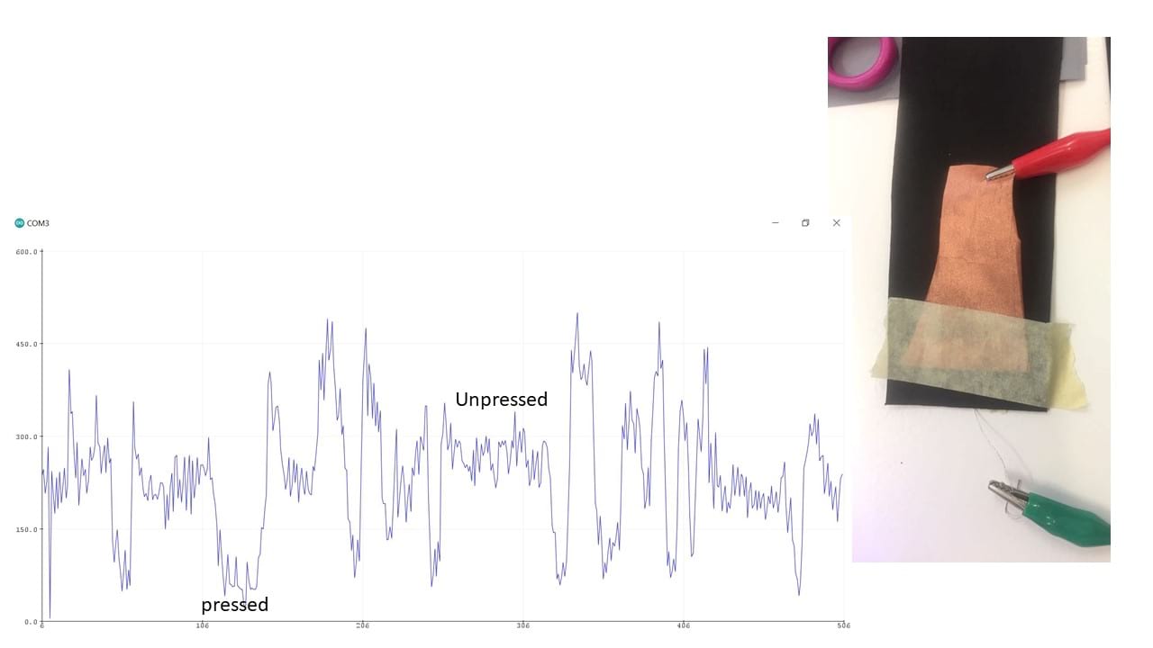
In the end, I was pretty stuck... That is why I decided to abandon the idea of making a strech sensor but kept the initial idea. I decided that the movement of the dancer would be translated in lights of different colours depending on the temperature of the person and on the pressure applied between the cloth and their skin, using the eoontex fabric. When measuring the values obtained, I had a non-perfect-yet-more-exploitable plot, so I settled for that.
c-Soft sensor construction
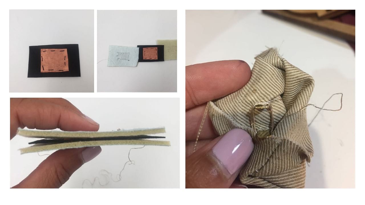
To build the sensor, I sandwiched a lot of different fabrics together. First, I put a layer of copper on each side of the eoontex fabric. Then I connected the copper to a thread by embroidering conductive thread on a foamy material and sandwiching them together. Then, I isolated everything from the body by covering and packing it into fabric. The conductive threads were connected to the exterior with pressure buttons and the whole sensor was closed by sewing.
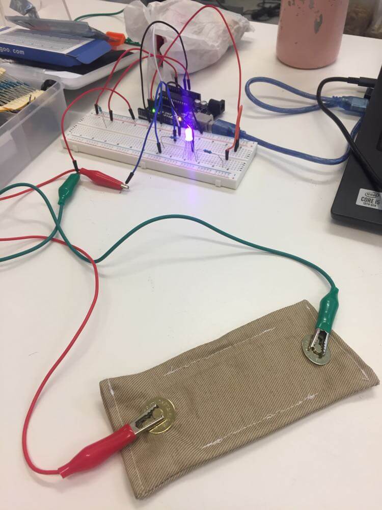
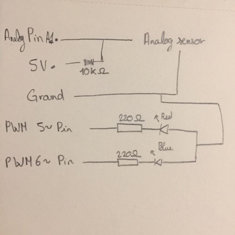
d-Arduino code
In the end, this is the code I made to translate the signal recieved from the sensor into different colours in the LED. In order to make this code function, I first made this circuit and then uplodaded the following code into Arduino.
int lecture ;
int AnalogPin = A1 ;
int LED1 = 5;
int LED2 = 6;
int mapping;

void setup (){
  pinMode(AnalogPin, INPUT);
  pinMode(LED1, OUTPUT);
  pinMode(LED2, OUTPUT);
  Serial.begin (9600);
}

void loop (){
  lecture = analogRead (AnalogPin);
  mapping = map(lecture,0,80,0,255);
  analogWrite(LED1, mapping);
  analogWrite(LED2, -mapping);
  Serial.println (lecture);
  delay(100);
}
And here is the final color gradient obtained depending on the pressure applied on the sensor !
Here is a video of the digital sensor working in the format of a swatch, giving a different intensity of lighting to the LED depending on the pressure.