05 | E-TEXTILES
WEEK 05 | E-TEXTILES This week was about understanding electronic circuits, sensors and getting to know more about Arduino
INSPIRATION
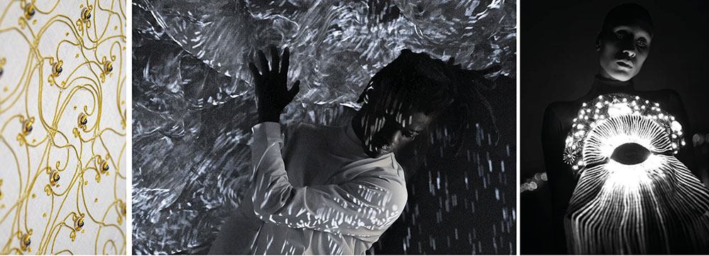 The embroidered computer by Irene Posch and Ebru Kurbak | Adrien M & Claire B | Clara Daguin
I discovered the work of Irene Posch and Ebru Kurbak and their piece The embroidered computer which is wonderful. I was really happy to see some gold work embroideries and it opened to ideas of materials that I already knew but wouldn't have thought about for this class. In embroidery, gold work uses specific metal threads as cannetille (translation ?). In France there is only one formation where you can learn gold work design and it is based in Bretagne (Rochefort). E-textiles also reminded me of Adrien M and Claire B's beautiful work with dance and light. Also, the work of Clara Daguin, an embroiderer who uses electroluminescent wires.
WHAT YOU NEED TO KNOW
Components
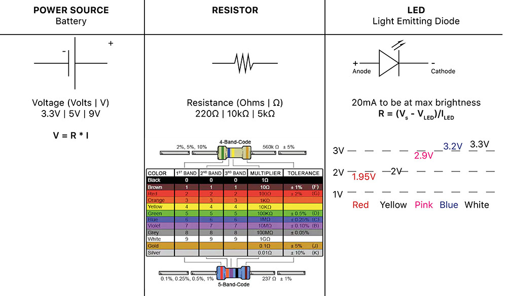 picture from the color chart for Resistor
Useful links
Inputs
- Digital [ON/OFF] : the LED will switch on and off | Tilt switch, Momentary switch, ON/OFF switch
- Analog [Value 1, Value 2...] : the LED will be more or less bright
How to change resistance
- Resistance increases over distance
- When pressure is applied to some materials it will decrease the resistance.
- Increasing the size of the area for the electricity to flow will decrease the resistance
MAKING SENSORS WITH CROCHET | Soft Sensors
This week I really wanted to do crochet and thought it could be a good way to make soft sensors. I like to make crochet because it is an easy and quick technique that can be repaired quite easily too.
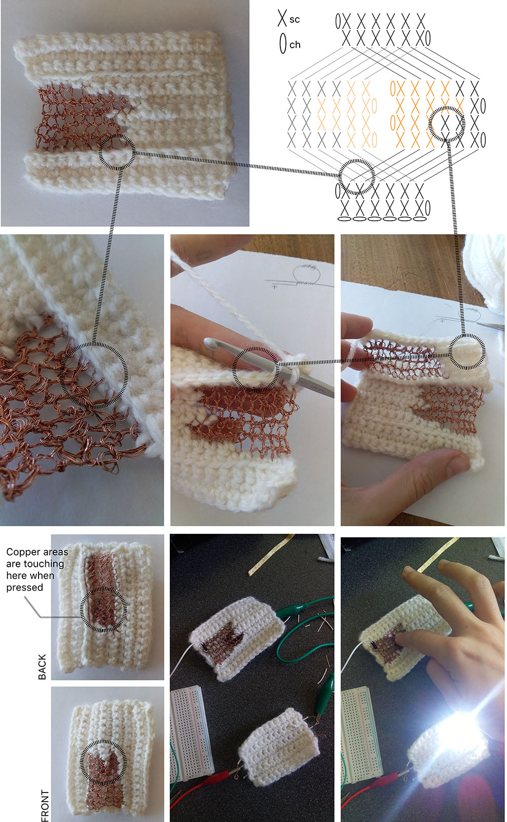
Digital sensor
First, if you're not used to crochet technique, please go check those pages and Youtube tutorials :) Crochet is quite easy to get along with by yourself and once you understand how it works you can work in 2D or 3D !
Chart symbols here How to read diagrams here
For this digital sensor I wanted to get rid of the non conductive foam part and I thought that crochet could help me with creating a 'tube structure' which would become conductive when pressed. I worked only with single stitches which are the basic ones. I used a second-hand sourced synthetic white thread and copper wires (also second hand sourced). I used a 4.0 crochet for this sample but of course you can change depending on your thread ! Also good to know that I usually crochet very tight (so if you want something less tight you can use a bigger crochet for the same thread). In the following picture you can see the differents steps. The diagram is simplified for better understanding : it doesn't have the same amount of rows and stitches than the sample. If you get the idea you'll be able to reproduce it at the desired size.
Due to the two metallic parts being crocheted whether on the back or on the front, when pressure is released, the copper wires are not touching ! This works well because the other yarn used is quite thick in regards to the copper wire that is used. If the sample is stretched, it will probably touch though.
Integrating LEDs in
Video soon
Analog sensor
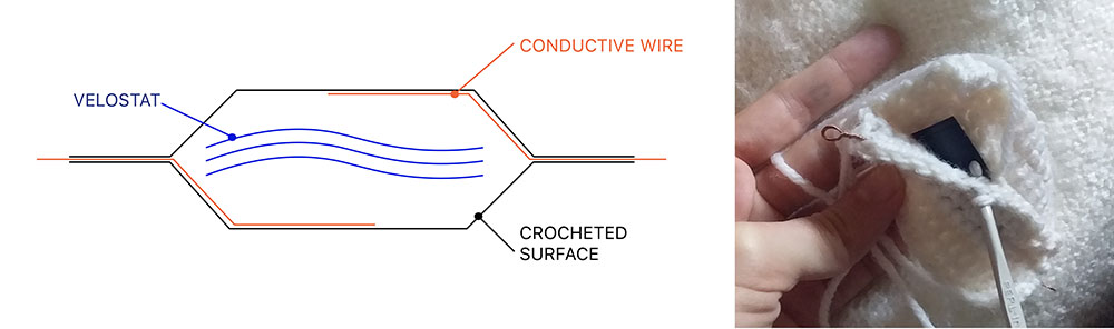
The idea was to integrate velostat in a crocheted pocket. The connecting parts can be crocheted with copper wire or added inside the pocket so that there are invisible :) I did one sample with 3 layers of velostat inside the pocket. As you can see the LED is bright even when the sensor isn't working. I think it might be because of the 3 layers (and not 2 as we made for the first sample) : they probably are too conductive.
Links to explore further crochet x sensors :
USING A DIGITAL EMBROIDERY MACHINE TO MAKE A SOFT CIRCUIT
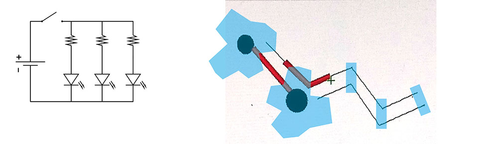
Parallel circuit with 3D LEDs
Goals
- Integrate 3 LEDs in the circuit
- Make a digital sensor out of conductive thread for embroidery and conductive wire mesh
- Make a pocket for the battery
We wanted to put 3 LEDs in our circuit so we had to make a parallel circuit. As you can see on the picture below, we translated the circuit scheme for the embroidery. The blue parts (clouds and LEDs) were added after the embroidery by hand.
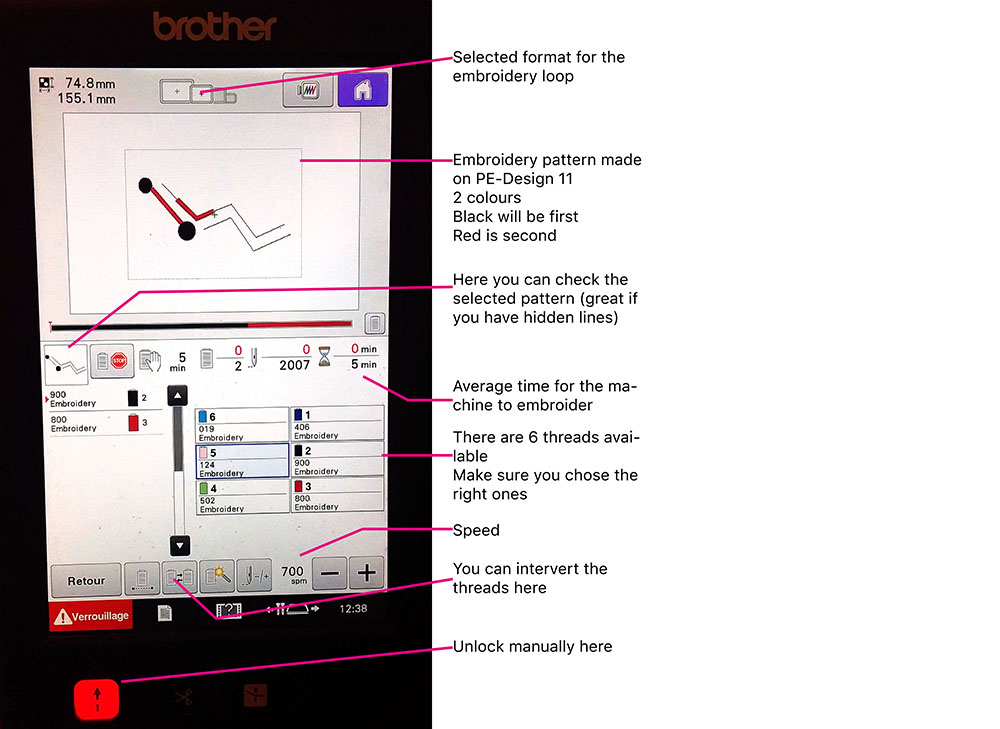
How to use a Digital Embroidery machine
We are working with the PE-Design 11 software and a PR670E Embroidery Machine. To start, open the software and follow the steps :
- chose the size of the embroidery loop : Design Settings > 100 x 120 mm
- draw your pattern using Shapes/Lines | Download your pattern (WMF format) : import > from vector image
- chose the colours wisely and check the order for the different embroideries (like if one is crossing another, which one do you want to be on top ?)
- if you don't want the embroidery machine to cut the thread at the end of the embroidery, use the small scissors icon
Once you're pattern is ready on PE-Design 11 you can save it on a USB key and upload the file on your embroidery machine.
GETTING TO KNOW ARDUINO
Tool>Board>Arduino Uno | Tool>Port>/dev/cu.usbmodem14101(Arduino Uno)
BLINK function
int led=13
void set up() {
    pin Mode(led, OUTPUT)
}

void loop () {
    digitalWrite(led, HIGH);
    delay(1000);
    digitalWrite(led,LOW);
    delay(1000);
}
Digital Sensor
BUTTON function Digital Read
const in buttonPin = 2;
const int ledPin = 13;

int buttonState = 0

void set up() {
    pinMode(ledPin, OUTPUT);
    pinMode(buttonPin,INPUT);
}

void loop() {
    buttonState = digitalRead(buttonPin);
    if (buttonState == HIGH) {
        digitalWrite(ledPin, HIGH);
    }
    else {
        digitalWrite(ledPin, LOW);
    }
}
In the following video there are examples of programming you can do with Arduino. The codes are below the video.
BUTTON x BLINK FAST or SLOW
const in buttonPin = 2;
const int ledPin = 13;

int buttonState = 0

void set up() {
    pinMode(ledPin, OUTPUT);
    pinMode(buttonPin,INPUT);
}

void loop() {
    buttonState = digitalRead(buttonPin);
    if (buttonState == HIGH){               //when button is pressed, the LED blinks very fast
         digitalWrite(led, HIGH);
         delay(100);
         digitalWrite(led,LOW);
         delay(100);
    }
    else {                                  // when button is released, the LED blinks slowly
         digitalWrite(led, HIGH);
         delay(5000);
         digitalWrite(led,LOW);
         delay(5000);
    }
}
you can do the same with adding the function fade into the void loop function :
BUTTON x BLINK x FADE
const in buttonPin = 2;
const int ledPin = 3;
int brightness = 0;
int fadeAmount = 5

int buttonState = 0

void set up() {
    pinMode(ledPin, OUTPUT);
    pinMode(buttonPin,INPUT);
}

void loop() {
    buttonState = digitalRead(buttonPin);
    if (buttonState == HIGH){               //when button is pressed, the LED fades
        analogWrite(ledPin, brightness);
        brightness = brightness + fadeAmount;
        if (brightness <= 0 | | brightness >= 255) {
            fadeAmount = -fadeAmount;
        }
        delay(30);
    }
    else {                                // when button is released, the LED blinks slowly
         digitalWrite(led, HIGH);
         delay(100);
         digitalWrite(led,LOW);
         delay(100);
    }
}
For the two previous programs you can use this montage :
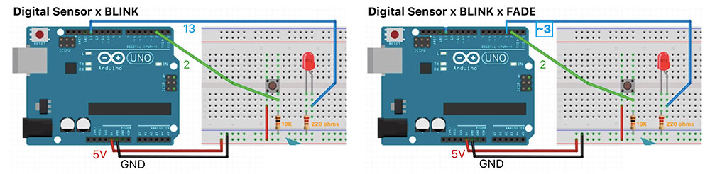
Without Resistor
pinMode(buttonPin,INPUT_PULLUP);
Reading Sensor Values
int sensorPin = A0;
int ledPin = 9;
int sensorValue = 0;

void setup() {
    pinMode(ledPin, OUTPUT);
    pinMode(sensorPin, INPUT);
    Serial.begin(9600);
}

void loop() {
    sensorValue = analogRead(sensorPin);
    analogWrite(ledPin);
    Serial.println(sensorValue);
}
REFERENCES
- The embroidered computer, by Irene Posch
- E-embroideries by Clara Daguin
- Adrien M & Claire B
- Color Chart for Resistor
- LED resistor Calculator
- Knit Stoke Sensors by Pauline Vierne and Hillary Grant
- KOBAKANT
| Videos | Class, Review 05, Tutorial Basic Electronics, Tutorial Intro to Arduino |
|---|---|
| Softwares | Arduino, PE-Design 11 |
| Tools | Arduino Uno, PR670E Digital Embroidery Machine |