08 | WEARABLES
WEEK 08 | WEARABLES This week was about getting to know more about Actuators (output devices).
INSPIRATION
Thermochromic Inks, Sound and Movement
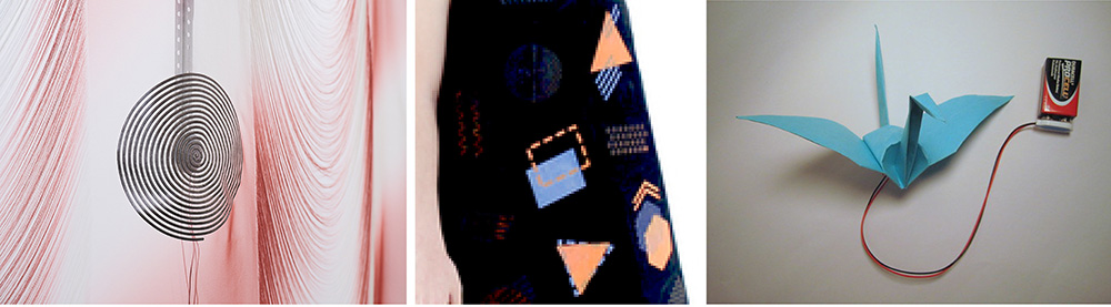 Draping Sound, 2019 Sound installation/ Performance with textiles augmented into a multichannel electroacoustic transducer by EJTECH, photography by Miro Kuzmanovic | My heart on my dress, 2016, by Jingwen Zhu | Electronic Origami Flapping Crane, high-low tech
Wearing electronics
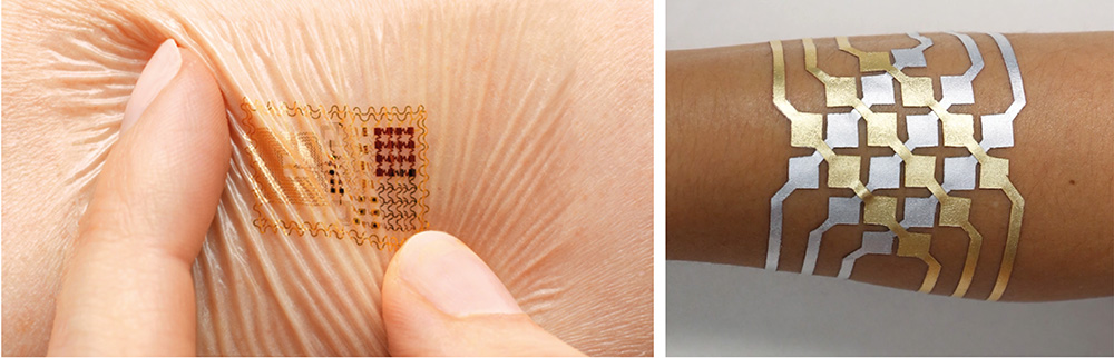 Biostamp temporary tattoo by John Rogers from MC10 (healthcare and cosmetics applications) | DuoSkin, C. Hsin-Liu Kao, A. Roseway, C. Holz, P. Johns, A. Calvo, C. Schmandt from MIT Lab
I completly love the DuoSkin project from MIT Lab ! Quite impressive to see how you can be connected to a computer interface only with a thin layer of metal on your skin. It also seems easy to make (which I don't think is the case in reality). I'd love to try it out for the skin electronics week :)
Biostamp temporary tattoo by John Rogers from MC10 (healthcare and cosmetics applications) | DuoSkin, C. Hsin-Liu Kao, A. Roseway, C. Holz, P. Johns, A. Calvo, C. Schmandt from MIT Lab
I completly love the DuoSkin project from MIT Lab ! Quite impressive to see how you can be connected to a computer interface only with a thin layer of metal on your skin. It also seems easy to make (which I don't think is the case in reality). I'd love to try it out for the skin electronics week :)
Playing around with actuators
Led On/Off
Sketch from Emma Pareshi to switch on/off a LED each time the pushbutton (digital sensor) is pressed.
/*
Emma Pareschi 2020
*/

int  sw_pin = 2;    // the pin that the pushbutton is attached to
int counter_reset = 2; //variable to reset the counter
int led_pin = 3; //pin of the led

int counter = 0;   // counter for the number of button presses
int sw_status = 0;         // current state of the button
int last_sw_status = 1;     // previous state of the button

void setup() {
  pinMode(sw_pin, INPUT_PULLUP);
  pinMode(led_pin, OUTPUT);
  Serial.begin(9600);  // initialize serial communication
}

void loop() {
  sw_status = digitalRead(sw_pin);
  if (sw_status != last_sw_status) {
    if(sw_status == HIGH){     //if the status is HIGH, the switch was relaised
      counter = counter + 1;   //increase the counter of 1 unit
    }
    delay(50);
  }

  Serial.print("Counter: ");  //print on Serial monitor the counter value
  Serial.println(counter);

  last_sw_status = sw_status;   //set the last status
  if (counter == counter_reset){
    counter = 0;
    }

  if (counter == 0){             //if the counter is ZERO
    digitalWrite(led_pin, LOW);  //Led if off
  } else {                        //otherwise (if it is 1)
    digitalWrite(led_pin, HIGH);
   }
}
Electromagnet
When you put current inside a conductive wire ring, it creates a magnetic field with "South" and "North" poles. Reversing the current will change the South/North ways. If a magnet is placed in the ring it will jump as soon as a current (in the right way) will be applied.
CONNECTING A BATTERY TO ARDUINO and OUTPUT DEVICES
Because we were gonna use some output devices which consume more current than the Arduino pin can provide, we had to make a circuit driver with a Mosfet transistor and a flyback Diode.
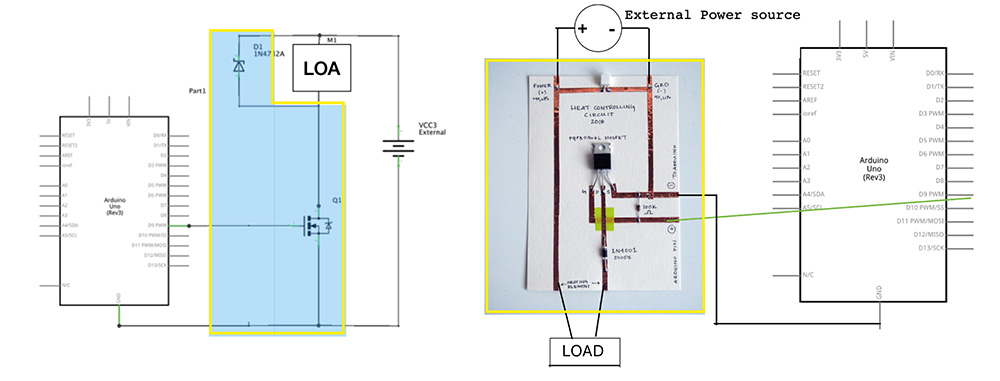 Pictures from the course
You can find the fabrication steps on the website of Alumni Jessica Stanley
SMA | Shape Memory Alloy
Useful Links
- Patty Jansen Alumni's website
- Sara Alvarez Alumni's website
- SMA Smocking Swatch Example on Kobakant
- Shape Memory Alloy Training on Kobakant
- Flexinol experiment by Liza Stark
- Electronic Origami Flapping Crane by high-low tech
How it works
To work with Shape Memory and electricity you can use a shape memory alloy called flexinol. It is an actuator wire which contracts (10%) when heated above its transition temperature !
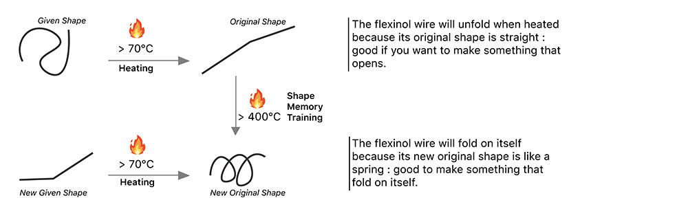
It took us some time to understand how it works but we finally figured it out. This wire is like a heating element so you have to use a circuit driver with it to provide more power. Depending on your project you need to decide of what will be the original shape, be sure the wire remembers it by heating it at 400°C in this wanted shape. Then, you can check if it's good by putting it straight into a hot glass of water. It should go back to its original shape.
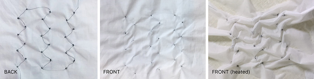
Canadian Smock
We wanted to experiment with Canadian smock for this actuator. In order to do so, we took a wave pattern and decided to replace the knots with flexinol. When heated to fabric would fold in the smock shape. We trained our wire in a spring shape so that it would contract on itself when heated. You can see below an example on the first fold of the smock (battery 9V).
We connected the sample to Arduino following the schema below :
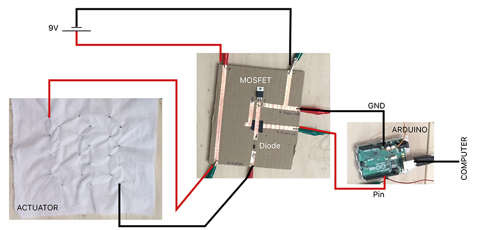
So it was going great so far ! But what we forgot is that the more you add flexinol elements the more you're gonna need power... Our smock is ready to be tested but actually we don't have enough power to make it heat enough :( You can see below the folds that we're supposed to have when there is enough power (we used hot water to make the flexinol contract).
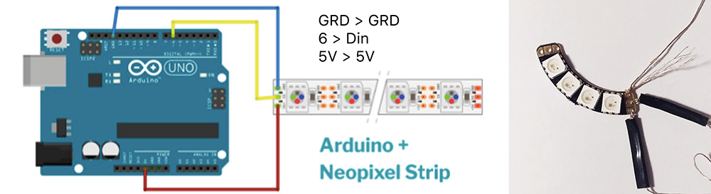
NEOPIXEL STRIPS
Working with Neopixel strip (RGB strips) and Arduino following this schema from the tutorial:
First I had to add the Adafruit Neopixel Library : Arduino > Sketch > Include Library > Manage Libraries > Adafruit Neopixel > Download > Close
Then you should find the examples here : File > Examples > Adafruit NeoPixel
Some tests with sketches by Emma :)
Rainbow + Digital switch
#include <Adafruit_NeoPixel.h>
#define LED_PIN    6
#define LED_COUNT 4
Adafruit_NeoPixel strip(LED_COUNT, LED_PIN, NEO_GRB + NEO_KHZ800);

uint32_t off = strip.Color(0, 0, 0);
int num_rainbow = 1;
int sw_pin = 2;           //digital switch pin
int sw_status = 0;         // current state of the button

void setup() {
  strip.begin();           // INITIALIZE NeoPixel strip object (REQUIRED)
  strip.show();            // Turn OFF all pixels ASAP
  strip.setBrightness(50); // Set BRIGHTNESS to about 1/5 (max = 255)
  pinMode(sw_pin, INPUT_PULLUP);
  // Serial.begin(9600);
}

void loop() {
   sw_status = digitalRead(sw_pin);

   if (sw_status == 0){
      rainbow(10);             // Flowing rainbow cycle along the whole strip
      strip.fill(off, 0, 10);
      strip.show();  //display the color
    }
}

// Rainbow cycle along whole strip. Pass delay time (in ms) between frames.
void rainbow(int wait) {
  for(long firstPixelHue = 0; firstPixelHue < num_rainbow*65536; firstPixelHue += 256) {
    for(int i=0; i<strip.numPixels(); i++) {
      int pixelHue = firstPixelHue + (i * 65536L / strip.numPixels());
      strip.setPixelColor(i, strip.gamma32(strip.ColorHSV(pixelHue)));
    }
    strip.show(); // Update strip with new contents
    delay(wait);  // Pause for a moment
  }
}
Wipe + Digital switch
#include <Adafruit_NeoPixel.h>

#define LED_PIN    6
#define LED_COUNT 4
Adafruit_NeoPixel strip(LED_COUNT, LED_PIN, NEO_GRB + NEO_KHZ800);

uint32_t off = strip.Color(0, 0, 0);
int sw_pin = 2;
int sw_status = 0;

void setup() {

  strip.begin();           // INITIALIZE NeoPixel strip object (REQUIRED)
  strip.show();            // Turn OFF all pixels ASAP
  strip.setBrightness(50); // Set BRIGHTNESS to about 1/5 (max = 255)

  pinMode(sw_pin, INPUT_PULLUP);
  Serial.begin(9600);

}

void loop() {

   sw_status = digitalRead(sw_pin);

   if (sw_status == 0){
      colorWipe(strip.Color(255,   0,   0), 50); // Red
      strip.fill(off, 0, 10);
      strip.show();  //display the color
    }
}

// Fill strip pixels one after another with a color. Strip is NOT cleared
// first; anything there will be covered pixel by pixel. Pass in color
// (as a single 'packed' 32-bit value, which you can get by calling
// strip.Color(red, green, blue) as shown in the loop() function above),
// and a delay time (in milliseconds) between pixels.
void colorWipe(uint32_t color, int wait) {
  for(int i=0; i<strip.numPixels(); i++) { // For each pixel in strip...
    strip.setPixelColor(i, color);         //  Set pixel's color (in RAM)
    strip.show();                          //  Update strip to match
    delay(wait);                           //  Pause for a moment
  }
}
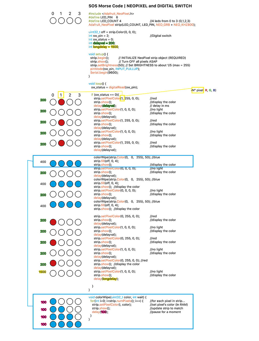
Turning Neopixel strip into a SOS Morse code distress signal (Digital Switch)
I thought I could try to make a morse code with the neopixel strip and a digital switch. You can see below what I wrote to obtain the Morse code SOS which is written like this : ▄ ▄ ▄ ▄▄▄ ▄▄▄ ▄▄▄ ▄ ▄ ▄ Download the sketch here
REFERENCES
- Preparing to use actuators mosfet circuit by Jessica Stanley
- Draping Sound, EJTECH, 2019
- Biostamp temporary tattoo electronic circuits by MC10, Rose Etherington, DEZEEN, 2013
- Wearable Healthcare Technology, John Rogers from MC10
- My heart on my dress by Jingwen Zhu
- DuoSkin, C. Hsin-Liu Kao, A. Roseway, C. Holz, P. Johns, A. Calvo, C. Schmandt from MIT Lab
- Patty Jansen Alumni's website
- Sara Alvarez Alumni's website
- SMA Smocking Swatch Example, Kobakant DIY
- Shape Memory Alloy Training, Kobakant DIY
- Flexinol, video by Liza Stark
- Electronic Origami Flapping Crane, high-low tech
| Videos | Class, Review 08, Tutorial Arduino and Power Loads, Tutorial Arduino, Neopixels and Sound** |
|---|---|
| Softwares | Arduino |
| Tools | Arduino Uno, Shape Memory Alloy, Thermochromic Inks |